Quantcast
Channel: Electro help
Viewing all 2033 articles
Browse latest View live

HOW TO DISASSEMBLE DELL E1909 19” LCD MONITOR

$
0
0
Dell E1909_19" lCD Monitor_Disassemble Procedure. [Horizontal Frequency: 30 kHz to 83 kHz]
Click on the pictures to Zoom In
DISASSEMBLY
* Put the monitor on the soft plane table, to avoid scrapping the panel.
* Remove the cable cover as the arrow shown.
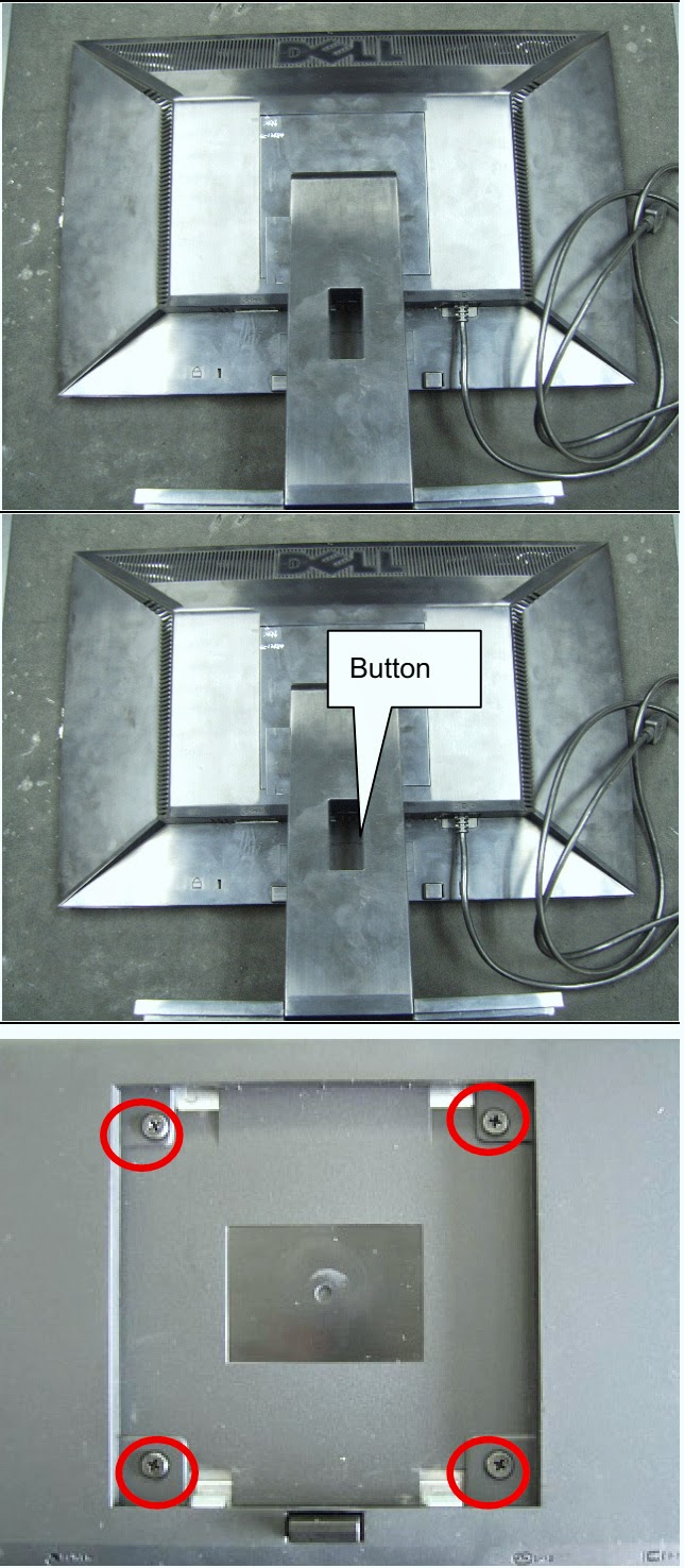
* To remove stand press the button at the same time pull out the hinge cover follow the arrowhead direction and remove it, then remove the hinge.
* Remove the four screws and remove the base.
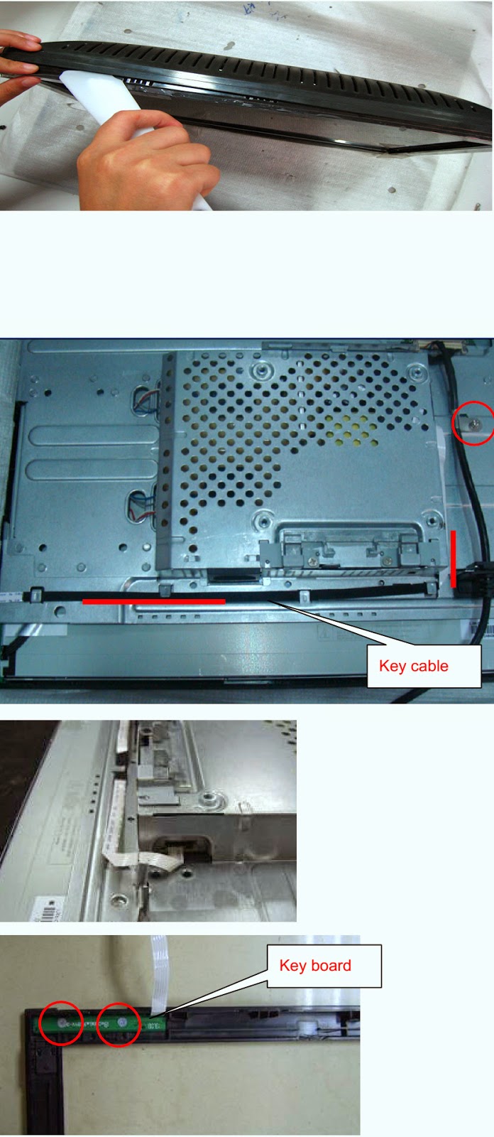
* Pry the monitor up then find out the hooks’ position, use the tool (like the picture or other card) to insert into the gap of bezel and rear cover, then turn over the monitor and take off the rear cover.
* Remove the key board: Remove the screws marked in red.
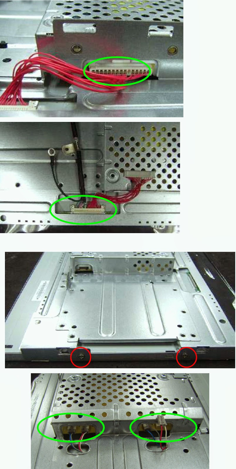
* Disconnect connector remarked in green.
* To remove shield: Remove the four screws and remove the main frame by manual or torque = 3kgF.Cm and disconnect connector marked in green.
*To remove the power board: Remove the screws remarked in red.


SONY PRS-T1- DIGITAL BOOK READER - DISASSEMBLE PROCEDURE

$
0
0
Sony PRS-T1- DIGITAL BOOK READER US Model; Canadian Model; AEP Model & UK Model _ Disassemble Procedure
Click on the pictures to Zoom In
 ABOUT THE LEAD WIRE OF BATTERY ASSY (BAT1)
Confirm the operation after pressing the button of the main unit bottom without fail when soldering the BATTERY ASSY (BAT1) to the MAIN board.
DISASSMEBLE - CASE REAR ASSY
MAIN BOARD
CASE FRONT ASSY
BATTERY ASSY (BAT1)

TEST MODE - FACTORY INITILIZE - SONY SONY DIGITAL BOOK READER- PRS-T1

$
0
0
FACTORY INITILIZE – TEST MODE – SONY DIGITAL BOOK READER- PRS-T1
TEST MODE
PREPARATION OF THE TEST MODE
Prepare the following before executing the test mode.
* PC
* USB cable for PC connection (MICRO B)
* File for the test mode
Note: Confirm the method of obtaining the file for test mode to each service headquarters.
Procedure:
* Press the [Power] key to turn the power on.
* Confirm the HOME menu was completely displayed, and connect this unit to PC by the USB cable (MICRO B).
* Confirm the USB connection screen displayed, and touch the “Data Transfer Mode”.
* Confirm the “READER” drive of this unit is recognized.
* Copy the file for the test mode from PC to directly under the “READER” drive of this unit.
* Remove this unit and USB cable (MICRO B) from PC.
* Confirm the HOME menu was completely displayed, and press the key as following order.
After a while, the test mode menu is displayed, and this unit enters the test mode.
RELEASING THE TEST MODE
* Press the [Return] key, and confirm the HOME menu was completely displayed.
* Connect this unit to PC by the USB cable (MICRO B).
* Confirm the USB connection screen displayed, and touch the “Data Transfer Mode”.
* Confirm the “READER” drive of this unit is recognized.
* Delete the file for the test mode from directly under the “READER” drive of this unit.
* Remove this unit and USB cable (MICRO B) from PC.
* Confirm the HOME menu was completely displayed, and press the key as following order, and confirm that the test mode does not enter.
* Press the [Power] key for 5 seconds or more, and touch the “Yes” to turn the power off. [Never forget to delete the file for the test mode]
OPERATION OF EACH MODE
* Touch the “Test Panel” in the test mode menu.
* The image file is displayed (image files of in the directly as “/testmode/images/”).   The format that can be treated is “.bmp”, “.jpeg” , “.gif” and “.png”.   The all image files are transformed into the 600 x 800 size, and the linear interpolation processing of pixel is done.
* Press the [<]/[>] keys, the image files are changed.
Note: If there are no image files, the screen changes into grayscale color. Press the [<]/[>] keys, the grayscale color changes sequentially as shown in the figure below.
Releasing method:
Press the [Return] key, return to the test mode menu.
Drawing with Points:  This mode is not used in servicing.
TP Coordinate:  This mode is not used in servicing.
Test All Key:  This mode is not used in servicing.
Test Battery Life:  This mode is not used in servicing.
Version confirmation:  This mode is not used in servicing.
Check Battery:  This mode is not used in servicing.
Factory Initialize
This unit can be returned to the state of the factory shipment.
Touch the “Factory Initialize” in the test mode menu.
When “Yes” is touched, the deletion of all histories and reset of all settings are executed, and then this unit turns the power off.

HOW TO ENTER SERVICE MODE - WIPRO 916VWA-19" LCD MONITOR

$
0
0
Wipro LCD monitor_916VWA_19"_Service Mode [Factory Mode] & Adjustments
SERVICE MODE
To enter into the factory mode
Turn on power, press the MENU button, pull out the power cord, and then plug the power cord. Then the factory OSD will be at the left top of the panel
Bias adjustment
Set the Contrast to50; and the Brightness to 80
Move cursor to“-F-”and press MENU key.
Adjust Warm (6500K) color-temperature
  1. Switch the Chroma-7120 to RGB-Mode(with press “MODE” button)
  2. Switch the MEM. Channel to Channel 3 (with up or down arrow on chroma 7120)
  3. The LCD-indicator on chroma 7120 will show x = 313 ±20, y = 329 ±20, Y =180 cd/m2
  4. Adjust the RED on factory window until chroma 7120 indicator reached the value R=100
  5. Adjust the GREEN on factory window until chroma 7120 indicator reached the value G=100
  6. Adjust the BLUE on factory window until chroma 7120 indicator reached the value B=100
  7. Repeat above procedure (item 4,5,6) until chroma 7120 RGB value meet the tolerance =100±2.
Adjust Normal (7300K) color-temperature
  1. Switch the Chroma-7120 to RGB-Mode(with press “MODE” button)
  2. Switch the MEM. Channel to Channel 4 (with up or down arrow on chroma 7120)
  3. The LCD-indicator on chroma 7120 will show x = 302 ±20, y = 318 ±20, Y =180 cd/m2
  4. Adjust the RED on factory window until chroma 7120 indicator reached the value R=100
  5. Adjust the GREEN on factory window until chroma 7120 indicator reached the value G=100
  6. Adjust the BLUE on factory window until chroma 7120 indicator reached the value B=100
  7. Repeat above procedure (item 4,5,6) until chroma 7120 RGB value meet the tolerance =100±2
Adjust Cool (9300K) color-temperature
  1. Switch the Chroma-7120 to RGB-Mode(with press “MODE” button)
  2. Switch the MEM. Channel to Channel 9 (with up or down arrow on chroma 7120)
  3. The LCD-indicator on chroma 7120 will show x = 283 ±20, y = 297 ±20, Y =180 cd/m2
  4. Adjust the RED on factory window until chroma 7120 indicator reached the value R=100
  5. Adjust the GREEN on factory window until chroma 7120 indicator reached the value G=100
  6. Adjust the BLUE on factory window until chroma 7120 indicator reached the value B=100
  7. Repeat above procedure (item 4,5,6) until chroma 7120 RGB value meet the tolerance =100±2.
Adjust sRGB color-temperature
  1. Switch the chroma-7120 to RGB-Mode(with press “MODE” button)
  2. Switch the MEM.channel to Channel 10(with up or down arrow on chroma 7120)
  3. The LCD-indicator on chroma 7120 will show x = 313 ±20, y = 329 ±20, Y = 180 cd/m2
  4. Adjust the RED on factory window until chroma 7120 indicator reached the value R=100
  5. Adjust the GREEN on factory window until chroma 7120 indicator reachedthe value G=100
  6. Adjust the BLUE on factory window until chroma 7120 indicator reached the value B=100
  7. Repeat above procedure (item 4,5,6) until chroma 7120 RGB value meet the tolerance =100±2
Turn the Power-button off to quit from factory mode.

WIPRO 916VWA19" LCD MONITOR - SMPS (Power Supply) and BACK-LIGHT INVERTER SCHEMATIC

$
0
0
SMPS & Back-light inverter circuit diagram & Troubleshooting
SMPS SCHEMATIC [CLICK ON THE PICTURES TO ZOOM IN]
BACK-LIGHT INVERTER
TROUBLESHOOTING
No Power
Dim Picture
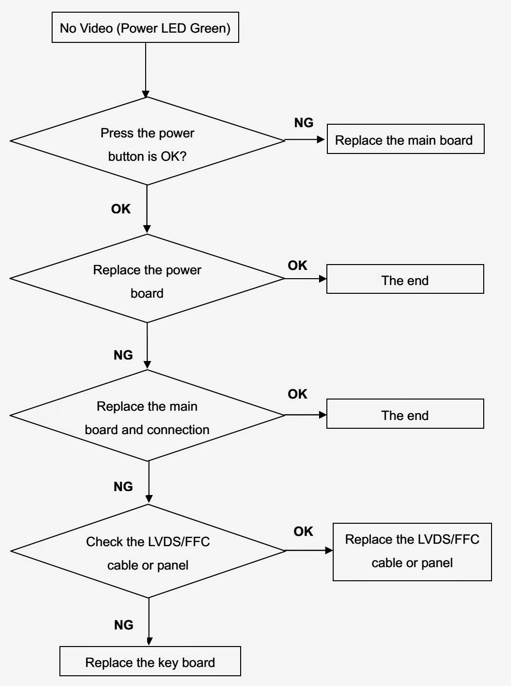
No video_Power LED Green

TOSHIBA NOTEBOOK (LAPTOP) - PROBLEMS and CHECKS - 1

$
0
0
PROBLEMS
Some problems you may encounter when using your notebook computer are relatively easy to identify and solve. Others may require help from your dealer, your network administrator or the manufacturer of a software program.
Program stops responding.
If you are working with a program that suddenly freezes all operations, chances are the program has stopped responding. You can exit the failed program without shutting down the operating system or closing other programs.
To close a program that has stopped responding:
1 Press  Ctrl, Alt, and Del simultaneously (once).
2 Click the Applications tab.  If a program has stopped responding, the words “not responding” appear beside its name in the list.
3 Select the program you want to close, and then click End Task.  Closing the failed program should allow you to continue working. If it does not, continue with step 4.
4 Close the remaining programs one by one by selecting the program name, then End Task.
5 Turn off your computer according to the instructions.
Program performs an illegal operation.
If you receive the message, “Your program has performed an illegal operation, “you should record the details of the message and consult the software manufacturer.
To record the details:
1 Click the Details button and select the text the operating system displays.  The Details button displays information that the software manufacturer needs to help you solve your problem.
2 Press Ctrl and c simultaneously to copy the text to the clipboard.
3 Open Notepad (click Start, point to All Programs, and then point to Accessories and click Notepad).
4 Press Ctrl and v simultaneously to paste the details into Notepad.
5 Add a paragraph break and type some notes describing what you were doing when you received the message.
6 Save the file and refer to it when you contact the software manufacturer.
Problems to turn on the computer
These problems may occur when you turn on the power. The computer will not start.  
Make sure you attached the AC adapter and power cable properly or installed a charged battery.
Press and hold down the power button for a few seconds.
If you are using the AC adapter, check that the wall outlet is working by plugging in another device, such as a lamp.
The computer starts but, when press a key, nothing happens.
Probably in Standby mode and have a software or resource conflict. When this happens, turning the power on returns you to the problem instead of restarting the system.
To clear the condition, press Ctrl, Alt, and Del simultaneously.
Clearing the condition may get the computer running, but it won’t solve a resource conflict.
The computer is not accessing the hard disk or the diskette drive.
Computer normally loads the operating system from the hard disk. If you have a hard disk problem, you will not be able to start the computer. Insert a system diskette into the diskette drive, press the left or right arrow key and choose your boot-up device.
HINT: Press F12 as you power on the computer to access the menu.
The computer displays the WARNING RESUME FAILURE message.
The computer was placed in Standby mode and the battery has discharged. Data stored in the computer’s memory has been lost.
To charge the battery, leave the computer plugged into a live wall outlet for several hours.
The computer displays the Non-System disk or disk error message.
Make sure there is no diskette in the diskette drive. If there is one, remove it and press any key to continue. If pressing any key does not work, press Ctrl, Alt, and Del to restart the computer.
The Windows operating system is not working
Once you are familiar with the desktop and used to the way the operating system responds to your work routine, you can easily detect if the operating system is not working correctly.
For example:
 The operating system fails to start after the Starting Windows XP message appears.
 The operating system takes a long time to start.
 The operating system responds differently from the normal routine.
 The screen does not look right.
Unless a hardware device has failed, problems usually occur when you change the system in some way such as installing a new program or adding a device.
If you experience any of these problems, use the options in the Start-up menu to fix the problem.
Using Start-up options to fix problems
If the operating system fails to start properly, you may have to change your system’s configuration or verify the start-up procedure to fix the problem. To do this, use the options in the Startup menu. This section describes each option and when to use the procedure.
To open the Start-up menu:
1 Restart your computer.
2 Press F8 When your computer starts.  The Windows Advanced Options menu displays these options:
Safe Mode
 Safe Mode (with Networking)
 Safe Mode (with Command Prompt)
 Enable Boot Logging
 Enable VGA Mode
 Last known good configuration (your most recent settings that worked)
 Directory Services Restore Mode (Windows domain controllers only)
 Debugging Mode
 Start Windows normally
 Reboot
 Return to OS Choices (menu)
TECHNICAL NOTE: If your computer is connected to a network, the Start-up menu may display different versions of Safe mode.
Internet problems
Internet connection is very slow.
Many factors contribute to the speed with which you can surf the Internet. They include: modem speed, time of day (when everyone else is surfing, your access can be slow) and popularity of the site. If accessing a particular site is very slow, try later.
Browser can’t find the URL address I typed in.
Make sure you separated the domain names of the address with the forward slash (/). Check the spelling of each name and the syntax of the address carefully. A single incorrect letter or missed character, comma instead of period (“dot”) or other mistake makes it impossible for your browser to locate
the site.
Browser can’t find a site I bookmarked.
The World Wide Web is constantly changing. A site you bookmarked yesterday may not be available today or its server may be down for temporary repair. 
Try again later.
Resolving a hardware conflict
If you receive an error message telling you there is a device driver conflict or a general hardware problem, try using Windows Help and Support to troubleshoot the problem first.  For help on hardware conflicts:
1 Click Start, then click Help and Support.
2 Click the Hardware link in the window’s left pane.  A list of category links appears.
3 Click the Fixing a hardware problem.
4 Choose from specific topics and follow the steps.
If there is still a problem, the operating system should display a message that explains what the conflict is.
Resolving hardware conflicts on your own
Computer components need resources to accomplish a task. A device, such as a disk drive or a modem, needs a channel to the computer’s Central processing Unit (CPU). It also needs a direct channel to the computer’s memory to store information as it works. These channels of communication
are commonly referred to as system resources.
Interrupt Request Channel
The channel to the CPU is called an Interrupt Request (IRQ) because it interrupts what the processor is doing and requests some of the processor’s time. If two or more devices use the same IRQ, the processor does not know which device is asking for attention. This may cause a hardware conflict.
NOTE: One of the IRQs may be shared by multiple devices. This is called IRQ sharing and is normal.
Direct Memory Access
Similarly, the data required by the device is stored in a specific place or address in memory called the Direct Memory Access (DMA). The DMA provides a dedicated channel for adapter cards to bypass the microprocessor and access memory directly. If two or more devices use the same DMA, the data required by one device overwrites the data required by the other, causing a hardware conflict.
Resolving conflicts
There are three things you can do to resolve hardware conflicts:
Disable the device.  
For an older device, remove it from the computer.
Disable another system component and use its resources for the new device.
Fixing a problem with Device Manager
Device Manager provides a way to check and change the configuration of a device.
CAUTION: Changing the default settings using Device Manager can cause other conflicts that make one or more devices unusable. Device Manager is a configuration tool for advanced users who understand configuration parameters and the ramifications of changing them.
Disabling a device
1 Click Start, Control Panel, Performance and Maintenance, Administrative Tools.
2 Double-click the Computer Management icon.
3 In the left pane, click Device Manager.
4 Select the specific device from the device category.
5 In the toolbar, look to the far right for an icon of a monitor with a strike mark through a circle on the front. This is the disable feature.
6 Click the icon.  You are given the option of disabling the device.
7 Click yes or no, whichever is appropriate.
Checking device properties
Device Manager provides a way to view the properties of a device. Properties include the name of the manufacturer, the type of device, the drivers installed, and the system resources assigned to the device.
To check a device’s properties:
1 Click Start, Control Panel, Performance and Maintenance, Administrative Tools.
2 Double-click the Computer Management icon.
3 In the left pane, click Device Manager.
4 To view the device(s) installed, double-click the device type.
5 To view the properties, double-click the device.  The operating system displays the Device Properties window, which provides an array of tabs. They include:
The General tab, which provides basic information about the device.
The Resource tab, which lists resources assigned to the monitor, DVD-ROM, DVD-ROM/CD-RW, diskette drive, and other power-using functions.
The Drivers tab, which displays the drivers being used by the device.
A Troubleshooting button is also present.
Click troubleshooting.
A Help and Support window for that device appears.

LAPTOP and DESKTOP COMPUTER PROBLEMS - 2

$
0
0
PROBLEMS
Memory module problems
Incorrectly connected or faulty memory modules may cause errors that seem to be device-related. It is worthwhile checking for these first:
1 Turn off your computer according to the instructions.
2 Remove the memory module
3 Reinstall the memory module and making sure it is seated properly.
4 Check for the error again.
5 If the error recurs, remove the memory module entirely and check for the error again.
If removing the memory module eliminates the error, the memory module may be faulty. If the error recurs without the memory module installed, the error is not caused by the memory module.
Power and the batteries
Your computer receives its power through the AC adapter and power cable or from the system batteries (main battery and real-time clock (RTC) battery). Power problems are interrelated. For example, a faulty AC adapter or power cable will neither power the computer nor recharge the batteries.
Here are some typical problems and how to solve them:
Make sure the AC adapter and power cable are firmly plugged into both the wall outlet and the computer.  If the AC power light still does not come on, check that the wall outlet is working properly by plugging in a lamp or other appliance.  The main battery may not be inserted correctly in the computer. Turn off the computer, remove the battery, clean the contacts with a soft dry cloth (if necessary) and replace the battery.
The battery may be too hot or too cold to charge properly. If you think this is the probable cause, let the battery reach room temperature and try again.
If the battery has completely discharged, it will not begin charging immediately. Leave the AC adapter and power cable connected, wait 20 minutes and see if the battery is charging.  If the battery light is glowing after 20 minutes, let the computer continue charging the battery for at least another 20  minutes before you turn on the computer.
If the battery light does not glow after 20 minutes, the battery may have reached the end of its useful life. Try replacing it.
The battery appears not to power the computer for as long as it usually does.
If you frequently recharge a partially charged battery, it may not charge fully. Let the battery discharge completely, and then try charging it again.  
Check the power options using the Power Management utility. 
Have you added a device, such as a PC Card or memory module, that takes its power from the battery? 
Is your software using the hard disk more? 
Is the display set to turn off automatically? 
Was the battery fully charged to begin with? 
All these conditions affect how long the charge lasts.
Keyboard problems
If, when you type, strange things happen or nothing happens, the problem may be related to the keyboard itself.  The keyboard produces unexpected characters.  A keypad overlay may be on. If the numeric keypad or cursor control light is on, press Fn and F10 simultaneously to turn off the cursor control light or press Fn and F10 Simultaneously to turn off the numeric keypad light.  If the problem occurs when both the keypad overlays are off, make sure the software you are using is not remapping the keyboard. Refer to the software’s documentation and check that the program does not assign different meanings to any of the keys.
You have connected an external keyboard and the operating system displays one or more keyboard error messages.
If you have a second keyboard, try it. If it works, the first keyboard may be defective or incompatible with your computer.
Display problems
Here are some typical display problems and their solutions:
The display is blank.
Display Auto Off may have gone into effect. Press any key to activate the screen.
You may have activated the instant password feature by pressing Fn and F1 simultaneously. If you have registered a password, press the Enter key, type the password and press Enter. If no password is registered, press Enter. The screen reactivates and allows you to continue working.
If you are using the built-in screen, make sure the display priority is not set for an external monitor. To do this, press Fn and F5 simultaneously (once). If this does not correct the problem, press Fn and F5 simultaneously again to return the display priority to its previous setting.
If you are using an external monitor:
Check that the monitor is turned on.
Check that the monitor’s power cable is firmly plugged into a working power outlet.
Check that the cable connecting the external monitor to the computer is firmly attached.
Try adjusting the contrast and brightness controls on the external monitor.
Press Fn and F5 simultaneously to make sure the display priority is not set for the built-in screen.
Screen does not look right.
You can change the display settings by clicking a blank area of the desktop with the secondary control button, then clicking Properties. This displays the Display Properties window. The Appearance tab of this window allows you to choose the colors for the screen. The Settings tab allows you to choose the screen resolution.
The built-in screen flickers.
Some flickering is a normal result of the way the screen produces colors. To reduce the amount of flickering, try using fewer colors.
To change the number of colors displayed:
1 Point at the desktop and click with the secondary button.
2 Click Properties, and then the Settings tab.
3 Change the Colors option and click OK.
A message tells you that there is a problem with your display settings and that the adapter type is incorrect or the current settings do not work with your hardware.  Reduce the size of the color palette to one that is supported by the computer’s internal display.
To change the display properties:
1 Point at the desktop and click with the secondary button.  The Display Properties window appears.
2 Click Properties, then click the Settings tab.
3 Adjust the screen resolution and/or color quality.
4 Click OK.
The display mode is set to Simultaneous and the external display device does not work.  Make sure the external monitor is capable of displaying at resolutions of 800 x 600 or higher. Devices that do not support this resolution will only work in Internal/External mode.
Disk drive problems
Problems with the hard disk or with a diskette drive usually show up as an inability to access the disk or as sector errors. Sometimes a disk problem may cause one or more files to appear to have garbage in them. Typical disk problems are:
You are having trouble accessing a disk, or one or more files appear to be missing.
Make sure you are identifying the drive by its correct name (A: or C:).
Error-checking
Run Error-checking, which analyzes the directories, files and File Allocation Table (FAT) on the disk and repairs any damage it finds:
To run Error-checking:
1 Click Start, then click My Computer.
2 Right-click the drive you want to check and click Properties.
The drive’s properties box appears.
3 Click the Tools tab.
4 Click the Check now button.  The Check Disk All Apps box appears.
5 You can choose one or both options:
Automatically fix file system errors
Scan for and attempt recovery of bad sectors
6 Click Start.
Error-checking runs the test.
Hard disk seems very slow.
If you have been using your computer for some time, your files may have become fragmented. Run Disk Defragmenter.
To do this, click Start, then click All Programs, point to Accessories and System Tools, and click Disk Defragmenter.
Data files are damaged or corrupted.
Refer to your software documentation for file recovery procedures. Many software packages automatically create backup files.
You may also be able to recover lost data using utility software, which is available from your dealer.
Some programs run correctly but others do not.
This is probably a configuration problem. If a program does not run properly, refer to its documentation and check that the hardware configuration meets its needs.
DVD-ROM or DVD-ROM/CD-RW drive problems
You cannot access a disc in the drive.
Make sure the drive tray has closed properly. Press gently until it clicks into place.
Open the drive tray and remove the disc. Make sure the drive tray is clean. Any dirt or foreign object can interfere with the laser beam.
Examine the disc to see whether it is dirty. If necessary, wipe it with a clean damp cloth dipped in water or a neutral cleaner.
Replace the disc in the tray. Make sure it is lying flat, label side up. Press the disc down until it locks on the spindle.
Close the drive tray carefully, making sure it has shut completely.
Press the disc eject button, but the drive tray does not slide out.
Make sure the computer is connected to a power source and turned on. The DVD-ROM or DVD-ROM/CD-RW drive eject mechanism requires power to operate.
To remove a disc without turning on the computer, use a narrow object, such as a straightened paper clip, to press the manual eject button. This button is in the small hole next to the disc eject button on the right side of the computer.
Some discs run correctly, but others do not.
If the problem is with an application CD-ROM, refer to the software’s documentation and check that the hardware configuration meets the program’s needs.  The color of the materials used to make the disc can affect its reliability. Silver-colored CD-ROMs are the most reliable, followed by gold-colored CD-ROM. Green-colored CDROMs are the least reliable.
WinDVD problems: general issues
WinDVD has been configured to provide optimum performance and quality based upon your system’s available resources. Changes made to the system or its configuration may impact the playback performance of the WinDVD player.
WinDVD controls are disabled.
Controls may be grayed out by commands on the DVD disc. For example, it is common for DVD movie titles to disable fast-forward and rewind during the legal notices at the beginning of a movie.
Playback performance is poor.
Make sure your system’s A/C adapter is plugged in and the system’s power setting is on full.
The Root or Title menu does not open.
Most DVD titles have one or both of the “Root” and “Title” menus. If one menu button appears to do nothing, try the other menu button.
WinDVD performance decreases after making a system change.
DVD playback performance is dependent upon several system resources. Changes to these system resources caused, for example, by installing a new graphics or audio card may impact performance. Some software changes may also impact playback performance (for example, downloading new drivers from the Web). Before installing a new hardware or software component on your system, check for any potential conflicts between its resource requirements and your current system configuration. Also, if you change your operating system, check with your PC manufacturer or your graphics card vendor to ensure that you have the appropriate drivers for both your hardware (for example, the graphics card) and software (drivers must support the operating system and DVD with WinDVD).
Slow playback performance.
DVD playback is a resource intensive application. Other applications and/or changes to your system hardware, software or configuration can impact playback performance. If playback is slower than normal, try:
1 Closing any other open applications to improve the performance of the DVD playback.
2 Ensuring DMA (Direct Memory Access) is turned on.
3 If you have installed new hardware (such as a new graphics card or audio card), ensure the component’s drivers support Microsoft DirectX 8.1 or higher and WinDVD. Contact the manufacturer of the component.
4 Verifying that your display driver resolution, color depth and refresh rate are optimal for DVD playback. (Some systems do not support video overlays if these parameters are not optimal.) Try lowering these settings to improve performance.
If Something Goes Wrong
Resolving a hardware conflict
Secondary IDE Channel DMA setting
To ensure the Secondary IDE Channel DMA setting:
1 Click Start, Control Panel, Printers and Other Hardware, System.  The System Properties window.
2 Click the Hardware tab.
3 Click the Device Manager button.
4 Click + to open the IDE ATA/ATAPI Controllers.
5 Double-click the Secondary IDE Channel.  The Secondary IDE Channel Properties window appears.
6 Click Advanced Settings.
7 Look at Device 0. The current transfer mode should be Ultra DMA Mode 2. If it isn’t, select Ultra DMA Mode 2 from the pull-down menu and click OK.
WinDVD problems: content issues
Movies exhibit poor performance of “Director's Commentary” or other similar optional content versions.  Some movies may exhibit poor performance of these features. In particular, the video portion of the movie may become jerky or show pauses. The normal version of the movie will not show this problem.
WinDVD will not function properly with “debug” software installed.  The WinDVD application will not function properly if it detects that debug software is present on the system. Remove the debug software to restore functionality of WinDVD.
Refer the previous post here for more

SANYO 19R30 - LCD TV - SERVICE MODE - SOFTWARE UPGRADE

$
0
0
How to enter Service Mode _ Software Upgrade _ Power Supply [SMPS] & Back-light Schematics (Circuit Diagrams) _ SANYO 19R30 - 19" LCD TV [STR-Y6453]
Service Mode [Factory Mode]
* First press “INPUT” button, then in turn press “2 - 5 - 8 - 0” to access factory main menu. 
* Press ▲/▼ to select item, then press to access. 
* Press ▲/▼ to move upward or downward and select item. 
* Press ◄/►   to adjust.
* Press “MENU” to return to the previous screen.
Software upgrade method
* Copy the provided “KU*.bin” file to USB device root category. Then change the file name to “ku19p.bin” or “KU19P.BIN”.  
* Completely cut off the TV power by unplug the power cord from the power outlet. (Be sure to use buttons on the remote control or on the TV to completely discharge the TV after power off).
* Insert the USB device into the USB port. Keep holding any button (except POWER button) on the TV and then plug the power cord into the power outlet, after about 2-3s release the button, the software begins to upgrade automatically. Note that during upgrade the USB device cannot be removed and the TV cannot be power off. 
* During the process operate according to hints provided on the screen. When complete, remove the USB device, unplug the power cord and then plug it again, then press POWER to turn on the TV.
* After software upgrade the TV must be performed initialization and ADC correction and white balance alignment again. Below are steps for initialization:
* Go to factory menu, select the third item “Feature & Adjust”.
Go to “Feature & Adjust” sub-menu, select “EEPROM Init” at the first line. 
Press (RIGHT arrow button) to perform initialization. During the process the message “Please Wait” will be displayed. When complete, “OK” is displayed.
SMPS SCHEMATIC [CLICK ON THE PICTURES TO MAGNIFY]
BACK-LIGHT INVERTER


TROUBLESHOOTING - SANYO LCD-19R30 - 19" LCD TV

$
0
0
No raster_Sound normal, but no picture_ Picture normal, but no sound_Some source channel work abnormally.
No raster (screen is not lit), no picture, no sound
  If detect NS01 (main chip) pin 169 is of high level, you may remove RS14, detect VS01 emitter if first output high level after power on, then output low level continuously. If not, the reset circuit may have problem. First detect if NS01 (main chip) pin 44 waveform is sine wave, if not, check NS01 crystal oscillator circuit. When checking periphery of NS01, NS02 and NS05, check relative component’s welding, then use oscilloscope to detect the joint resistor pin between NS01 and  NS05.  If  the  waveform  is  not  regular  square-wave,  that  means  either  NS01  or  NS05  work abnormally and therefore cause address line and data line be in error. NS05 error probability is greater. In addition, if joint resistor between NS01 and NS05 is in error, it will also cause no raster, no picture and no sound.
CLICK ON THE PICTURES TO ZOOM IN
Sound is normal, but no picture.  (Blue screen and OSD can be displayed.)  Note: HDMI channel is excluded.
Sound OK, but no picture (only backlight lights up)
Picture normal, but no sound.
Some source channel work abnormally.
Note:To get normal HDMI picture, especially when connect to DVD player with HDCP information, it must be guaranteed that NV04 and NV05 (HDMI port DDC chip) writing is correct, and especially bus between NV04, NV05 and HDMI jack must be smooth and unhindered. Secondly HOTPLUG circuit must be guaranteed (it is of high level at normal broadcast), otherwise the picture playback cannot be normal.
To get normal HDMI sound, especially when connect to DVD player with HDCP information, it must be guaranteed that NV04 and NV05 (HDMI
port DDC chip) writing is correct, and bus between NV04, NV05 and HDMI jack must be smooth and unhindered, otherwise the sound playback cannot go.

HOW TO ENTER SERVICE MODE - SHARP LC-32LE240M - LED LCD TV

$
0
0
Applicable to SHARP LC-32LE240M/340M (For Asia, Indonesia, Vietnam, Thailand, Middle East)
LC-32LE240M/340M (For Philippines) [NTSC]
ADJUSTMENT MODE [SERVICE MODE]
Entering and cancel the adjustment process mode
 While holding down the TV/VIDEO and Volume DOWN keys at the same time, plug in the AC cord to turn on the power. (“K” standing for inspection process mode is displayed on the upper left position of the screen.)
* Press the Channel DOWN and Volume DOWN keys at the same time. (The adjustment process mode screen appears.)
* To cancel it, turn off the power using the Power switch or remote control.
Remote controller key operation and description of display in adjustment process mode.
CLICK ON THE PICTURES TO ZOOM IN
Software upgrading.
Main Software Package.
1) Plug off the LCD TV.
2) Insert the USB device to the USB terminal at the LCD TV. (Make sure that the latest software is installed in the USB device).
3) Hold the LCD TV power key and plug on the LCD TV.
4) LCD TV is on and detecting the USB device.
5) A few seconds later, the software upgrading will start automatically.
6) Let the process running & entering verification.
7) Software is successfully installed when the following appears at the end of the process.
8) Plug off the LCD TV and plug ON again as usual.
9) LCD TV is running with the latest software.
Factory setting
AC power is plug off after shipment setting is done.
CAUTION: Do not plug on again after shipment setting is done. If do, please re-do the shipment setting. Do not off with remote control.
USB Clone (Smart Loader)
The Smart Loader is a function implemented in the service software to easily replicate the user settings of one TV into another. These settings include (but not restricted to): picture and audio, turning set-up, language and country selection, PIN, child locked programs etc.  Factory adjustments are not copied as they are different for every TV.
The Smart Loader makes possible the user data to be stored in a memory device connected to the USB terminal of the TV that is used as reference and later load those data into other TVs by using their respective USB terminal.
* Enter USB clone menu (Smart Loader)
* Press panel key [TV/VIDEO] and [VOL+] and AC on, it will go to password entry OSD.
* Enter digit “369” then it will go to Smart Loader Menu.
Smart Loader function
SMLD Store
To copy all related data from TV > USB and put under a fixed filename “SHP_SMLD.bin” (8kB).
SMLD Restore
To restore the related data from USB > TV.
SMLD Store and Restore execution
To execute SMLD Store or SMLD Restore, highlight at selected item and press Enter.
When copying is in process, “WAIT” is displayed.
After cloning process is done, “OK” is displayed.
If cloning process is not finished due to error (e.g. no pen drive detected), “NG” is displayed.
Exit USB Clone menu (Smart Loader)
To exit Smart Loader menu, plug off AC Cord.
EDID DATA INPUT

HOW TO ENTER SERVICE MODE - ONIDA CTVs - SMPS Circuit Diagram

$
0
0
ONIDA COLOUR TELEVISION – 14XS / 20XS / 21IQ/ 14TVE / 20TVE / 21TVE/ 21BLACK FGL (FTG)/ 21FLAT3G
SERVICE MODE
NB:You should have its original remote control to enter Service Mode and adjust the data values.  No Universal remote control, or others can be used for this purpose.
* The following display comes on the screen by pressing DISPLAY key and VSM key at the same time.
** [For Model: 21XSW4 Series: Press "VSM" and "+" On remote control.]
[1] FACTORY
[2] SERVICE  MODE
* Press CURSOR UP OR DOWN key to be in Service menu.
* To select Service Menu parameters use CURSOR ▲/▼ key and to adjust these parameters use CURSOR ◄/► key.
H-LINE
1.To get H-line press VSM and DISPLAYSimultaneously.
2. Press CURSOR UP KEY to get R CUTOFF.
3. Press '0' to get H-line.
4. To come out of H-line again press '0'.
VSM PRESET
There is FOUR VSM
PRESETS. (CARTOON,FILM/POP,NEWS,)
For the setting of individual VSM PRESETS
1.  Press VSM and DISPLAY at the same time.
2. Press CURSOR DOWN key to get the Setting for the
VSM PRESET.
3.  Press CURSOR DOWN key for the selection of each parameter.
4.  Use CURSOR LEFT/RIGHT key for their setting as per the table given below.
5.  Press VSM Key for selection of VSM PRESETS.
A. Digits specified for the various parameters (not specified as FIX) are closer to the values to be adjusted. The final adjustment should be as per the procedure specified.
B. Digits mentioned in the Service Menu should not be changed wherever ‘Fix’ is mentioned, elsewhere they are subject to change as per procedure specified
SMPS SCHEMATIC
CLICK ON THE PICTURES TO MAGNIFY

SONY HCD-EX660Z - SCHEMATIC (Circuit Diagram) _ SMPS and AMPLIFIER

$
0
0
SONY HCD-EX660Z
Russian Model HCD-EX660Z/EX990Z
E Model HCD-EX660Z/EX880Z/EX990Z
Mexican Model HCD-EX880Z/EX990Z
South African Model HCD-EX660Z
SCHEMATICS [Click on the Circuit Diagrams to Zoom In]
PWB
Power Amp Circuit & PWB

ERROR CODES - SONY HCD-EX660Z - FAULTS - Protection Modes

$
0
0
TEST MODE & Error Codes & Descriptions: SONY HCD-EX660Z/EX880Z/EX990Z
Russian Model: HCD-EX660Z/EX990Z
E Model: HCD-EX660Z/EX880Z/EX990Z
Mexican Model: HCD-EX880Z/EX990Z
South African Model: HCD-EX660Z
HCD-EX660Zis the amplifier, USB, CD player and tuner section in MHC-EX660.
HCD-EX880Zis the amplifier, USB, CD player and tuner section in MHC-EX880.
HCD-EX990Zis the amplifier, USB, CD player and tuner section in MHC-EX990.
Amplifier section
The following are measured at Mexican model: AC 120 V – 240 V, 60 Hz
Other models: AC 120 V – 240 V, 50/60 Hz
MHC-EX990
Front Speaker: Power output (rated): 100 W + 100 W (at 2 ohms, 1 kHz, 1% THD)
RMS output power (reference): 180 W + 180 W (per channel at  2 ohms, 1 kHz) Subwoofer:
RMS output power (reference): 360 W (at 4 ohms, 100 Hz)
MHC-EX880
Power output (rated): 140 W + 140 W (at 3 ohms, 1 kHz, 1% THD)
RMS output power (reference): 240 W + 240 W (per channel at  3 ohms, 1 kHz)
MHC-EX660
Power output (rated): 85 W + 85 W (at 4 ohms, 1 kHz 1% THD)
RMS output power (reference): 150 W + 150 W (per channel at 4 ohms, 1 kHz)
RELEASING THE DISC TRAY LOCK
  The disc tray lock function for the anti-theft of a demonstration disc in the store is equipped.
1.Press the [Power] button to turn the power on.
2.Press the [FUNCTION] button to select CD function.
3.Press the [Stop] and [Eject] button simultaneously and hold down for around 5 seconds.
4.The message “UNLOCKED” is displayed and the disc tray is unlocked.
Note: When “LOCKED” is displayed, the slot lock is not released by turning power on/off with the [Power] button.
TEST MODE
  The cold reset clears all data including preset data stored in the memory to initial conditions. Execute this mode when returning the set to the customer.
Procedure:
1.In standby status, press the [Power] button to turn on the system.
2.Press three buttons of [Stop], [OPTIONS] and [Power] simultaneously.
3.When “RESET” appears, the set enters standby status.
COMMON TEST MODE
This mode is used to check operations of the Amplifier section.
Procedure:
1.To enter Common Test Mode, press three buttons of [FUNCTION],[OPTIONS] and [Stby/Power] simultaneously.
2.“COMMON” appears on the liquid crystal display panel. The volume is changed to VOLUME MIN.
Check of Amplifier
1.Press the [EQ] button repeatedly until a message “EQ MAX”appears on the liquid crystal display panel. EQ increases to its maximum.
2.Press the [EQ] button repeatedly until a message “EQ MIN” appears on the liquid crystal display panel. EQ decreases to its minimum.
3.Press the [EQ] button repeatedly until a message “EQ FLAT” appears on the liquid crystal display panel. EQ is set to flat.
4.When the [VOLUME] knob is turned clockwise even slightly, the message “VOL 29” (for EX660Z and EX880Z) or “VOL 31” (for EX990Z) appears on the liquid crystal display panel. Sound is set to Standard Volume Position (SVP).
5.When the [VOLUME] knob is turned clockwise even slightly, the message “VOL MAX” appears on the liquid crystal display panel. Sound is set to volume maximum.
6.When the [VOLUME] knob is turned counterclockwise even slightly, the message “VOL MIN” appears on the liquid crystal display panel. Sound is set to volume minimum.
3.To release from this mode, press the [Stby/Power] button.
4.The cold reset is enforced at the same time.
CD THEFT PREVENTION
  This mode let you lock the disc tray. When this mode is activated, the disc tray will not open when the [Eject] button is pressed. The message “LOCKED” will be displayed on the liquid crystal display panel. This mode only applied when there is disc on the tray.
Procedure:
1.In standby status, press the [Stby/Power] button to turn the power on.
2.Press the [FUNCTION] button to select CD function.
3.Press the [Stop] and [Eject] button simultaneously and hold down for around 5 seconds until “LOCKED” or “UNLOCKED” is displayed on the liquid crystal display panel.
TUNER STEP CHANGE
The step interval of AM channels can be toggled between 9 kHz and 10 kHz. This mode is not available for Saudi Arabian, European and Russian models.
Procedure:
1.Press the [Stby/Power] button to turn on the system.
2.Press the [FUNCTION] button repeatedly to select the “AM”.
3.Press the [Stby/Power] button to turn off the system.
4.Press the [DISPLAY] button on the remote control to enter clock mode or demo mode, then press the [TUNING + M L] and [Stby/Power] button simultaneously.
5.The system turns on automatically. The message “9K STEP” or “10K STEP” appears on the liquid crystal display panel and thus the channel step is changed.
PROTECT KIND CHECK TEST MODE
  This mode is used to check type of protect occurred during protector on.
Procedure:
During protection on, LCD will toggle between “PROTECT EXX” message & protector kind message display.
PROTECT E01> Defect of AMP circuit & SMPS overload.
PROTECT E02> Defect of fan, output speaker, 7V regulator & 9V regulator circuit.
OVER CURRENT > Defect of power supply circuit to 5V regulator (USB).
Defect of AMP circuit
  If PROTECT mode is in “PROTECT ERROR 01”, the following defect can be considered;
* OTP (Over Temperature Protection)> Unusual heat of MOSFET by assemble defect of heat sink and destruction of MOSFET etc.
* Unusual output of Power mount > the power mount is unusual output.
* SMPS overload > Current surge to MOSFET by MOSFET and defect of PS output line.
  If output does not come out even if the set status is not in PROTECT mode The following defect can be considered;
* Under Voltage > SMPS switching MOSFET defect.
* RESET defect > Reset signal status from micom is not ‘H’.
Defect of power supply (regulator)
If the PROTECT mode is “PROTECT ERROR 02”, the following defect can be considered;
* OCP (Over Current Protection)> Unusual output voltage of 7V & 9V regulator short.
* Fan block > Fan supply draw current.
* DC Detection > DC appears in SP terminal by defect of AMP IC and MOSFET or output of short-circuit.

harman / kardon DVD 25 - SMPS SCHEMATIC [Circuit Diagram] (NDV8501 - NDV8601)

$
0
0
harman/kardon NDV8501 / NDV8601 Based Progressive Scan DVD Player
Model Number: DVD25
Compactable with CD as well as DVD with Region Code ‘0’ or ‘2
SMPS SCHEMATIC [Click on the pictures to Zoom In]
To reset the unit
* Set the unit in SY-BY.
* Push “Clear” button on the remote control, until the unit Power ON. [This will not change the Zone]
To read the software version.
* Set the unit in ON mode.
* Push Set-up button on the remote control.
* Push ‘1211’, and then a new menu showing the data of the unit.
To Exit, push Set-up.

Blu-ray Player - HARMAN KARDON - BDT 3/120V and BDT 30/240V _ Power Supply Circuit Diagram

$
0
0
Power supply [SMPS] Schematic _ harman/kardon Blu-ray player BDT-3 & BDT-30
SMPS SCHEMATIC (Click on the pictures to zoom in)
COMMON PROBLEMS
The player won’t power up (the Power indicator is not lit):
*Check that the player’s Ac power cord is properly plugged into the player’s Power cord connector.
* Check that the player’s Ac power cord is plugged into a working Ac out let and that the Ac outlet is not controlled by a switch.
* Make sure that the Master Power switch (on the player’s rear panel) is in the “On” position.
The disc does not play:
* Check that the disc is inserted correctly (label side up).
* Check that the disc is the correct type: Bd-video (single-layer or double-layer), DVD-video, DVD +R/+RW, DVD-R/-RW, cd dA (cd digital audio), cd-R/RW.
Other disc types will not play.
No picture:
* Check the connection between the player and the TV.
* Check that the TV is turned on and that it is set to the correct input source.
* Confirm that all of the choices made in the display settings menu are correct for your TV.
* Check that the TV is hdcP-compliant. The player cannot be used with a TV that is not hdcP-compliant.
No sound:
* Check that the HDMI and/or coaxial digital connections are properly made.
* If you’re using the coaxial digital connection, check that the digital audio settings on the connected device have been properly set.
* If you’re using only the HDMI connection, check that the HDMI audio settings on the connected device have been properly set.
* If you’re using only the HDMI connection, check that the BDT 3/BDT 30’s HDMI Audio Output is set to “On.
The picture appears in the wrong aspect ratio:
Change the Aspect Ratio setting in the display settings menu to match the TV.
There is noise or other interference in the picture while playing a Blu-ray disc recording or DVD:
Check that the disc surface is clean and not scratched.
Cannot access media on a connected USB device:
• check that the device is formatted in the FAT32 file system. Other file systems are not compatible with the BDT 3/BDT 30.
The player does not respond to remote-control commands:
* Replace both remote-control batteries with fresh ones, and make sure that they are installed correctly.
* Hold the remote control closer to the player.
* Check that the player’s remote sensor is in the remote control’s line of sight.
* Make sure that the protective shipping film has been removed from the player’s front panel.
The player does not respond to commands, or it behaves in an erratic way:
* Unplug the player’s power cord from the AC outlet, wait 30 seconds, and plug it back in.
* TheØ symbol appears on the screen when you press a remote-control button:
* The selected function is not permitted at the time you press the button.


HP LCD TV - LT3700 - LT4700 - LED BLINKING CODES - HOTEL MODE - PANEL FAULTS

$
0
0
HP LT3200, LT3700, LT4200, LT4700 High-Definition LCD TV - LED Blinking Codes & Panel Faults - Hotel Mode _ Software version
LED indicators
  Special condition to watch out for with the following message: Red LED blinking 2 sec interval – Digital Demodulator does not respond.
Error code 003 (digital demodulator does not respond) requires source to be selected as “antenna” before the test is valid. If source is not antenna, it will always give you error code 003 because digital demodulator is not turned on until “antenna” source is selected.
Software version information.
To access the software version information OSD:
1 Turn the TV on.
2 Press the Menu button.
3 From OSD, select Setup => Time.
4 Press the following keys: SAP/MTS => 7 => 7 => 7. The software version information displays on the lower right corner of the TV.
To run diagnostics
1 Power off the TV and pull disconnect the power cord.
2 Plug in the power cord while holding the power button on the TV (noton the remote). Hold the power button until a testing message appears. This may take up to 30 seconds.
3 Diagnostic tests begin.
To get back to normal TV operation after running diagnostics
1 After the diagnostic test finishes, power off the TV and disconnect the power cord.
2 Wait for about 30 seconds; and then plug the power cord back in. The TV returns to normal mode.
Installation menu
  The installation menu allows you to change default setting values of current input audio and video modes. For example, to change the picture settings for a component input, switch the TV source to component before entering this mode.
To access the Installation menu:
1 Turn the TV on.
2 On the remote, press the Menu button.
3 From the OSD, select Setup => Time.
4 If the TV is NOT in Hotel mode, press the following key sequences: SAP/MTS => 1 => 3 => 5.
5 If the TV is in Hotel mode, change input source to AV2, then press SOURCE=> 1 => 3 => 5.
Color adjustments in this menu apply to ALL modes (Cool, Standard, or Warm). If you want to adjust the color temperature of a single mode, you will need to adjust the White Balance settings in the Factory Menu.
Hotel mode
To access the installation menu:
1 Run the Setup wizard (or channel scan and time setup) through the main menu.
2 Access the install menu and change to HOTEL mode from Normal TV mode. 
To access the installation menu:
1 Turn the TV on.
2 On the remote, press the Menu button.
3 From the OSD, select Setup => Time.
4 Press the following key sequences: SAP/MTS => 1 => 3 => 5
To return to normal mode from Hotel mode:
1 On the remote, press the Menu button.
2 From the OSD, select Setup => Time.
3 Change input source to AV2, and then press SOURCE => 1 => 3 => 5.
Panel faults
Problem: Line
Solution: Change LCD panel.
Problem: Scrape on the LCD panel
Solution: Change LCD panel or change Polarizer
Problem: Mura (cloudiness)
Solution: Change LCD panel
Problem: LCD crack
Solution: Change LCD panel
Problem: Scrape on the LCD panel 
Solution: Change LCD panel

VIEWSONIC A90F - VCDTS23307-2R - SMPS - H-OUT AND V-OUT SCHEMATIC

$
0
0
ViewSonicA90f+-1 _ VCDTS23307-2R - 19” Digital Controlled Color Monitor – SMPS, Horizontal Output & Vertical Output Circuit Diagrams
CLICK ON THE SCHEMATICS TO ZOOM IN
SMPS SCHEMATIC
HORIZONTAL SCAN & OUTPUT
VERTICAL SCAN-OUT
SYSTEM CONTROL & MEMORY
TPW-697 _ POWER TRANSFORMER – 5061369700
TFB-280T _ TRAQNS.FLYBACK COLOR – 5062628031
TFB-280L _ TRAQNS.FLYBACK COLOR – 5062628032
Power supply working frequency - constant between 30.25 kHz and 31.25 kHz, R817A adjust the frequency

HOW TO UPDATE FIRMWARE - VIEWSONC VX910 - Model No.VS10162 - MONITOR

$
0
0
VX910 - Model No.VS10162 - ViewSonic 19” Color TFT LCD Display
FIRMWARE UPDATE PROCEDURE
When you received a received monitor, check whether the firmware version.   If not, follow procedure to upgrade to the latest version.
Equipment needed
* VX710
* PC ( Personal computer )
* LPT cable
* Fixture (LM5ISP)
* Firmware upgrade program.
CONNECTION
To setup ISP environment:
* Hardware: PC or notebook, parallel (printer) cable, ISP tooling.
* Software: If OS was Win2000 or WinXP , install “PORT95NT.exe”
* In order to ensure can execute ISP program, set BIOS in PC or Notebook.
* Double-click the “ PORT95NT.exe” in Windows & install the program.
* Keep on press “Next” (4) times to go through the installation processes.
* Choose “Typical” then press “Next”
* Keep on press “Next” (4) times to go through the installation processes.
Installation completed, restart the PC or notebook.

BIOS SOFTWARE UPGRADE - VIEWSONIC - VX910 19” Color TFT LCD Display.

$
0
0
UPGRADE THE BIOS SOFTWARE - ViewSonic VX910 19” Color TFT LCD Display.

Model No.VS10162
UPGRADE PROCEDURE
After installation, shortcuts may be found in the settings path or the program menu (default setting). [See the previous post here, for more details]
* The security file is a key to use ISP functions; press the "OK" button.
* The warning shown is used to remind the user that a CPU rate that differs from IIC protocol may cause the ISP functions to fail; press the "OK" button.
* As shown in Fig, press the "Create Security File" button to key in a security code, and use the slider bar to adjust the speed of the IIC bus.
* Fig below shows the settings for the ISP software's security code. It requires two command numbers, and the commands must be keyed in sequentially: 7C, 4C, 77. The command numbers and commands must be set by the user while coding. For more details, please refer to section 6 boot code of ISP.
Using ISP to program MCU
* As shown in Fig, select the MTV type first, load the binary or intel hex file to be programmed into the MCU, click "OK," then press the "RUN" button.
* If the user changes the MTV type, the file must be loaded again, as the previously loaded file will be cleared.
* CRC (cyclic redundancy check): the host can check the result in the CRC register instead of reading every byte in flash.
* The Check MCU CRC OK message indicates that the host has verified the program's CRC; see Fig.

VIEWSONIC G90FB-4 Monitor - SMPS - SYSCON and H-OUT - SCHEMATIC (Circuit Diagram)

$
0
0
ViewSonic G90FB-4 - Model No. VS10794 - 19” Digital Controlled Color Monitor - Schematic Diagrams _ Power, Horizontal Out & System control 
Click on the schematics to Zoom In
SMPS
Before check SW.REG
Variable output: 60V 
Constant output: 6.3V, 12V, 83V,180.V, -12V
Adjustment conditions and precautions
Adjustments should be undertaken only on those necessary elements since most of them have been carefully preset at the factory.
  The B+ control block of the SAA4849 has the same behavior as the TDA4856 with adapted threshold voltages. The circuit allows the user to choose the trigger edge of the HDRV signal and the polarity of the output stage via I2C-Bus. The B+ control function block of the SAA4849 consists of an Operational Trans conductance Amplifier (OTA), a voltage comparator, a flip-flop and a discharge circuit. This configuration allows easy application for different B+ control concepts.
Main adjustments:
Power supply Troubleshoot
  The horizontal part contains a PLL, which works over the full frequency range from 25 kHz to 140 kHz. This range can be reduced by a over and an upper frequency limit (Write Once Registers HPMAX and HPMIN).Via I2C bus the number of 48MHz clock cycles is sent through the register. The slewing speed during mode change is also programmable in a write once register (HSLEW) After the clocks for the HPLL are switched on, the HPLL starts with a fixed free running frequency of 60 kHz. The H-drive pulses are not active and the start up procedure is inhibited. The default setting of register bit HCONTROL [0] will cause the HPLL to slew, not switch. To the free running frequency defined in the I2C register HPFREE (the default value is also 60 kHz).Independent on H-syncs which are possibly present. The HPLL will slew to that free running frequency. To achieve an always defined starting point for the startup procedure, this procedure cannot be interrupted.
Horizontal scan & output schematic
Micro-controller Section
  The micro controller (IC101) core is a 80C51 type. The micro clock frequency of 12 MHz is derived from the Xtal oscillator, which is running at 48MHz. The DDC interface is suitable to handle DDC2 by a modified hardware I2C-bus interface .Standard high current ports,3 ADC pouts with voltage inputs and 4 static standard8 bit DAC outputs (low interference) and one PWM output for digital control application are implemented. The central processing unit (CPU) manipulates operands in two memory spaces. These are the 1024byte internal data memory (consisting of 256 bytes standard RAM and 768 bytes AUX-RAM) and 48K-byte internal program memory. The program memory of the SAA4849 consists of 48K bytes ROM. The SAA4849P provides sync. Processing with full auto sync. Capability, a flexible SMPS block and an extensive set of geometry control facilities. Further the IC generates the drive waveforms for DC coupled vertical boosters to the TDA8172.

Viewing all 2033 articles
Browse latest View live


<script src="https://jsc.adskeeper.com/r/s/rssing.com.1596347.js" async> </script>