Quantcast
Channel: Electro help
Viewing all 2033 articles
Browse latest View live

HOW TO OPEN - AOC2241PA 22" LCD MONITOR

$
0
0
DISASSEMBLE PROCEDURE
> Lay down the monitor on the EPE pad (Panel side towards to us), then prize up the decoration piece of front frame use fixture.
> Use hand to draw the decoration piece to take the top of it apart from the block slot of front frame. Use the same method to take apart the other side.
> After the top of the decoration piece comes out from the front frame block slot, then detrude the bottom of the decoration piece horizontally.
> Take off the screws (A.B. C.D).
> Overturn the monitor, there are blocks fix the frame and iron plate, so should use hand draw the frame to apart them.
> Take off the screws and the USB pc.
> Break off the block on the key pc cover to take off the key pc, and then draw the key pc PIN.
> Take off the back cover, according to the order of A. B. C. D to take down, if there is defect of main pc, should take off the F six-angle first.
> Take off the screw which used to fix the iron plate and Panel, and take apart the iron plate.
According to the different defective area, take off the screws to get the relevant part to maintain.


JBL CineMa BD100/CineMa BD300 - Home theatre system _ POWER SUPPLY SCHEMATIC

$
0
0
SMPS SCHEMATIC [Power Supply Circuit Diagram] _ JBL CineMa BD100/CineMa BD300 - Home theatre system.

SMPS SCHEMAITC [Circuit Diagram] _ Click on the schematic to Zoom In
PWB_BOTTOM

BD 300 5.1-channel 3-D Blu-ray home cinema system CineMa BD100/ CineMa BD300 JBL - Circuit Diagram

$
0
0
JBL Blu-ray  BD 300 5.1-channel 3-D Blu-ray home cinema system  CineMa BD100/

CineMa BD300 - Schematic (Amp) - TAS5342
AMP PWB_BOTTOM
AMP PWB_TOP
SCHEMATIC_AMP R + L + CEN + SURROUND OUT
SL+SW
CLICK ON THE SCHEMATICS TO MAGNIFY

FACTORY RESET_SOFTWARE UPDATE – DSP SCHEMATIC – JBL BD 300 - Blu-ray HTS

$
0
0
FACTORY RESET_SOFTWARE UPDATE – DSP SCHEMATIC – JBL BD 300
5.1-channel 3-D Blu-ray home cinema system.
FACTORY RESET
* Press "SETUP" button on remote control  ==> General Settings  ==> System ==> Restore defaults
* Select   OK ==> Press “ENTER" on remote control.
FIRMWARE UPGRADE
Upgrade from USB: 
* Copy the upgrade file
JBL_Cinema_V00.XX.bin(XX is the software version),
JBL_Cinema_MCU.bin(MCU software),
JBL_Cinema.txt (MCU MD5_File )  to USB root.
* Then insert USB ,
* start up DUT enter "set-up" into SETTINGS screen, select General Settings ==> System ==> system update ==> USB Storage.   
* When upgrade file detected, press "Enter" to upgrade.
[Once you start upgrade  don’t power off the DUT, after  upgrade DUT will restart up later a moment time or you press  button “Enter” on remote control ]
Check the version information after upgraded. 
Wake up DUT, press Enter to settings and the select system information.   you will see a interface as below: 
(Software Version: BD100(or BD300)  VXX.XX.XX MAC:XX: XX: XX: XX: XX: XX)
DSP SCHEMATIC

LG 26LK330 26LK330-SB - 26LK331C 26LK331C-SB AUDIO SECTION SCHEMATIC - LCD TV

$
0
0
LG LCD TV_26LK330 26LK330-SB - 26LK331C 26LK331C-SB Audio Output section_Circuit Diagram
MAIN SPEAKERS_SCHEMATIC (Used ICEAN60969603) _ For both Main and Sub-woofer
WOOFER SPEAKERS_SCHEMATIC
CLICK ON THE SCHEMATICS TO ZOOM IN

SONY LCD TV - KLV-32S530A - KLV-32S550A/L – SELF DIAGNOSIS FUNCTION

$
0
0
KLV-26S550A-KLV-32S530A-KLV-32S550A-KLV-32S550A/L-KLV-32S550A/T-KLV-37S550A {EX2T CHASSIS}
KLV-26S550A> GE, India, ME, Philippines, Russia, South Africa, Thailand.
KLV-32S530A> ME, Thailand.
KLV-32S550A> GE, India, Iran, ME, New Zealand,Philippines, Russia,South Africa, Thailand, Tunisia.
KLV-32S550A/L> GE, ME, Philippines, Russia, South Africa.
KLV-32S550A/T> GE, ME, Philippines, Russia, South Africa.
KLV-37S550A> GE, India, Iran, ME, Thailand, Tunisia, Philippines, Russia.
SELF DIAGNOSTIC FUNCTION
KLV-32S530A, 26, 32, 37 S550A [RM-GA016]
LED Display Specification
LED Display Control
LED Pattern.
When safety shutdown occurs, Standby LED display reports the cause by using the blinking patterns as indicated below.
Example:
The figure shows LED display when SHUT DOWN is caused by audio failure. It repeats flashing for a specified number of times in 0.3sec/cycle and has a 2 seconds interval of lighting off.
Note that a 2 seconds interval of lighting off is fixed regardless of abnormal state types.
Viewing the Service Diagnosis Display
* While TV on standby mode, press the following sequence on the Remote commander.
(if wrong key is pressed or passed 3 seconds during each process, cancel entering the self-diagnosis display.)
* To Exit, press the <I/Power> key.
KLV-32S530A, 26, 32, 37 S550A [RM-GA016]
STANDBY LED ERROR DISPLAY
Note: Each of the  blinking repeats every 2 seconds.
Click on the charts to Magnify

LCD TV SONY KLV-40S200A/46S200A _POWER SUPPLY SCHEMATIC (Circuit Diagram)

$
0
0
Applicable to Sony KLV-26S200A KLV-26S200A KLV-26S200A KLV-32S200A KLV-32S200A KLV-32S200A KLV-40S200A KLV-40S200A KLV-40S200A KLV-46S200A KLV-46S200A KLV-46S200A
PWB
SCHEMATIC
CLICK ON THE PICTURES TO MAGNIFY

SONY KLV-26S300A - 40S301A- 46S300A- SMPS (Power Supply Regulator Board) – Schematic

$
0
0
KLV-26S300A RM-YA008  BRAZIL_KLV-32S300A RM-YA008  BRAZIL_KLV-32S301A RM-YA008  BRAZIL_KLV-40S300A RM-YA008  BRAZIL_KLV-40S301A RM-YA008  BRAZIL_KLV-46S300A RM-YA008  BRAZIL_KLV-46S301A RM-YA008  BRAZIL
KLV-26S300A/32S300A/32S301A/40S300A/40S301A/46S300A/46S301A SMPS SCHEMATIC {PWB not available.  Repair only can be done}
KLV-402300A _ KLV40S301 _ KLV46S300 _ KLV46S301A SCHEMATIC {SMPS}
CLICK ON THE SCHEMATIC TO ZOOM IN


HOW TO UNLOCK TELEVISIONS, WITHOUT KNOWING LOCK CODE

$
0
0
UNLOCK PROCEDURES
Vizio TV Master Unlock Passwords: 
2489, 5351, 8202, 8205, 8206
XBox 360 Reset Password: 
* Go to settings and click on “PARENTAL CONTROL” and instead of entering the code;  press the following button sequence; X, Y, Left Trigger, X.
* Then you will be prompted to enter a new password.
Toshiba Master Codes:  
0711, 6688 and 3308.
* Try each one until one works.
* This will reset your Toshiba TV to the original settings. However, you will lose any information such as favorite channels, clocks, etc.
RCA TV Parental Reset Code: 
* First select parental control from the menu.  You will be asked to enter your password.
* Press and hold the “volume +” and “channel +” buttons on  television (not the remote) for 8 seconds.
You will see a message that the parental controls have been unlocked.
Sharp TV Reset Sequence: 
* Start but pressing the”menu” button on the TV.  A message should appear to input secret number.
* Press and hold both the “VOL (+)” and the CH DOWNon the TV set until the message disappears.
This should reset all passwords and settings.
Sony TV Master Code: 
4357. 
Use this code when prompted and it will reset the master password.
Sony Playstation 2 & 3 Master Code: 
7444.
* When it asks for the password press select on the controller.
* Then enter the master code and then you should be able to set a new lock code.
Dick Smith Television Master Code: 
6666. 
* Go to the “Lock Menu”.
* Enter in this default password.
Channel Master DVR: 
* Find the receiver ID number by clicking “Menu” on the remote and then navigating through Setup èSystem Setup è System Information.
* Now write down the receiver ID number before the dash.
* Next, click the “Menu” button on the remote again.
* Navigate to Setup è Locks.
* Enter the last 4 digits of your receiver ID before the dash.
This will act as a temporary password.
LG Television Master Code: 
* 0-3-2-5. Go to the “Menu” board.
* Scroll down to “Lock”. Then enter the pass code 0325.
Phillips TV Reset Pass code: 
The default factory code number is ”0000.”
If this code doesn’t work it means it has been changed.
* To reset the code go to setup and select either the channel blocking or setup code section.
* Use the master code of 0711. The TV will give you an incorrect access code message.
*Press 0711 again. Now enter your new 4 digit code.
Zenith Master Password Reset:
* Press SETUP to display the Setup menu. 
* Use the remote and enter the following 6 digit number: 210499.
* The 4 digit password should be cleared.

SONY KDL 37M4000 LCD TV POWER SUPPLY SCHEMATIC [Circuit Diagram] - RESET TO FACTORY MODE

$
0
0
MAIN POWER SUPPLY [SMPS] Circuit Diagram (Click on the schematics to Magnify)
FACTORY MODE
1) TV must be in standby mode. (Power off).
2) Press the following buttons on the Remote Commander within a second of each other:
DISPLAY => Channel 5 => Volume + =>  TV POWER.
The Self Check list displays.    
This is the SAME as accessing Service Adjustments.
Results for all of the following diagnostic items are displayed at the bottom of the screen. No error has occurred if the screen displays a “0”.
3)  From the Self Diagnostic screen, select Factory Default button and then select Yes.
4)  To start Auto Program, select Yes.
 NOTE: Allow 30+ minutes for Auto Program to complete.
5)  Using the customer’s information, reset their adjustments.

KDL 26M4000 SONY BRAVIA LCD TV - POWER SUPPLY SCHEMATIC (Circuit Diagram) - Reset to Factory Mode

$
0
0
 SCHEMATIC_POWER
PWB_COMPONENT SIDE & FOIL SIDE
CLICK ON THE PICTURES TO ZOOM IN
RESET TO FACTORY MODE
1) TV must be in standby mode. (Power off).
2) Press the following buttons on the Remote Commander within a second of each other:
DISPLAY ==> Channel 5 ==> Volume + ==>  TV POWER.
The Self Check list displays.    
This is the SAME as accessing Service Adjustments.
Results for all of the following diagnostic items are displayed at the bottom of the screen. No error has occurred if the screen displays a “0”.
3)  From the Self Diagnostic screen, select Factory Default button and then select Yes.
4)  To start Auto Program, select Yes.
 NOTE: Allow 30+ minutes for Auto Program to complete.
5)  Using the customer’s information, reset their adjustments.

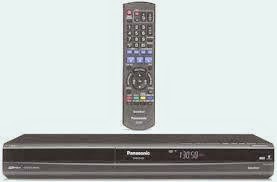
PANASONIC DMR-ES18GCA _ DVD Recorder - SMPS (Power Supply) SCHEMATIC

$
0
0
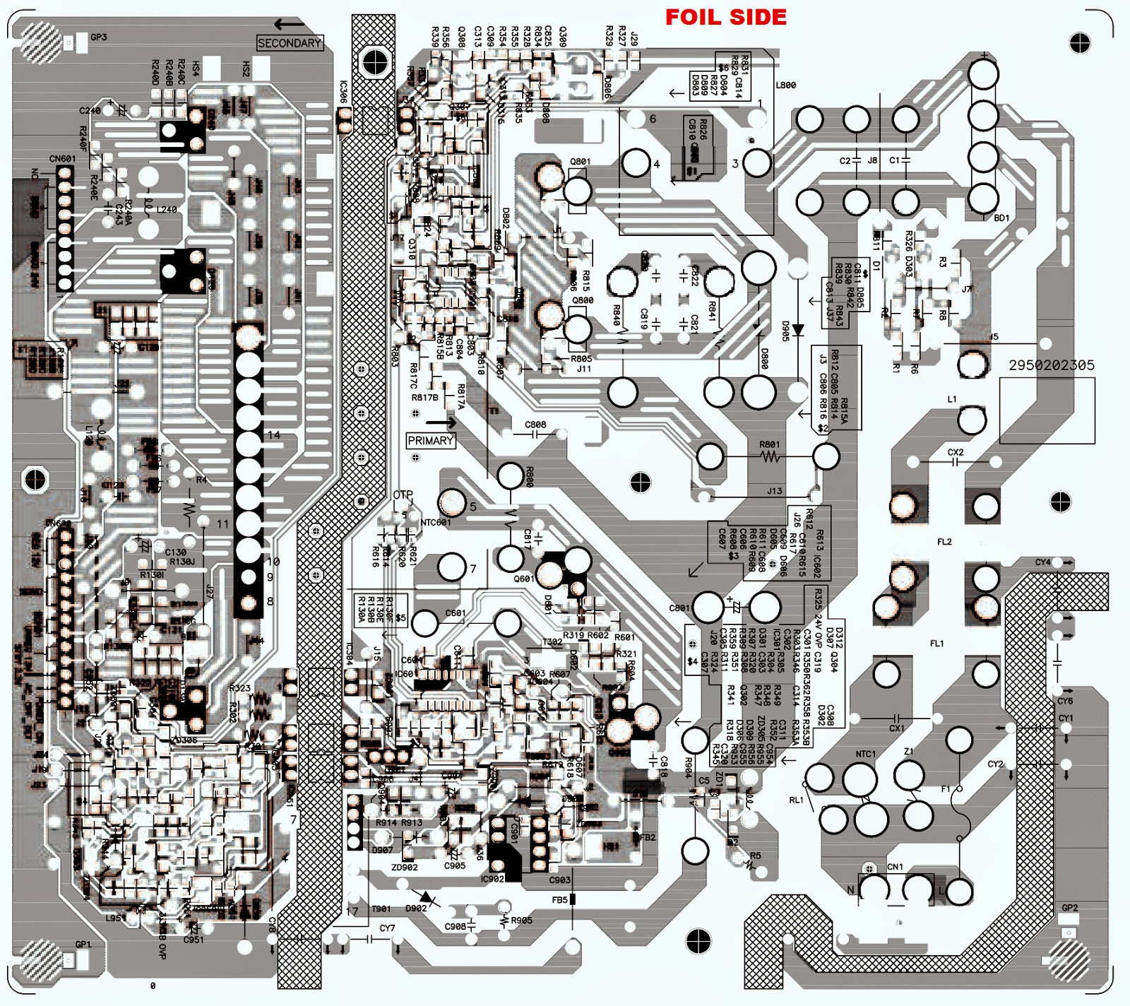
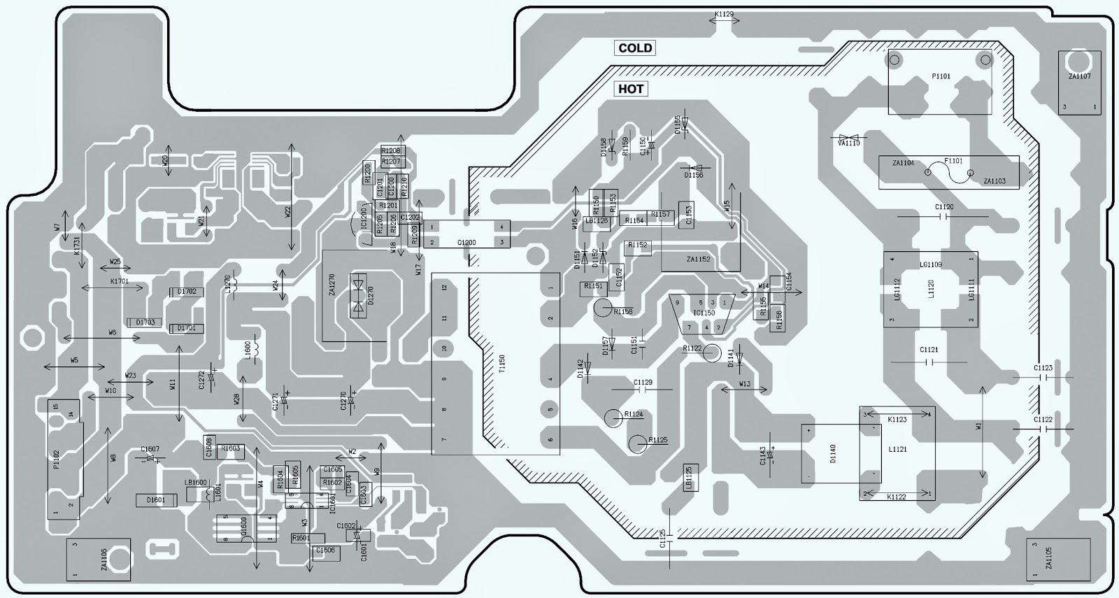
PANASONIC DMR-ES18EE - DMR-ES18GC - DMR-ES18GCS - DMR-ES18GCA _ DVD Recorder - POWER SUPPLY [SMPS] _ Circuit Diagram and PWB
SMPS PWB & SCHEMATIC
CLICK ON THE PICTURES TO MAGNIFY

HOW TO TAKE DISC OUT IN EMERGENCY - PANASONIC DMR-ES18GCS DMR-ES18GCA DVD Recorder

$
0
0
TO TAKE THE DISC OUT
Taking out the Disc from DVD-Drive Unit when the Disc cannot be ejected by OPEN/CLOSE button
* When the power can be turned off:  Turn off the power and press [STOP] [CH UP] keys on the front panel simultaneously for 5 seconds.
* When the power cannot be turned off:  Press [POWER] key on the front panel for over 10 seconds to turn off the power forcibly, and press [STOP] [CH UP] keys on the front panel simultaneously for 5 seconds.
When the Forcible Disc Eject cannot be done.
Caution:If you push strong and move the Slide Cam to counter direction of the arrow, the stopper will be bended and Slide Cam won’t stop at Stopper and will reach position for taking out Transverse Base.  And transverse base might fall down later.  Do not move Slide Cam in the counter direction of the arrow.  Moreover, the slide cam will be on irregular position against condition of the shipment; if the tray is pushed by the hand after manual tray ejection is done, the hold of transverse base becomes imperfect, and the danger of fall of transverse base increases.  Close the tray completely after manual tray ejection was done.  Especially finish CLOSE function of try by electricity when the product will be transported after inspection.
DMR-ES18EE / DMR-ES18GC / DMR-ES18GCS / DMR-ES18GCA
* Turn off the power and pull out AC cord.
** Remove the Top Case.
*** Put deck so that bottom can be seen.
**** Remove the sheet of the bottom side.
***** Slide SLIDE CAM by Eject Pin (JZS0484) or minus screw driver (small) in the direction of arrow to eject tray slightly.
****** Put deck upward, and push out Tray by Eject Pin (JZS0484) or minus screw driver (small).

Service Mode and Error Codes PANASONIC DMR-ES18EE DMR-ES18GC DMR-ES18GCS DMR-ES18GCA DVD Recorder

$
0
0
Caution:  Pairing of RAM Drive and DIGITAL PCB as RAM/Digital PCB Module, have to be replaced together.  If the either RAM drive or Digital PCB is changed, RAM Drive unit has to be re-aligned; because the alignment data for RAM Drive Unit is stored in the Digital PCB.
RAM/Digital PCB modules are:
> RFKNES18EE (EE)
> RFKNES18GC (GC)
> RFKNES18GCS (GCS)
> RFKNES18GCA (GCA)
ERROR DISPLAY & DETAILS
Self-Diagnosis Functions
* Self-Diagnosis Function provides information for errors to service personnel by “Self-Diagnosis Display” when any error has occurred.
* U**, H** and F** are stored in memory and held.
* You can check latest error code by transmitting [0] [1] of Remote Controller in Service Mode.  
Automatic Display on FL will be cancelled when the power is turned off or AC input is turned off during self-diagnosis display is ON.
Error Code
Diagnosis contents
Description
Monitor Display
Automatic FL display
U30
Remote control code error
Display appears when main unit and remote
controller codes are not matched.
No display
DVD   *
“*” is remote controller code of the main unit.
Display for 5 seconds
U59
Abnormal inner temperature
detected
Display appears when internal temperature of
deck reaches limit temperature.
The power is turned off forcibly.
For 30 minutes after this, all key entries are
disabled. (Fan motor operates at the highest speed for the first 5 minutes. For the
remaining 25 minutes, fan motor is also
stopped.) The event is saved in memory as well
No display
U59
“U59 is displayed for 30 minutes
U61
The unit is carrying out its
recovery process. [WITH NO DISC IN THE DISC TRAY]
The unit detected an error while recording or playing with no disc in the disc tray.  The unit is carrying out its recovery process.  This process restores the unit to normal operation.  The unit is not broken.  Wait until the message disappears
No display
U61
U88
The unit is carrying out its
Recovery process.
Same as above
No display
U88
U99
Hang up
Displayed when communication error has
occurred between Main microprocessor and
Timer microprocessor
No display
U99
H19
Inoperative fan motor.
When inoperative fan motor is detected after
powered on, the power is turned off
automatically.
The event is saved in memory
No display
No display
F00
No error information
Initial setting for error code in memory
(Error code Initialization is possible with error
code initialization and main unit initialization.)
No display
No display
F58
Drive hardware error
When drive unit error is detected, the event is
saved in memory
No display
No display
F34
Initialization error when main
microprocessor is started up
for program recording
When initialization error is detected after
starting up main microprocessor for program
recording, the power is turned off
automatically.
The event is saved in memory
No display
No display
UNSUPPORT
Unsupported disc error
*An unsupported format disc was played,
although the drive starts normally.
*The data format is not supported, although
the media type is supported.
*Exceptionally in case of the disc is dirty
“This disc is inoperatable”
UNSUP > PORT display for 5 seconds.
NO READ
Disc read error
*A disc is flawed or dirty.
*A poor quality failed to start.
*The track information could not be read
“Cannot read.
Please check the
disc.”
No READ
HARD ERR
DRIVE ERROR
THE DRIVE DETECTED A HARD ERROR
“DVD drive error.”
Display for 5 seconds HARD DRROR
SELF CHECK
Restoration operation
Since the power cord fell out during a power
failure or operation, it is under restoration
operation.
*It will OK, if a display disappears
automatically. If a display does not disappear,
there is the possibility that defective Digital
P.C.B. / RAM drive.
No display
SELF > CHECK
PLEASE
WAIT
Unit is in termination process
Unit is in termination process now.
“BYE” is displayed and power will be turned
off.
In case “Quick Start” of setup menu is ON, it
is displayed in restoration operation for AC
off
No display
PLEASE > WAIT
UNFORMAT
Unformatted disc error
You have inserted an unformatted DVD-RAM
or DVD-RW that is unformatted or recorded
on other equipment
Format > this disc is not formatted properly.  Format the disc in ‘DISC MANAGEMENT’
UNFOR > MAT
IR ERR
IR communication error
[IR ERR] is displayed when communication
between Timer microprocessor and IR microprocessor fails.
No display
IR ERR
No REC
Recording is impossible
[No REC] is displayed when recording is
impossible due to the defect, dirt or wound of media.
No display
No REC
SERVICE MODE
Service mode setting 
While the power is off, press REC, CH UP and OPEN / CLOSE simultaneously for five seconds.
CLICK ON THE TABLES TO ZOOM IN

PHILCO (PHILIPS) - PH32S86DG - POWER SCHEMATIC - LED LCD TV

$
0
0
SMPS SCHEMATIC
AUDIO AMP
CLICK ON THE SCHEMATICS TO MAGNIFY


PHILIPS HTS3548W - POWER SUPPLY SCHEMATIC (Circuit Diagram)

$
0
0
SMPS (1)_SCHEMATIC
POWER (2)_SCHEMATIC
DIGITAL POWER AMP
CLICK ON THE SCHEMATICS TO ZOOM IN

MCM-330 MICRO HI-FI SYSTEM - PHILIPS - CIRCUIT DIAGRAM

$
0
0
PHILIPS Micro Hi-Fi System_MCM330_ SCHEMATI
ICs USED: TDA8932B_PT2314_S3F84HA­_BU9543A_BA5826FP
AC power (power adaptor)
* Input: 100-240V~,50/60Hz, 1.5A Max.;Output: 18V 2.5A; 
* Brand name: Philips; Model: OH-1048B1802500U-VDE.
* Total output power 2 X10W RMS (with Living Sound off); 4 x 6W RMS (with Living Sound on)
* Speaker Driver 3.5”woofer+0.8” tweeter.
* Support disc CD-DA, CD-R, CD-RW,MP3-CD, WMA-CD
POWER AMP CIRCUIT
TONE CONTROL
CD
CLICK ON THE SCHEMATICS TO MAGNIFY

YORKVILLE XS800H - AMPLIFIER - SCEMATIC (Circuit Diagram)

$
0
0
POWER SUPPLY YORKVILLE HYBRID AMP - XS800H
PRE-AMP
POWER AMP

THOMSON 32WSC910 - SERVICE MODE and ADJUSTMENTS

$
0
0
How to enter Service Mode & Adjustments _ Thomson 32WSC910 - 32" Colour TV.
SERVICE MODE
To enter service menu; open the "OVERVIEW" menu (keep the menu item cursor on the “Exit” item) and press “ 1 9 2 3” 
SERVICE MENU
* Sw version
* Setup
* Geometry
* Video
* Sound
* Pip Service
* EEPROM Reset
Service Version : It shows software version.
Setup: It includes CRT, OSD, TXT,Tuner,Scart, No Signal adjustmens-options.
Geometry:All geometry adjustments can be done via this menu.
Video: Video adjustments (white point,Black level etc.)
Sound: This submenu includes sound adjustmens and options like Prescale values of FM,NICAM,Scart,LL’. Also tv systems can be chosen in this menu.
Pip Service :With this menu, Some Pip adjustments can be done. Pip frame color, frame width etc.
EEPROM Reset :This is used for reset the TV. All geometry, sound, setup, pip values are set the default values.
Setup Menu
* CRT Type
* Translucency
* TXT Language
* Main Tuner Selection
* Pip Tuner Selection
* Main Tuner AGC
* OSD Brightness
* TXT Brightness
* OSD Contrast
* TXT Contrast
* Scart3 Option
* SVHS Option
* No Signal Status.
CRT Type
Options: 16/9 Tube – 4/3 Tube_ This item is for tube type selection.
Translucency:Adjustments : 0 … 128 step._ This is related to OSD visibility. At 0, it is hardly visible, at 128 OSD is solid.
TXT Language
Options : East – West_This is Teletext language option.
Main Tuner Selection
Option : orega – samsung – philips – alps.  After replacing the main tuner with the new one listed above, this option must be set.
Pip Tuner Selection.
Option : orega – samsung – philips – alps. After replacing the pip tuner with the new one listed above, this option must be set.
Main Tuner AGC
Adjustment : -15 … 15. Default Tuner AGC value is “0” . (Pip AGC adjustment is in “Pip service” menu)
OSD Brightness : Adjustment : 0 … 255.  Default value is 50. Low values make the OSD dark.
TXT Brightness
Adjustment : 0 … 255.  Default value is 20. Low values make the Teletext dark.
OSD Contrast : Adjustment : 0 … 64.  Default value is 8. Low values make the OSD Black.
TXT Contrast : Adjustment : 0 … 64.  Default value is 7. Low values make the TXT Black.
Scart 3 Option
Option : on – off.  It should be off if the third scart is not available on the hardware.
SVHS Option
Option : on – dvd – dvd logo – off.  It configures the SVHS input. If DVD available on the hardware, then it can be set dvd. DVD logo option is for starting-up with DVD logo on the screen. If there is no SVHS input, it should be set to “off”.
No Signal Status
Option : on – off.  If this option set to off, TV never shuts down in case of no signal available. It should be use at the time of production. Default value is “on”
Geometry Menu
* V-Slope
* V-Position
* V-Amplitude
* V-S correction
* H-Blanking
* H-Shift
* EW- Width
* EW- Pin cushion
* EW- Trapezium
* EW- Upper Corner
* EW- Lower Corner
* H-Parallelogram
* H-Bow
* EW-EHT compensation.
* Restore Default.
This menu is for tube geometry adjustments.
Video Menu
*  G2 Alignment
* White Point R
*  White Point G
* White Point B
* Peak White Limiter
* Black Level Offset R
* Black Level Offset G
* Gain Pre-scale RGB
* Fast Blanking Delay
* Luma Chroma Delay
* Restore Default
* Brightness Offset.
G2 Alignment
To adjust G2, press left or right navigation key on the RC. There is a message box at the bottom of the screen. Increase or decrease the G2 until “G2 is OK.”
Message appear in the message box.
White Point R :
White Point G:
White Point B :
Adjustment : 0 … 63
Black Level Offset R
Black Level Offset G
Adjustment : 0 … 15.
These are for white balance adjustments. This adjustment is done automatically at the factory. If it is have to do with manually, these items can be used.
Peak White Limiter
Adjustment : 0 … 15.  It puts a limit for white points in dark scenes. Default value is “0”
Gain Pre-Scale RGB
Adjustment : -32 … 32.  It adjust the scart input RGB level. Default value is 0.
Fast Blanking Delay
Adjustment :-8 … 7.  Default value is “0”.
Luma Chroma Delay
Adjustment :-8 … 7.  Default value is “0”.
Restore Default : Reset values.
Brightness Offset : Adjustment : -5 … 5.  This is an offset value for OSD brightness. Default value is -2.
Sound Menu
* L/L’ AGC Adj.
* PreSclScart
* PreSclFM
* PreSclNICAM
* ResvSndTh
* PreSclMONO
* TR
* BG
* DK
* I
* MN
* Default System.
L/L’ AGC Adj.
Adjustment : 0 … 20.  Default value is 7. Adjust the L/L’ Agc level.
PreSclScart: Adjustment : -24 … 24.  This is for scart input sound level scale. Default value is “0”.
PreSclFM: Adjustment : -24 … 48.  Front End sound input level scaler. Default value is 19.
PreSclNICAM: Adjustment : -12 … 48.  Front End NICAM sound input level scaler.
Resv Snd Th Should be “0”
PreSclMONO: Adjustment : -24 … 24.  Front End MONO sound input level scaler. Default value is 5
TR: Option : on – off.  This is for Turkey. It should be “off” in Europe.
BG :
DK:
I :
MN :
Option : on – off
These are TV systems. If multi-system TV feature is available on the TV set, all systems should be “on” except “MN”. MN system never is “on”.
Default System: Option : BG – DK – I
Pip Service
* Frame Color
* Frame Width Vert.
* Frame Width Hor.
* Pip Tuner AGC.
This service is available if required hardware is mounted.
Frame Color : Option : 0 – 1 – 2 – 3 – 4 – 5 – 6 – 7.  [0 : Black, 1 : Red, 2: Green, 3: Blue 4: Yellow, 5: Dark Gray, 6: Light Gray, 7: White.]
Pip frame color can be chosen one of them above.
Frame Width Vert. : Option : 0 … 6.  Frame vertical thickness is getting thick from 0 to 6. Default value is 3.
Frame Width Hor. : Option : 0 … 4.  Frame Horizontal thickness is getting thick from 0 to 4. Default value is 3.
Pip Tuner AGC : Adjusts Pip tuner AGC value.
Warning: This is available if a Pip tuner mounted to the chassis. If any adjustment attempt without Pip tuner causes the software crash and restart the TV set.

POWER [SMPS]SCHEMATIC (Circuit Diagram)- THOMSON 32WSC910P

$
0
0
Power, Video Output, Audio Amplifier & Horizontal and Vertical scan output schematic (Circuit Diagram)
SMPS SCHEMATIC
VIDEO OUTPUT
AUDIO OUTPUT
HORIZONTAL & VERTICAL OUTPUT
CLICK ON THE SCHEMATICS TO ZOOM IN

Viewing all 2033 articles
Browse latest View live


<script src="https://jsc.adskeeper.com/r/s/rssing.com.1596347.js" async> </script>