Quantcast
Channel: Electro help
Viewing all 2033 articles
Browse latest View live

CTV KIT-HITACHI - SCHEMATIC (Circuit Diagram) - 87PS38 (System Control)_24C04(Memory)

$
0
0
Color TV Kit; Hitachi Circuit Diagram [21” PAL M/N-NTSC-M AV-2 IN]

 ICs used: 87PS38 (System Control)_24C04(Memory)_TB1238N(Deflection-Video IF-Chroma jungle)_TC9028F_4053_{ENV56D71C3 Tuner-Serial Data-Serial Clock type}_TDA168469(Power Control)
Universal Remote Control Set-up Codes for Hitachi TVs: 0014 0018 0020 0022 0033 0044 0049 0050 0074 0086 0099 0101 0102 0104 0107 0110 0119 0126 0127 0150 0152 0161 0162 0165 0166 0168 0171 0178 0182 0186 0203 0213 0218 0219 0231 0233 0238 0309 0379 0456 0475 0611 0613 0622 0631 0633 0636 0671 0795.
CIRCUIT DIAGRAM [SCHEMATIC] {CLICK ON THE SCHEMATIC TO MAGNIFY}


JBL HT PS300 SUB-WOOFER - TROUBLESHOOTING - SCHEMATIC DIAGRAM

$
0
0
JBL HT PS300 _ THX Powered Subwoofer_120V & 230V Versions IRF530_TIP141_TIP146_MJE350_TL071CP
SPECIFICATIONS
Amplifier Power RMS........200Watts
Drivers..................Dual 12" with polymer -laminated cones
Inputs ...................THX and normal line level, high level
Outputs..................High Level Unfiltered Crossover Frequency........50-120Hz Normal and (continuously adjustable) High Level Inputs
Frequency Response........25Hz - crossover point (Determined by crossover setting)
Height...................21¾”
Width...................21"
Depth...................21"
Weight..................67lbs
TROUBLE SHOOTING BEFORE OPENING
  Check connections, control settings, driver and other possible external problems. If there is Output, determine if all controls and Inputs function properly. Rotate Pots over full range while applying lateral and vertical oscillating forces to locate possible intermittent function. High Level Inputs should be tested individually both differentially (signal from "-" to "+" with normal output) and in common mode (signal from low level ground to both "+" and "-" shorted together, giving virtually no output). While passing a signal, corner drop the enclosure a few inches to expose possible intermittent problems. Check woofer for rubbing of voice coil or tears in cone or surround. Check cabinet for loose extraneous articles which may have been pushed into rear port. If LED(s) are flashing at about 0.5Hz, then one or more of the internal fuses are blown.
  Replacing power transistors: Clip all 3 leads near body of transistor. Remove screw and discard device (keep hardware and insulator).  Holding each lead in turn with needle nose pliers, gently heat and remove cut lead from hole in edge or PCB.  Clean insulator and seating area on back of panel. Coat both sides of insulator with silicon (white) thermal compound (unless silicone rubber pads are provided), position it centered on back of device with holes aligned. Insert leads into PCB then place pair over hole in panel; ensure hole in insulator is aligned. Insert screw from far side, pass shoulder bushing over screw and carefully seat shoulder in hole in tab, add flat washer, lock washer and nut (finger tight). Center insulator tighten screw first then solder all three leads in respective slots with full fillet, being careful not to bridge pads. Use ohmmeter to verify there is no short from tab of transistor to panel, or between pads.
Tests
  Connect negative lead of DVM to either negative output terminal near the center of the main PCB. Use an insulated probe for the positive lead to probe various test points. Take care not to short the probe to adjacent points on the circuit board. Alternately, unplug both output wires to woofer and connect to these points: darker colored output wire (blue or black) is negative. Position a switched “power bar” with the switch in a convenient location near the edge of the bench well away form the unit so that it can be reached safely to turn AC power ON and OFF to unit without risk of accidental contact with exposed areas of assembly.
With "bar" switch OFF, plug amplifier cord into this controlled "power bar".
Observing appropriate safety procedures, turn "bar" ON.
With DVM probe, test following voltages:
+V  +50VDC±10%
-V  -50VDC±10%
A+  +15VDC±10%
A- -15VDC±10%
If any of these is incorrect, switch OFF and investigate power supply.
If DC is OK, check:
Speaker "OUT" tab > 0VDC ±0.03V
collector tab of Q6 >25VDC (+V+2)
collector tab of Q5 >-25VDC (-V +2)
Troubleshoot power amplifier if not correct.
T  urn AC OFF. After 60 seconds connect oscilloscope ground probe to either negative output terminal near the center of the main PCB. Connect the positive scope probe to the OUT terminal on the smaller driver board.   Set the oscilloscope controls to 20V/div. (DC) and 50msec/div. No load is needed.
  Turn AC ON. Set oscillator for about 42Hz sine wave and raise output level. Observe output of amplifier rise with oscillator level until sine begins to compress without distortion symmetrically, at about 3 volts inside +V/-V levels.
If there is no output, carefully probe each IC amplifier output in signal flow sequence starting from the input, with scope at about 0.5V/div., until the location of signal loss is located.
TURN AC OFF. Wait 60 seconds. Repeat
Flip "Phase" switch and confirm no loss of main output. With about 10V output, sweep oscillator frequency to verify filter and EQ functions.
Raise "crossover" to "100Hz" and confirm change in LPF corner. Operation of "Phase Reversal switch" should be readily apparent in this mode.
TURN AC OFF. Wait 60 seconds.
In turn, repeat) for Left and Right high level inputs, both differentially (normal) and common mode (null output). Return to) then move connections to "output 2", then repeat.
  If output transistors or other major components of power amplifier are replaced, re-test the unit without load using the following procedure (DO NOT just reapply full AC source). There should be no signal input for this test.
  If a dual tracking, current-limited DC supply is available (preferable method), attach it to +V, -V and common (WITH AC CORD UNPLUGGED!). Set current limit to about 1A and slowly raise output voltage to±40V, monitoring output with DC scope (10V/div).  Initially, output should stay at about zero volts, then deviate a small amount (<10 volts) due to offsets and imbalances, and quickly return to zero. In normal start up with fast rising voltages, this doesn't occur.
  After the fault has been corrected, re-test unit with load resistor. Attach an 8 ohm 100 watt resistor to speaker wire pair (for channel under test); re-apply oscillator to Input. Turn unit ON and turn signal source up. Amplifier should deliver about 60W RMS at 8Ω(about 110W at 4Ω) from a stiff source of rated voltage at frequencies within its band pass. Turn input down and disconnect load. There should be no instability or ringing on any of the output waveforms, unloaded and loaded. If some is observed, check compensation and gain-setting components, by-pass caps and damping networks (especially those involving C15, C17 and C12).
  Tack a 100 ohm 1/4W resistor in the R185 location. Turn unit ON; apply input signal.  Measure the DC voltage on pin 8 of IC U11 with the amplifier operating. The voltage should be approx. -15 Volts, and the oscillator frequency on pin 1 about 93 Hz. Carefully short pins6&7andobserve the output shuts down within 2 seconds. Remove short and amplifier output should return. Turn OFF and remove R185 resistor to restore full 350 second delay.
  After repair, inspect for possible safety hazards, including loose hardware, missing lock washers, correct fuses and lead dress of primary wires (these must be held in position with cable ties so that they cannot touch secondary components). With ohmmeter, check that panel is connected to signal ground. Re-attach speaker wires (if removed) to satellite PCB’s, RED or YELLOW wires on OUT terminals; BLACK or BLUE connected to ground terminals on main PCB.
SCHEMATIC DIAGRAM
CLICK ON THE SCHEMATICS TO ZOOM IN

LG HTS HT305SU – SH35SU-S/W - SCHEMATIC (Circuit Diagram)

$
0
0
HT305SU – SH35SU-S/W - LG HOME THEATRE SYSTEM
{SSC6200_KTC3209_PS9850_TAS5342DDV_NJM4580}
POWER REGULATOR [SMPS]
PWM
AMPLIFIER

ALNICO HAM RADIO VHF BASE – DR 130 – SCHEMATIC & ADJUSTMENTS

$
0
0
DR 130 - ALNICO VHF BASE (HAM RADIO) _ SCHEMATIC & ADJUSTMENTS _ EXPLODED VIEW
ICs USEDM37410M6H_AT24C08_AK3241_BU4052BF TX10487M_M67781L(TE1) _ M67781L(TE2)_UPC1241H_M56760FP [MAIN UNIT TE1 & TE2]
 {T / E / EZ / EA / TA} _ TK10487M_S-AV17_UPC1241H_M56760FP
CPU UNIT
MAIN UNIT
EXPLODED VIEW
ADJUSTMENTS
SSG Mod:1KHz +/-3.5KHz/DEV
SP terminal is connected to 8ohm dummy load.
RX speaker output level is 50 to 100Mw
*1 or bond-centre of your radio version
*2 or bond lower limit of your radio version
*3 or bond upper limit of your radio version
*1 or bond-center of your radio version
*2 or bond lower limit of your radio version
*3 or bond upper limit of your radio version
If the logic boad EJ-21D or EJ21D exists, first pull out the logic board and re-connect W3,W4,W5, so that the radio comes back to conventional.
ADJUSTMENT POINTS

INFINITY PRIMUSHCSCH/230 HCS - SCHEMATIC (Circuit Diagram)

$
0
0
PRIMUSHCSBK/230 - PRIMUSHCSBE/230 - PRIMUSHCSCH/230 - INFINITY
   Do not operate your speakers or sub-woofer with the bass, treble and loudness controls set to full boost. This will place undue strain on your electronics and speakers and could damage them.  The volume control setting on your processor/preamp or receiver is not a specific indication of the overall loudness level of the speakers. The only important consideration is the loudness level at which the system can be played, regardless of where the volume control is set.  Always turn down the volume control setting on your processor/preamp or receiver when changing a cassette or CD, or switching inputs to AM or FM operation. Excessively loud transients (clicks or popping sounds) can damage the satellite speakers and possibly the sub-woofer.
SCHEMATIC
CLICK ON THE SCHEMATICS TO ZOOM IN

MCC-1 - INFINITY - Sub Amplifier: Sub 100 - SERVICE HELP

$
0
0
Modulus Home Cinema System:  Sub Amplifier: Sub 100 _ INFINITY - Repair Help
MCC-1_CENTRE DISASSEMBLE
* Remove the grille.
* Remove the (7) exposed rubber grille retainers; this can be accomplished by carefully pulling them out of their cavities with long-nosed pliers or similar tool.
* Remove the (7) Phillips screws that are now exposed.
* Four additional screws lie underneath the two front trim panels; these can be carefully removed by applying a blow dryer (high or maximum) or heat gun to the trim panels. Take care not to direct the gun directly at the woofer or tweeter; do not burn yourself after each panel has been heated –gloves are recommended. See illustration. If either trim panel is damaged upon removal, order: part# MODCTRPLATE-L–Left Trim Panel: part# MODCTRPLATE-R –Right Trim Panel.
* Remove the (4) additional Phillips screws that are now exposed.
* Carefully lift the front baffle, with drivers attached, off the cabinet.
Reassembly: Adhesive already in place, if encrusted on the front baffle, must be removed by scraping it off as it may prevent the trim panel from sitting flush on the front baffle. New adhesive must be added to reattach the trim panel.
MODULUS MS-1 SATELLITE
* Remove the grille.
* Remove the (4) exposed rubber grille retainers; this can be accomplished by carefully pulling them out of their cavities with long-nosed pliers or similar tool.
* Remove the (4) Phillips screws that are now exposed.
* Two additional screws lie underneath the front trim panel; this can be carefully removed by applying a blow dryer (high or maximum) or heat gun to the trim panel. Take care not to direct the gun directly at the woofer or tweeter; do not burn yourself after the panel has been heated –gloves are recommended. See illustration. If this trim panel is damaged upon removal, order: part# MODSATDECCHAR (Charcoal): part# MODSATDECPLAT (Platinum)
* Remove the (2) additional Phillips screws that are now exposed.
* Carefully lift the front baffle, with drivers attached, off the cabinet.
Reassembly: Adhesive already in place, if encrusted on the front baffle, must be removed by scraping it off as it may prevent the trim panel from sitting flush on the front baffle. New adhesive must be added to reattach the trim panel.
SCHEMATICS

OREUS HCS-INFINITY - DISASSEMBLEY - SCHEMATIC _(Circuit Diagram)

$
0
0
INFINITY OREUS - CIRCUIT DIAGRAM & DISASSEMBLE PROCEDURE
SPECS:
* Frequency Response: Satellite:  95 Hz – 22 Khz (±3dB)
* Recommended  Amplifier: 25 – 100 Watts.
* Sensitivity:  (2.83V @ 1 meter)_85 dB
* Crossover Frequency:  3,5 Khz, 12 dB/Octave
* LF Drive Unit: Dual 80 mm CMMD, magnetically shielded.
* Tweeter: 10 mm, magnetically shielded.
* Satellite, Dimensions (H x W x D):
* Shelf position:  362 x 120 x 106mm
* Wall position:  386 x 120 x 97mm
* Stand position:  811 x 200 x 170mm
Center, Dimensions (H x W x D):
*Shelf position:  122 x 350 x 106mm
* Wall position:  146 x 350 x 97mm
* Finish: Silver gray
* Weight (Unit):  2,5 kg
Oreus Subwoofer
* Drive Unit:  1 active 210 mm, 2 x 210 mm ABR.
* Amplifier Output: 100 Watts
* Crossover Frequency: Variable 50 - 150 Hz
* Dimensions (H x W x D): 367 x 251 x 445 mm
* Finish: Silver gray
* Weight (Unit): 15,9 kg.
DISASSEMBLY
CIRCUIT DIAGRAM
CLICK ON THE PICTURES TO MAGNIFY

HOW TO ENTER SERVICE MODE - TOSHIBA PROJECTION TELEVISIONS

$
0
0
Service Mode & Adjustments _ Toshiba Projection Televisions.
Applicable to Toshiba PTVs Models_ 46H84_51H84_57H84_46H84C_51H84C_57H84C
 
SERVICE MODE [Factory Mode]
* Press MUTE button twice on Remote Control.
* Press MUTE button again to keep pressing.
* While pressing the MUTE button, press MENU button on TV set.
(Service mode display)S
DISPLAYING THE ADJUSTMENT MENU
Press MENU button on TV.
KEY FUNCTION IN THE SERVICE MODE
The following key entry during display of adjustment menu provides special functions.
* Screen adjustment mode ON/OFF: TV (ANT)/VIDEO button (on TV)
* Selection of the adjustment items: Channel▲/ (on TV or Remote)
* Change of the data value: Volume▲/▼ (on TV or Remote)
* Adjustment menu mode ON/OFF: MENU button (on TV)
* Initialization of the memory (QA02): RECALL + Channel button on TV
* Initialization of the self diagnostic data: RECALL + Channel button on TV
> “RCUT” selection:  1 button
> “GCUT” selection:  2 button
> “BCUT” selection:  3 button
> “SCNT” selection:  4 button
> “COLC” selection:  5 button
> Convergence adj : 7 button 
> Self diagnostic display: 9 button.
SELECTING THE ADJUSTING ITEMS
* Every pressing of CHANNEL button in the service mode changes the adjustment items.  ( button for reverse order)
ADJUSTING THE DATA
* Pressing of VOLUME/button will change the value of data in the range from 00H to FFH. The variable range depends on the adjusting item.
EXIT FROM SERVICE MODE
Pressing POWER button to turn off the TV once.
INITIALIZATION OF MEMORY DATA OF QA02 {After replacing QA02, the following initialization is required.}
1. Enter the service mode, and then select any register item.
2. Press and hold the RECALL button on the Remote, then press the CHANNEL▲  button on the TV. The initialization of QA02 has been completed.
3. Check the picture carefully. If necessary, adjust any adjustment item above.  Perform “Programming Channel Memory” on the owner's manual.
CAUTION:Never attempt to initialize the data unless QA02 has been replaced.
SELF DIAGNOSTIC FUNCTION
* Press “9” button on Remote Control during display of adjustment menu in the service mode.  The diagnosis will begin to check if interface among IC’s are executed properly.
* During diagnosis, the following displays are shown.


TOSHIBA 46H84_51H84_57H84_46H84C_51H84C_57H84C - HOW TO ADJUST CONVERGENCE

$
0
0
Convergence Adjustment Details to Toshiba PTVs - 46H84_51H84_57H84_46H84C_51H84C_57H84C
CONVERGENCE ADJUSTMENTS
> Receive NTSC signal.
> Enter to the service mode. (Service Mode entry details; by previous post here)
RCUT
40H
* Press "7" button to enter the convergence adjusting mode, and the internal net pattern will be displayed.
* Then, press "9" button to display vertical stripes.
* Select the point and the colour by pressing following buttons. (Cursor should be blinking.)
"2", "8", "4", "6" : To select point. 
3" : To select colour.
* Then press "5" button, and adjust the convergence by pressing following buttons. (Cursor should not be blinking.)
"2", "8", "4", "6" : To adjust convergence.
"3" : To select colour.
* Repeat from steps 3 to 4 until the convergence and the geometry become fine.
* Press "7" button to memorize the adjusted data.
> Message of "PLEASE PUSH TOUCH FOCUS" will be displayed, and press TOUCH FOCUS button which is located on the front panel.
> TOUCH FOCUS CALIBRATION will start.
> Soon message of "CALIBRATION FINISHED" will be displayed, and then a normal picture will be displayed.
> Push TOUCH FOCUS button again, and confirm that the convergence does not change.
> If message of "TOUCH FOCUS ERROR" is displayed, check the connection between four sensors and Convergence Unit.
> Check the geometry of internal net pattern.
> If any problem cannot be found, hardware might have problem.
EXPLANATION OF KEY-FUNCTION IN THE CONVERGENCE ADJUSTMENT MODE
Load BACK UP DATA
1 button
Up :
2 button
Select Green color
3 button
Left
4 button
Blinking of cursor ON/OFF
5 button
Right
6 button
Adjust mode ON/OFF
7 button
Down
8 button
Vertical stripe ON/OFF
9 button
Erase Green line
0 button
Erase Red line
100 button
Erase Blue line
ENT button
The following message will appear while pressing "1" button.
* ENTER: TO LOAD BACKUP DATA
* MUTE: TO LOAD INITIAL DATA
* EXIT: TO EXIT
  BACKUP DATA sets in factory by performing CALIBRATION. BACKUP DATA updates by performing CALIBRATION again. INITIAL DATA uses the seed data on this model. Thus, it cannot updates. INITIAL DATA is not adjusted. Therefore, convergence data operates incorrectly. Normally, BACKUP DATA operates as base data on this model. If BACKUP DATA is incorrectly operated, INITIAL DATA is operated instead of BACKUP DATA In many cases, colour mis-convergence may be corrected by returning HIT and WID data in main deflection side to initial adjusting values. Following cases will surely require readjustment of convergence.
Convergence_46_51_57 Wide.
Focus adjustment
(Condition)
* User Adjustment : SPORTS (CONTRAST MAX, BRIGHTNESS CENTRE)
* Adjust after Cantering Magnet adjusts
* Signal : Lens Focus : R Dot cross (NTSC)
G Dot cross (NTSC)
B Dot cross (NTSC)
Electrical Focus : R Dot cross (NTSC)
G Dot cross (NTSC)
B Dot cross (NTSC)
Adjustment
1. Common Items
1) Rough Adjust the lens focus and electrical focus of each color(R, G, B)
2.Green Adjustment
1) Receive green single colour by shielding jig.
2) Receive the Dot Cross pattern.
3) Adjust Green electrical focus.
Adjust Green electrical focus VR on focus pack (Z410) for best centre focus.  If the focus blur on screen centre and circumference, adjust the electrical focus is best point on all of screen.
4) Adjust Green lens focus.
Receive the Dot Cross pattern. Adjust Green lens for best centre focus.
Green lens focus adjustment target
Dot-cross has red flare (red flare width :1mm)
5) Repeat (3)~(4),and adjust best focus point.
Red Adjustment
1) Receive Red single colour by shielding jig.
2) Receive the Dot Cross pattern.
3) Adjust Red electrical focus.
Adjust Red electrical focus VR on focus pack (Z410) for best centre focus.
4) Adjust Red lens focus.  Receive the Dot Cross pattern. Adjust Red lens for best centre focus.
5) Repeat (3)~(4),and adjust best focus point.
Blue Adjustment
1) Receive Blue single colour by shielding jig.
2) Receive the Dot Cross pattern.
3) Adjust Blue electrical focus.
Adjust Blue electrical focus VR on focus pack (Z410) for best centre focus.  (The Brightness is minimum point of Blue.)
Adjust Blue lens focus.
> Receive the Dot Cross pattern. Adjust the Blue lens for best centre focus.
> After easy lens adjustment, turn to right side lens focus screw, and so dot-cross has flare.
> Next turn left focus screw, so flare disappears in Dot-Cross and Dot-Cross become blur.
> This point is blue lens focus adjustment target. (Flare disappears and become blur)
CRT REPLACEMENT
When CRT is replaced, main deflection readjustment and colour matching are required.
Perform following procedures.
1. Replace two CRT’s of blue and red.
2. Perform horizontal adjustment for blue and red yokes on base of green CRT data. Mount yoke and velocity mod. coil alignment, pushing towards CRT without gap.
3. Adjust alignment of blue and red. (Refer Alignment adjustment for details.)
4. Rotating entering magnet, adjust CRT centres of red and blue to CRT centre of green. (Picture position adjustment)
5. Adjust HIT and WID data of main deflection, and decide data at the most precise screen comparing to green data.
6. Adjust convergence of screen picture for colour matching. Do not move green one at this time.
7. After convergence adjustment of screen picture finishes, replace green CRT.
For green CRT as well, repeat steps 2 to 5 above on bases of red and blue colour matching to adjust convergence.
8. Execute TOUCH FOCUS following instructions displayed on the screen after finishing convergence adjustments of all the colours.
Note: Press button "7" again after "PLEASE PUSH TOUCH FOCUS" has been displayed. Then, TOUCH FOCUS will not be executed, and the current state of convergence will be displayed.

HOW TO ENTER SERVICE MODE - JVC LT-20J50SJ, LT-20J50SU - LCD PANEL TELEVISION

$
0
0
Universal Remote Control Set-up Codes for JVC brand TVs [With different brand remote controls]
0007 0018 0075 0103 0123 0154 0163 0170 0182 0214 0225 0409 0433 0465 0657 0670.
TO ENTER THE UOCIII SERVICE MODE
1. Press [MENU] key.
2. Press the [4], [7], [2] and [5] key, and UOCIII SERVICE MODE screen will be displayed.
HOW TO EXIT THE UOCIII SERVICE MODE
Press [MENU] key to exit the UOCIII SERVICE MODE.
CHANGE AND MEMORY  SETTING VALUE
SELECTION OF SETTING MENU & ITEM_ ([P +/-]key.)
CHANGE OF SETTING VALUE (DATA)_ ([Volume +/-]key.)
MEMORY OF SETTING VALUE (DATA)
The setting value will be stored automaticallywhen release the REMOTE CONTROL UNIT keys.
SELECTION OF SETTING MENU & ITEM _  [FUNCTION ▲  /▼ ] and [FUNCTION ◄ / ► key.
„CHANGE OF SETTING VALUE (DATA) _  [FUNCTION ◄/►KEY]
HOW TO ENTER THE PW SERVICE MODE
Press [INFORMATION]key and  [MUTING]key simultaneously, and PW SERVICE MODE screen will be displayed.
HOW TO EXIT THE PW SERVICE MODE
Press [MENU] key to exit the PW SERVICE MODE.
CHANGE AND MEMORY SETTING VALUE
MEMORY OF SETTING VALUE (DATA)
{In case of Service Sub-menu 1 and Service Sub-menu 2}
The setting value will be stored automatically when release the REMOTE CONTROL UNIT keys.
{In case of Factory Settings 1 and Factory Settings 2}
1. Press [MENU] key.
2.  Press the [4], [7], [2]and [9]key to store the setting value.
3.  After storing the setting value, the message "Factory Settings OK" will be displayed.
PW SERVICE MODE SETTING ITEMS
LCD PANEL
  This unit uses the flat type panel LCD (Liquid Crystal Display) panel that occupies as little space as possible, instead of the conventional CRT (Cathode Ray Tube), as a display unit. Since the unit has the two polarizing filter that are at right angles to each other, the unit adopts "normally black" mode, where light does not pass through the polarizing filter and the screen isblack when no voltage is applied to the liquid crystals.
PIXEL FAULT
  There are three pixel faults - bright fault , dark fault and flicker fault - that are respectively defined as follows.
BRIGHT FAULT
  In this pixel fault, a cell that should not light originally is lighting on and off.  For checking this pixel fault, input ALL BLACK SCREEN and find out the cell that is lighting on and off.
DARK FAULT
  In this pixel fault, a cell that should light originally is not lighting or lighting with the brightness twice as brighter as originally lighting.  For checking this pixel fault, input 100% of each R/G/B color and find out the cell that is not lighting.
FLICKER FAULT
  In the pixel fault, a cell that should light originally or not light originally is flashing on and off.  For checking this pixel fault, input ALL BLACK SCREEN signal or 100% of each RGB color and find out the cell that is flashing on and off.

SYLVANIA LC200SL - LC370SS8 - 20”&37" COLOR LCD TV - SERVICE MODE- POWER SUPPLY REGULATOR SCHEMATIC

$
0
0
Service Mode_Initialization_Initial Setting Values_Power Supply Regulator section Schematic & Universal Remote Control Set-up Codes. SYLVANIA LC200SL8 – 20” COLOR LCD TV
Universal Remote Control Set-up code list.
3-digit codes:  004,008,009,062,068,069,074, 075,077,155,161,163,189,198
4-digit codes0001 0321 0371 0701 0931 0961 1021 1221 1381 1801 1821 2761 1961 2321 0392
5-digit codes20675, 20821, 21268.
SERVICE MODE 
* Use the service remote control unit.
* Turn the power on. (Use main power on the TV unit.)
* Press the service button on the service remote control unit.
PREPARING A SERVICE REMOTE CONTROL OUT OF SUPPLIED REMOTE CONTROL ALONG WITH TV
Cut “A” portion of the attached remote control unit as shown.
INITIAL SETTING VALUES [DEFAULT DATA VALUES]
Enter the Service mode.  Set the each initial data as shown on table.
HOW TO INITIALIZE (Reset) THE TV
* Turn the power on. (Use main power on the TV unit.)
* To enter the service mode, press the service button on the service remote control unit.
>> To cancel the service mode, press [POWER] button on the remote control.
* To initialize the LCD television, press [DISPLAY] button on the remote control unit.
* Confirm "FF" indication on the upper right of the screen.
POWER SUPPLY REGULATOR SECTION CIRCUIT.
Fixed Voltage (or Auto voltage selectable) power supply circuit is used in this unit.  If Main Fuse (F601) is blown, first check to see that all components in the power supply circuit are not defective before you connect the AC plug to the AC power supply. Otherwise it may cause some components in the power supply circuit to fail.
CLICK ON THE SCHEMATIC TO ZOOM IN

JBL GT BASSPRO II Sub-Woofer - WIRING DIAGRAM - CIRCUIT DIAGRAM (Car Audio) [LM3700 IC]

$
0
0
JBL BASSPRO II_SCHEMATIC & WIRING DIAGRAM - Used IC-LM3700 _ Exploded View

SPECIFICATIONS
Amplifier power: 100 Watts
Frequency response: 20Hz – 120Hz
Fuse rating: 20A
Max current draw: 12A
Idle current draw: <800mA
Input sensitivity: 50mV to 4V Line-level input; 1V to 16V universal interface
Crossover frequency: 70Hz – 120Hz
Crossover slope: 12dB
Dimensions (L x W x H): 16-1/8" x 9-1/2" x 12-1/4" (includes mounting feet) (410mm x 242mmx 312mm)
WIRING DIAGRAM
  When using the high-level input connections, BassProII will automatically turn on when you turn on your radio.  In this case, the remote (REM) connection is not needed. Use at least #20 AWG speaker wire for speaker-level input connections.
  Use at least #12 AWG wire for the Positive Battery (BATT +12) and Ground ( ) connections. If needed, use at least #20 AWG wire for the remote (REM) turn-on connection.  Connect BassPro II’s “BATT +12V” terminal directly to the battery’s positive (+) terminal. Install a fuse holder, with a 20A fuse, within 18" of the battery’s positive (+) terminal.  Route all power wires through a grommet in the vehicle’s firewall. If a factory grommet is not available, install one.  Connect a short ground wire from
  Bass Pro II’s ground terminal GND to the nearest bare metal surface. For a good connection, use sandpaper to clear paint from the metal surface and use a screw with a lock (star) washer.  The remote (REM) connection requires a +5 to +12 Vdc signal for Bass Pro II to turn on when using the line-level connections. Most head units with preamp outputs provide this remote voltage signal. As an alternative, connect this terminal to a switched ignition circuit.
SCHEMATICS
EXPLODED
PWB
CLICK ON THE PICTURES TO MAGNIFY

BRITANIA BS140 - RADIO_TAPE_CD Combo - SCHEMATIC (Circuit Diagram)

$
0
0
BRITANIA BS140 – BS140N – BS190N – BS192 – BS192N – RADIO_TAPE_CD Combo.
{LA1824_KA2206B/KT2206B/SJ2206_MM1469_A2282_LA9251M_LC78602HKE_LA6541D_LC78602R-8616_LA9242_LA6541D}
SCHEMATIC                       {Click on the Schematics to Zoom in}

OKI Data - MB460_470_480 - PRINTER - CLEANING PROCEDURE

$
0
0
Cleaning of LED lens array_ paper path in the ADF_ INSIDE OF THE MFP_ PAPER FEEDING ROLLER AND PAD_ LED HEAD
The following parts should be replaced at a specified cycle.
The above mentioned regular parts exchange should be done by users.
* Toner Cartridge > After printing approx. 3,500 pages > LED head
* Image Drum Cartridge > After printing approx. 25,000 pages.
[After using a normal cartridge, the starter toner cartridge (attached at the printer purchase) can not be used. Use the starter toner cartridge fist, and then, use the normal toner after [LOW TONER] is displayed]
Cleaning
Remove toner powder and dust in the printer inner section. Clean the inside of and the periphery of the printer with the cloth as needed. Clean the printer inner section with the handy cleaner.
[Do not touch the image drum, LED lens array, and LED head terminal.]
CLEANING PAGE FUNCTION
The printer has the charging roller cleaning function implemented by the user.
The following shows the procedure in the printer operation panel.
1. From the panel menu , Select the [Menu] - [Printer Menu] - [Printer Adjust] - [Cleaning] - [Execute] .
2
. Feed a piece of A4 paper in the multi-purpose tray or the manual feeder slot.
3.
Press the "start" Button. (In case of MB470/MB480 )
4.
The toner attached with the image drum is transferred on the paper fed, and paper is fed under the condition where the remaining toner is printed. While this processing is in progress, LCD shows the [Print Cleaning Page] message is displayed.
5.
The display on LCD is returned to [Function].
Cleaning of LED lens array
If the vertical white lines, and white belt (white spot, pale printing) occur in printing, the LED lens array should be cleaned or the toner cartridge should be replaced.
CLEANING LED HEAD
If there appear line breaks or white lines, or the letters and characters are blurred, please clean your LED head.
* Switch off the power supply.
* Lift the scanner. The
* Press OPEN button and open the top cover. [fuser unit is extremely hot. Do not touch it.]
* Lightly wipe the lens (4 points) of the LED head with soft tissues. [Do not use solvents as methyl alcohol or thinner, as they might cause damage to the LED head.]
* Close the top cover.
* Lower the scanner.
Cleaning the pick-up roller
If there appear vertical lines on the printing side, please clean the pick-up roller. [In order not to cause damage to the surface of roller, please use soft cloths to clean it.]
CLEANING PAPER FEEDING ROLLER AND PAD
* Draw out the paper cassette.
* Get the cloths wet and wring it out. Then use the cloths to wipe paper feeding roller (large)and paper feeding roller (small).
* Get the cloths wet and wring it out. Then use the cloths to wipe the pad part of paper cassette.
CLEANING THE INSIDE OF THE MFP
* Switch off the power supply.
* Lift the scanner.
* Press OPEN button and open the top cover. [The fuser unit is extremely hot. Do not touch it.]
* Take out the image drum cartridge. { Take out the image drum cartridge and put them on a flat surface.  Cover the image drum cartridge with black paper.  The image drum (the green cylinder) is very easy to be damaged, please be careful when handling it.  Don’t put the image drum cartridges in direct sunlight or strong light (above1500 lux).  And don’t put them in indoor lighting condition for more than 5 minutes}
* Get the cloths wet and wring it out. Then use the cloths to wipe any paper dust of the Guide-Paper-R.
* Gently put the image drum cartridge back into your MFP.
* Close the top cover.
* Lower the scanner.
Cleaning the paper path in the ADF{ When dirt is found on an image read by the ADF.}
* Turn off the power of MFP.
* Open the ADF Top cover
* Pinch the ADF lock lever and turn the Kernel Assy up until it is locked
* Using a soft cloth, remove dirt with a sweeping action to the direction of the arrow. [Do not use benzene, thinner and alcohol.]
* Get back the Kernel Assy to the initial position.
* Close the ADF Top Cover.
Cleaning the underside of the ADF[When dirt is found on an image read by the ADF]
* Open the ADF Doc Lid.
* Wipe the A part (transparent) to remove dirt with a soft cloth. [Do not use benzene, thinner and alcohol.]
* Close the ADF Doc Lid.
CLICK ON THE PICTURES TO MAGNIFY

HOW TO DISASSEMBLE OKI B460_MB470_MB480

$
0
0
Disassemble Roller-Pick-Up, Roller-Feed-Now; Guard-Connector, Connector(9715S-08Z02-G4C); Roller-Feed
* Remove Cassette-Assy.
* Push the claw in the direction of the arrow to remove Roller-Pick-Up (1) .
* Push the claw in the direction of the arrow to remove Roller-Feed-NOW (2) .
* As for reinstalling, take the opposite sequence to removal sequence.
> When reinstalling Roller-Pick-Up (1) , push it until it clicks.
> When installing Roller-Feed-Now (2) , push it until it clicks.
Guard-Connector, Connector (9715S-08Z02-G4C)
* Turn off the printer and pull the AC cord. Remove the printer from the device.
* Remove two Screw-Shoulders (1).
* Remove the connector (2) to remove Guard-Connector(3) , Connector (9715S-08Z02-G4C)(4) 
As for reinstalling, take the opposite sequence to removal sequence.
Roller-Feed
* Turn off the printer and pull the AC cord. Remove the printer from the device.
* Remove the 4 screws (Black) (1) , Remove the clamp of claw at the 2 places and remove CoverFront (2) .
* Slide the left side of Shaft-Roller-Feed (3) to the front, and remove three Roller-Feeds (4).


SONY KV 29FV15B_KV32FV15B_KV38FV15B - Power Supply Regulator & Horizontal and System Control Schematic

$
0
0
Power Supply Regulator_System Control and Horizontal Scan Output Circuit [Schematic] - SONY KV 29FV15B_KV32FV15B_KV38FV15B
UPC339C_MCR5102_ON3171R (OPTO-COUPLER)_CXA2135S_CXP85858A-024Q- [Micon] & M24C08 [Memory]
Four Digit Set-up codes with universal remote control for Sony TVs: 0018 0045 0101 0131 0154 0177 0211 0301 0302 0357 0358 0609 0785 

POWER SUPPLY REGULATOR SCHEMATIC [Clcik on the schematics to Magnify]
HORIZONTAL SCAN_SYSTEM CONTROL
T503 Line Output Transformer part numbers:
KV29FV15B – 8-598-834-20
KV34FV15B – 8-598-824-10
KV38FV15B – 8-598-824-10

POLYVOX CP-750D - SCHEMATIC [Circuit Diagram]

$
0
0
CIRCUIT DIAGRAM (Schematic) _ POLYVOX CP-750D
SCHEMATIC[Click on the schematic to Magnify]

SONY LCD TVs - T"Con BOARD FAULTS and TROUBLESHOOTING

$
0
0
TROUBLESHOOTING T'CON BOARD _ LCD PANEL _ SONY LCD TVs
  A typical LCD panel and the associated video processing circuits as found in the WAX3 chassis. The various formats and resolutions of video signals are processed on the BU1 board. All video signals exit the video processor in the native resolution of the LCD panel.  In this design, the resolution is for a 1366 by 768 at 60HZ refresh rate panel. 48 horizontal lines are discarded to match up to the 720p resolution of the ATSC specifications so the video will exit as 720p.  The LCD panel used in this model processes 8-bit RGB video data. Before the video information can be sent to the TCON board it must be converted to a format that allows for practical and noise-free transmission. The large number of parallel lines to transmit the 8-bit RGB data would need to be sent on differential lines for noise reduction. This would require 48 lines just for the video. The TCON circuit also requires B+, ground connections, a communications bus, sync, and a clocking line transmitted differentially so we can see that up to 60 lines would be required for an 8-bit video signal and significantly more lines for a 10-bit processor. The practical way to transmit this information is to convert the parallel video data to a serial stream and this is accomplished by the Low-Voltage Differential Signaling (LVDS) transmitter. 
  The LVDS transmitter contains a circuit to serialize the parallel data. The parallel video information along with sync and clocking data are transmitted via twisted line pairs. Depending on the logic level, current is sent along one or the other of the twisted pair of wires. The receiving end of the wires is loaded with a resistor (usually around 100 to 120 ohms). The receiver detects the polarity of the voltage drop across the resistor to determine the logic level. The current level swings in the wire are about 3ma with a voltage differential of around 350mv. This allows for transmission of the video signal with minimal EMI.  The LVDS receiver on the TCON board converts the serialized data back to parallel. This data is processed by the timing control IC to allocate the RGB data into serial streams for processing by the LCD panel. The  TCON transmits the pixel control data to the panel via flat, flexible circuit board cables which can number 2 or 4 depending on the bit rate and refresh timing of the panel. A 1366 X 768 panel requires about 180 lines to transmit control information and B+ from the TCON. This number of control lines is not even close to the number of horizontal or vertical rows of pixels so the LCD panel must use this information to further expand the ability to turn on each individual crystal. The process will be explained in the gate and source driver paragraphs.  All of this is accomplished by the TCON board. The term “TCON” is short for Timing Control. Other LCD panel manufacturers may have a different  name for this particular circuit but the term used by Sony will always be TCON.
Gate Drivers
  The IC’s located along the side of the panel.  These IC’s are mounted on a flexible cable(s) which are bonded to the LCD panel. Their function is to activate each row of pixels one at a time starting with the first line at the top. As each line is activated, the source drivers turn on the appropriate liquid crystals for the frame of video about to be displayed. This continues from top to bottom until the entire frame of video is displayed. The process is repeated for the next frame. This rate can vary from 60 times per second or be increased to 120 or 240 as found in the high-frame-rate panels. 
Source Drivers
  These IC’s provide the control voltages to turn on each RGB segment of the vertical rows of pixels. In this example, the panel has a horizontal resolution of 1366 pixels. Each pixel is made up of a red, green and blue liquid crystal which means there are 4,098 columns to control.  The source drive IC’s contain shift registers along with buffer switches. Shift registers are used to convert serial data to parallel. By using this method, the TCON is able to transmit control information to each of the source drivers using serial data lines. If the TCON is transmitting 8-bit data to the panel, each data line is capable of controlling 256 lines exiting the source drivers. Understanding how the gate and source drivers work together makes it easier to observe a problem on the screen and determine if the failure is panel or TCON related.
Diagnosing a Failed TCON
  In order for this concept to move forward successfully, it is important that the service industry be able to properly identify the symptoms of TCON issues to avoid unnecessary service calls and repair costs. Accurate analysis of TCON failures will reduce costs significantly (both in parts costs and time) when warranty repairs are involved and will reduce the number of COD repairs that are lost.  A good approach when determining a TCON failure is a good understanding of which symptoms ARE NOT caused by the TCON. Examples are as follows:
Video Process Failures
  All video inputs received by the video process circuits are handled on a frame-by-frame basis. The video frames are converted and scaled to 8 or 10-bit RGB information. It is virtually impossible for the video process circuits to cause a problem on a specific area of the screen. Failures on this board usually appear as distortions, colour level shifts, video level shifts, noise that involves the entire picture, or no picture at all. The TCON can generate symptoms that appear to be video process related but the video process circuits cannot produce the symptoms of a failed TCON circuit. 
LVDS Cable Failures: 
  Although problems with the LVDS cable or connectors can generate symptoms of TCON failures this usually tends to be intermittent and wiggling of the connectors will usually provoke a change in the symptom on the screen. LVDS cables and connectors have become rather robust over the past few years and most problems are caused by technicians who damage them and this is generally quite obvious upon close examination.
LCD Panel Failures
  Some LCD panel failures could possibly be mistaken for TCON issues. Other than damage to the LCD glass, most panel failures are isolated to a particular area of the screen. Since the TCON disperses the pixel data to groups of line and column drive IC’s situated on the outer edges of the panel, it is unlikely that more than one of these IC’s would fail at the same time. Multiple columns of stuck on or stuck off pixels are, therefore, more likely to be the fault of the TCON circuits. The same applies to a single row of lit or unlit pixels. The TCON simply cannot cut out a single line of information.
Failures involving the LCD panel are usually displayed with the following symptoms:
* Physical damage such as cracks in the panel, a single pixel or group of pixels that always on or off, or random sections of the panel which are completely dark.
* Source driver failure. This symptom appears as a single vertical band around 1 to 2 inches (depending on the panel size) and can be black, white, or any other colour. It can also contain video information with distortion. A single vertical line that is dark or coloured. This may be due to a tab bonding failure from the IC to the panel but either cause requires the replacement of the panel.
* Gate driver failure. These IC’s operate in a “bucket brigade” fashion. As mentioned earlier, the gates drivers scan each horizontal line starting at the top. If any one of the gate drivers fails, all of the subsequent drivers below it will fail to operate properly. This symptom is usually indicated by normal video on the upper portion of the screen followed by distorted video from the point of the failed IC and downward.
* Any horizontal lines. The gate drivers are activated by a single source of timing information so any single horizontal line or groups or random horizontal lines are caused by an output failure from a gate driver or a loss of the tab bond to the panel.
TCON Failures
  Failures in the timing control circuits of the TCON can produce symptoms of absolutely no video or generate lines and patterns that usually cover all or a substantial part of the screen. Determining if the TCON is the cause of a “no video” condition is a bit more difficult since there are no indications on the screen to analyse.
Troubleshooting a “DEAD” TCON
  Many of the Sony television models over the last few years will detect a TCON that has completely failed. The communications data between the video process circuits and the TCON will cease to communicate if the TCON fails completely. This will cause the television to shut down and display a diagnostics code indicating a failure of the TCON. Not all chassis designs have this feature and it is not found on older models.  The typical scenario when this failure arises is for the technician to bring a video process board to the repair location. It is usually safe to assume that the problem lies on the TCON board if the replacement video board does not remedy the problem since it is highly unlikely that a replacement board with the same failure was received.  One trick to check most TCONS for functionality is to loosen the LVDS connector at the TCON (as shown In Figure 4-3) while the unit is turned on. Handle the LVDS connector with care and be certain to fully release the lock tabs. Gently rock the cable in and out of the connector while observing the screen for any response. Depending on the chassis, the symptoms of the screen may be gentle white flashes, intermittent coloured lines, or a screen full of random patterns. The idea at this point is to provoke some kind of response on the screen. TCON boards that have failed will not usually generate any type of response on the screen.  Another helpful procedure is to rapidly heat and/or cool the TCON with hot air devices or circuit coolant and watch for patterns to appear on the screen.
  Figure illustrates 2 examples of a loss of control data to the drive IC’s. In the first example, an entire group of column drivers has lost the data stream for red. The second example involves the complete loss of drive data for all RGB information to the right side of the screen. This is sometimes caused by the flat cable connecting the TCON to the LCD panel coming loose. The area of missing video can be dark or completely white depending on the panel design.
Service Tip: Select an inactive input (or one that is known to be a 4:3 SD source) and toggle between the “normal” and “zoom” modes. If the lines follow the zoom changes, the problem is located on the video process board. If they stay in the same place, they are originating in the TCON or LCD panel.
Actual TCON Failures
  The illustrations show other TCON failures that have been encountered in the field. The idea is to get a grasp of the concept of TCON induced failures to avoid unnecessary parts replacement.
LCD Panel Failures
  Below are some photos of actual LCD panel failures. Note that most issues tend to be isolated to a certain area of the screen with the exception of failures of the source drivers. The source drivers can cause thin horizontal line issues and can also affect a large area of the screen.

CLICK ON THE PICTURES TO ZOOM IN

AKAI LCT 2016-LCD TV POWER SUPPLY [SMPS] SCHEMATIC and V-VHIP PASSWORD RESET PROCEDURE

$
0
0
POWER SUPPLY [SMPS] SCHEMATIC and V-VHIP PASSWORD RESET PROCEDURE _ Universal Remote Control Set-up Codes_AKAI LCT2016 LCD TV
V-Chip Reset_If you did forget the Password.
Omnipotence V-Chip Password: 3308.
* Press MENU button.
* Press MENU buttons to highlight "CCD\V-CHIP" Menu.
* Press Up, Down buttons to highlight "SET V-CHIP".
* Press Up, Down buttons to highlight "
CHANGE PASSWORD".
* Use the Number buttons (0~9) to enter an omnipotence Password.
* Press MENU button to confirm and your can select "CHANGE PASSWORD".
Suggest
: Change to your familiar Password again.
Universal remote control set-up codes to check with Akai TVs
0049 0050 0055 0066 0076 0102 0107 0110 0123 0141 0150 0039 0101 0152 0182 0195 0209 0225 0379 0428 0433 0437 0119 0166 0181 0214 0222 0231 0235 0247 0460 0465 0601 0611 0618 0622 0631 0633 0638 0649 0655 0669 0672 0673 0734 0792 0810 0813
  If your set need a 3 digit code, enter these codes, by eliminating the leading "0" from each code.  That's, for a code "0049", you can make it as "049" and for "0813" as "813" and so.
SMPS Schematic (Circuit Diagram)
CLICK ON THE SCHEMATIC TO ZOOM IN

SHARP 21V-FL200 - CRT TV - SERVICE MODE - CIRCUIT DIAGRAM (Schematic)

$
0
0
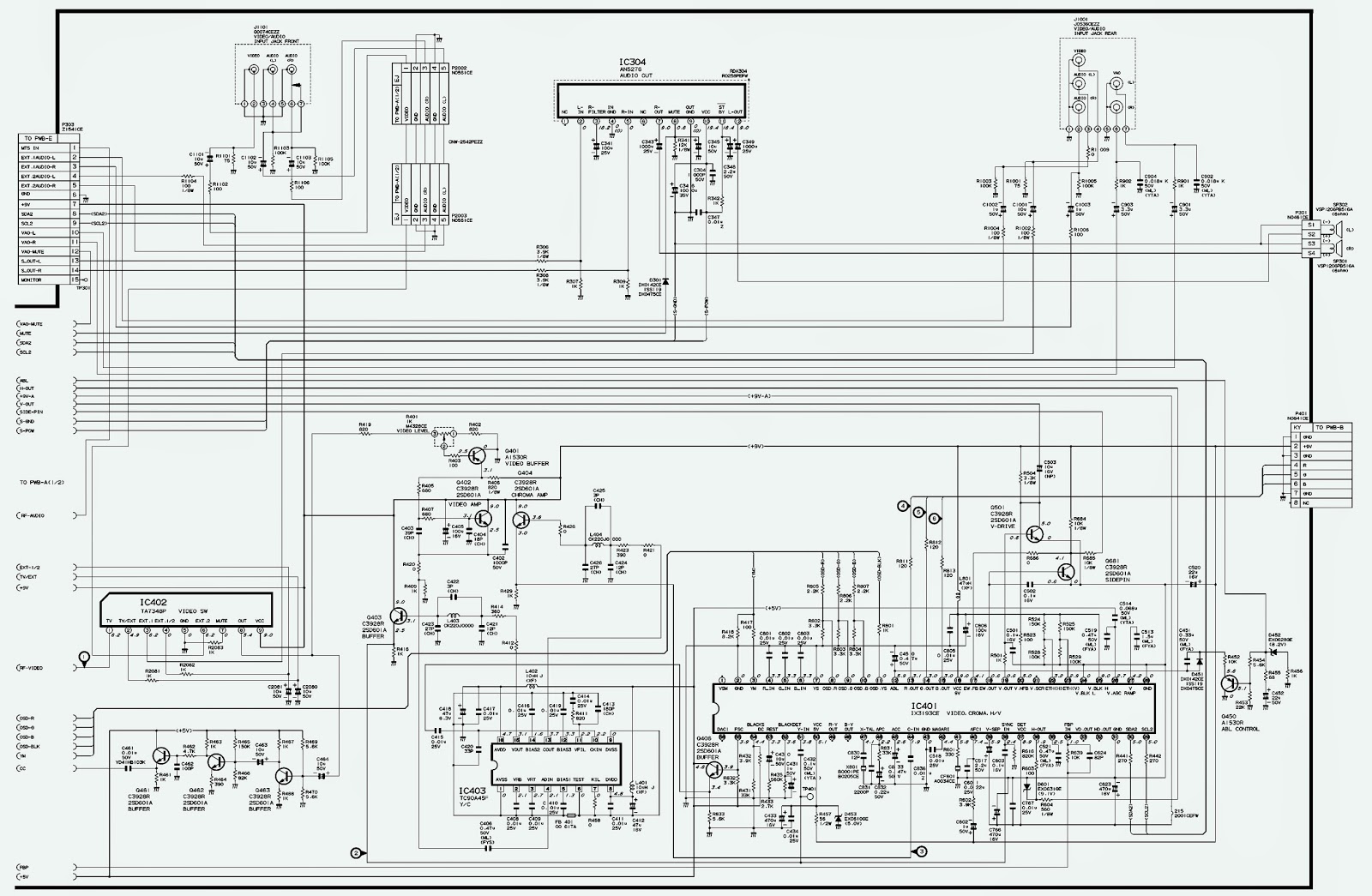
Service Mode – Circuit Diagram - Universal remote control set-up code list. Sharp 21VFL200
USED ICs: M24C02B_LA7841_IX3466CE_CXA2074Q (MTS)_AN5276 (Audio Output)_TA7348P_IX3193CE (Video-Chroma)
SERVICE MODE
  Before putting unit into the service mode, check that customer adjustments are in the normal mode. Use the reset function in the video adjustment menu to ensure customer controls are in their proper (reset) position.
Once in the service mode, press the Ch-up or Ch down button on the remote controller or at the set.
The service adjustment number will vary in increments of one, from "S01" to "I05".
Select the item you wish to adjust.
To enter the service mode and exit service mode.
* While pressing the Vol-Up and Ch-Up buttons at the same time, plug the AC cord into a wall socket.
* Now the TV set is switched on and enters the service mode.
* To exit the service mode, turn the television off by pressing the power button.
UNIVERSAL REMOTE CONTROL SET-UP CODE LIST FOR SHARP TVs
0007 0018 0044 0094 0154 0170 0190 0308 0320 0362 0631 0675
CIRCUIT DIAGRAM [Click on the Schematics to Zoom In]

Viewing all 2033 articles
Browse latest View live


<script src="https://jsc.adskeeper.com/r/s/rssing.com.1596347.js" async> </script>