Quantcast
Channel: Electro help
Viewing all 2033 articles
Browse latest View live

Lenovo Idea Tab A2107A Hardware Maintenance - How to replace the FRU – Disassemble procedure

$
0
0
Any computer part containing transistors or integrated circuits (ICs) should be considered sensitive to electrostatic discharge (ESD). ESD damage can occur when there is a difference in charge between objects. Protect against ESD damage by equalizing the charge so that the machine, the part, the work mat, and the person handling the part are all at the same charge.
Before the computer is powered on after FRU replacement, make sure all screws, springs, and other small parts are in place and are not left loose inside the computer. Verify this by shaking the computer and listening for rattling sounds. Metallic parts or metal flakes can cause electrical shorts.
The battery pack contains small amounts of nickel. Do not disassemble it, throw it into fire or water, or short-circuit it. Dispose of the battery pack as required by local ordinances or regulations. Use only the battery in the appropriate parts listing when replacing the battery pack. Use of an incorrect battery can result in ignition or explosion of the battery.
[Some models of Lenovo computer are equipped from the factory with an optical storage device such as a CD-ROM drive or a DVD-ROM drive. Such devices are also sold separately as options. If one of these drives is installed, it is certified in the U.S. to conform to the requirements of the Department of Health and Human Services 21 Code of Federal Regulations.]
Before replacing parts:
Make sure that all software fixes, drivers, and BIOS downloads are installed before replacing any FRUs.
After a system board is replaced, ensure that the latest BIOS is loaded to the system board before completing the service action.
To download software fixes, drivers, and BIOS, follow the steps below:
1. Go to http://consumersupport.lenovo.com/.
2. Enter a serial number or select a product or use Lenovo smart downloading.
3. Select the BIOS/Driver/Applications and download.
4. Follow the directions on the screen and install the necessary software.
If you replaced an FRU, but the replacement does not solve the problem, reinstall the original FRU before you continue.
• Some computers have both a processor board and a system board. If you are instructed to replace either of them, and replacing one of them does not solve the problem, reinstall that board, and then replace the other one.
• If an adapter or a device consists of more than one FRU, any of the FRUs may be the cause of the error. Before replacing the adapter or device, remove the FRUs one by one to see if the symptoms change. Replace only the FRU that changed the symptoms.
Attention: The setup configuration on the computer you are servicing may have been customized. Running Automatic Configuration may alter the settings. Note the current configuration settings (using the View Configuration option); then, when service has been completed, verify that those settings remain in effect.
• Before replacing any FRU, read the entire page on removing and replacing FRUs.
• When you replace FRUs, use new nylon-coated screws.
• Be extremely careful during such write operations as copying, saving, or formatting. Drives in the computer that you are servicing sequence might have been altered. If you select an incorrect drive, data or programs might be overwritten.
• Replace an FRU only with another FRU of the correct model. When you replace an FRU, make sure that the machine model and the FRU part number are correct..
• An FRU should not be replaced just because of a single, irrepairable  failure. Single failures can occur for a variety of reasons that have nothing to do with a hardware defect, such as cosmic radiation, electrostatic discharge, or software errors. Consider replacing an FRU only when a problem recurs. If you suspect that an FRU is defective, clear the error logs and run the test again. If the error does not recur, do not replace the FRU.
• Be careful not to replace a non-defective FRU.
Removing and replacing the FRU
1.Do not attempt to service any computer unless you have been trained and certified. An untrained person runs the risk of damaging parts.
2. Before replacing any FRU, review “FRU replacement notices”.
3. Begin by removing any FRUs that have to be removed before the failing FRU.
4. Follow the correct sequence in the steps to remove the FRU, as given in the figures by the numbers in square callouts.
5. When turning a screw to replace an FRU, turn it in the direction as given by the arrow in the figure.
6. When removing the FRU, move it in the direction as given by the arrow in the figure.
7. To put the new FRU in place, reverse the removal procedures and follow any of the notes that pertain to replacement.
8. When replacing an FRU, use the correct screw
After replacing an FRU, do not turn on the computer until you have made sure that all screws, springs, and other small parts are in place and none are loose inside the computer. Verify this by shaking the computer gently and listening for rattling sounds. Metallic parts or metal flakes can cause electrical short circuits.
The system board is sensitive to, and can be damaged by, electrostatic discharge. Before touching it, establish personal grounding by touching a ground point with one hand or using an electrostatic discharge (ESD) strap (P/N 6405959) to remove potential shock reasons.
SIM card cover and battery pack removal
Push the SIM card cover forward with two thumbs in the direction shown by arrow
Remove screw [1] and push the battery pack backward in the direction shown by arrow.
Base cover removal
Remove 16 screws on the base cover with the screw driver
Remove the base cover in the direction shown by arrow
Disconnect the battery connector , insert a flat blade under the bottom right of the battery and carefully pry out the battery in the direction as shown.
Remove the Micro SD card from the card slot in the direction shown by arrows
When handling the system board,
• Be careful not to drop the system board on a bench top that has a hard surface, such as metal, wood, or composite.
• Avoid rough handling of any kind.
• In the whole process, make sure not to drop or stack the system board.
• If you put a system board down, make sure to put it only on a padded surface such as an ESD mat or conductive corrugated material.
Peel off the microphone , vibrator , speakers , detach the LCD connector , touch connector , USB board connector , back camera connector , power button board connector ,volume up/down button connector.
Remove the system board in the direction shown by arrow
Removal steps of back camera
The back camera is stuck to the system board. Remove the back camera from the system board in the direction shown by arrow.
Overall disassemble procedure


Sharp 27US100, 27US60 – how to enter the service mode, adjustments circuit diagram

$
0
0
Used ICs: IX3354CE, IX3528CE, LA7841, TEA1507(power switching control) STP7NB60(SMPS switch), F0049ME or FA004WJ (Fly-back transformer) - Sharp 27U-S60, Sharp 27U-S100. 
The receiver is protected by a 4.0A fuse (F701), mounted on PWB-A, wired into one side of the AC line input.

For adjustments of this model, the bus data is converted to various analog signals by the D/A converter circuit.  There are still a few analog adjustments in this series such as focus and master screen voltage. Follow the steps below whenever the service adjustment is required.
To enter and exit service mode.
Before putting unit into the service mode, check that customer adjustments are in the normal mode. Use the reset function in the video adjustment menu to ensure customer controls are in their proper (reset) position.
While pressing the Vol-up and Ch-up buttons at the same time, plug the AC cord into a wall socket.  Now, the TV set is switched on and enters the service mode.
To exit the service mode, turn the television off by pressing the power button.
In the service mode, you will see the window screen as window 1. There are 4 adjustment categories 2 DEF, 3 SIGNAL, 4 FEATURE, 5 FIX VALUE as shown below:
Press CH UP/DOWN button for selection and enter by VOL UP or VOL DOWN.
Press CH UP/DOWN button to select the adjustment item and VOL UP/DOWN to adjust the data number for each categories.
(OSD disturbance can be erased by R/C display key) (Note: EEPROM - factory used only)
Service mode windows
CRT base card circuit diagram [Schematic]
Main board schematic
Click on the schematics to magnify
Service mode adjustments detail
+B Adjustment
[All DC voltages are measured with DVM connected between points indicated and chassis ground, line voltage set at 120V AC and all controls set for normal picture unless otherwise indicated.]
1. Receive a good local channel.
2. Select VIDEO ADJUSTMENT RESET on the menu to get the video reset.
3. Connect a DC voltmeter between the +B line (at SW transformer) of R611 and the ground terminal.
4. Make sure that the voltmeter reads 128.5±1.5V
Video Level (TV Det Video Level) Adjustment
1. Receive a good local channel.
2. Enter the service mode signal category and select the service adjustment "S02".
3. Set the data value to "02" first, and then adjust the data to "04". (If out of spec, readjust the data in the range of "00" to "07" to obtain a normal contrast level.)
RF AGC Adjustment
1. Receive a good local channel.
2. Enter the service mode signal category and select the service adjustment "S01".
3. Set the data value to point where no noise or beat appears.
4. Select another channel to confirm that no noise or beat appears.
Note: You have to exit the service mode first to select another channel.
Screen Adjustment
1. Connect to oscilloscope probe between TP854 and ground of the CRT unit.
2. Receive a good local channel.
3. Enter the service mode Signal category and set the service adjustment "S04" to step 30. Then select the service adjustment "S12" and set the data value to "00" to set the color level to the minimum level. (record the original data first). You may skip this step, if you selected a B/W picture or monoscope pattern. Set also the "S05/S06/S07" data to minimum level ("00").
4. Select the service adjustment "S03" and set the data value to "01" to turn off the luminance signal (Y-mute).
5. Select the service adjustment "S14" and adjust the data value to obtain 2.35 volts.
6. Adjust the master screen control until the raster darkens to the point where raster is barely seen.
7. Adjust the service adjustment "S05" red, "S06" green, "S07" blue to obtain a good grey scale with normal white at low brightness level.
8. Select the service a adjustment "S03" and reset data to "00". Select the service adjustment "S12" and reset data to obtain normal color level.
9. Remove probe and reset the master screen control to obtain normal brightness range.
White Balance Adjustment
1. Receive a good local channel.
2. Select the service adjustment "S12" and set the data value to "00" to set the color level to the minimun. You may skip this step, if you selected a B/W picture or monoscope.
3. Alternately adjust the service adjustment data of "S08" and "S09" until a good grey scale with normal white is obtained.
4. Select the service adjustment "S12" and reset data to obtain normal color level.
Sub-Picture Adjustment
1. Receive a good local channel.
2. Make sure the customer picture control is set to maximum.
3. Enter the service mode and select the service adjustment "S10".
4. Adjust the data value to achieve normal contrast range.
Sub-Tint Adjustment
1. Receive a good local channel.
2. Set the customer tint control to the center of it’s range.
3. Enter the service mode and select the service adjustment "S11".
4. Adjust "S11" data value to obtain normal fresh tones.
Sub-Color Adjustment
1. Receive a good local channel.
2. Make sure the customer color control is set to center position.
3. Enter the service mode and select the service adjustment "S12".
4. Adjust "S12" data value to obtain normal color level.
Sub-Brightness Adjustment
1. Receive a good local channel.
2. Make sure the customer brightness control is set to center position.
3. Enter the service mode and select the service adjustment "S13".
4. Adjust "S13" data value to obtain normal brightness level.
Vertical-Size, V-Linearity and V-S Correction Adjustments
1. Receive a good local channel.
2. Enter the service mode DEF category and select the adjustment "D02" for Vertical Size, "D05" for VLinearity and "D06" for V-S Correction Adjustment.
3. Set in order "D05" for V-Linearity, "D06" for V-S Correction and set the data to get the best linearity.
4. Then adjust "D02" data until it become a proper vertical size.
Horizontal Position Adjustment
1. Receive a good local channel.
2. Enter the service mode DEF category and select the adjustment "D01".
3. Adjust "D01" data value to center the picture.
Vertical-Phase Adjustment
1. Receive a good local channel.
2. Enter the service mode DEF category and select the adjustment "D03".
3. Adjust "D03" bus data to get the most acceptable vertical position.
Note: The step range is 20 (32)+12 (3 steps)/ -20 (5 steps).
(Push once move 4 steps.)
Caption Position Adjustment (Horizontal)
1. Receive a good local channel.
2. Enter the service mode DEF category and select the adjustment "D04".
3. A black text box will appear on the screen.
4. Adjust "D04" data value to balance the text box position in the center. (A=B).
MTS ADJUSTMENT
MTS Level Adjustment
1. Feed the following monaural signal to pin (14) of IC3001.  Monaural signal: 300Hz, 245mVrms
2. Connect the rms voltmeter to pin (39) of IC3001.
3. Enter the service mode and select the service adjustment "M01".
4. Adjust the data so that the rms voltmeter reads 490 ±10mVrms.
MTS VCO Adjustment
1. Keep the unit in no-signal state.
2. Connect the frequency counter to pin (39) of IC3001.
3. Connect a capacitor (100µF, 50V) in between positive(+) side of C3005 and ground.
4. Enter the service mode and select the service adjustment "M02"
5. Adjust the data so that the frequency counter reads 62.94 ±0.75kHz.
Filter Adjustment
1. Feed the following stereo pilot signal to pin (14) of IC3001.
Stereo pilot signal: 9.4kHz, 600mVrms.
2. Enter the service mode and select the service adjustment "M03".
3. Adjust the data at the point where "OK" appears on the screen. The "OK" represents the approximate center of the adjustable range of the data.
Separation Adjustment
1. Connect the rms voltmeter to pin (39) of IC3001.
2. Receive the following composite stereo signal 1.
Composite stereo signal: 30% modulation, left channel only, noise reduction on, 300Hz
3. Enter the service mode and select the service adjustment "M04".
4. Adjust the data until the AC voltage reading of the rms voltmeter is minimum.
5. Receive the following composite stereo signal 2.
Stereo signal: 30% modulation, left channel only, noise reduction on, 3kHz
6. Enter the service mode and select the service adjustment "M05".
7. Adjust the data until the AC voltage reading of the rms voltmeter is minimum.
8. Take the above steps 1 thru 7 again for fine adjustment.

TCL 32D2930 LED LCD TV – how to enter the service mode, service adjustment details

$
0
0
TCL 32D2930/MT56E1-LA - LED LCDTV -service mode, factory mode, software update, white balance adjustment and other service adjustment details.
When replacement parts are required, be sure the service technician has used replacement parts specified by the manufacturer that have the same characteristics as the original part. Unauthorized substitutions may result in fire, electric shock, or other hazards.
MT56-AP chassis are designed for Asia & Pacific (AP) market Ready for Smart TV. It features by its high integration, easy debugging (ADC adjustment free) as well as convenience in terms of maintenance. Fast software upgrade through USB disk facilitates both manufacture and after-sale service.
Factory Main Menu (FMM) is divided into Factory menu and Design menu. Factory Menu covers all indispensable functions during manufacture such as White Balance Adjustment, SHOP etc., while Design Menu includes Service Menu, Hotel Menu, Param Setting, Other Setting etc. Some settings like Param Setting and Other Setting is exclusively used by R&D engineer, anyone else shouldn’t change the settings in the menu. When you wish to learn the product information like project ID, project name, Hardware, software version, releases date, you can access to Service Menu.
The main chip is from REALTEK
Factory Menu: Accessing Way
a. When the Factory hotkey item of Factory Menu is disabled (OFF), press Menu button of remote control, then select Settings/Picture, make sure the cursor stop on Contrast item submenu. Finally, press 9, 7, 3, 5 consecutively.
b. When the Factory hotkey item of Factory Menu is enabled (ON, you can see the flashing Factory Captions Info on the lower left corner), press Back button of remote control.
Press RCU “OK” key to enter the submenu.
Press RCU “Right” or “Left” key to change the values.
Press RCU “Right” or “Left” key run the function.
Press RCU “Back” or “Menu” key exit the Factory menu.
While “FactoryKey” is enabled, there is some toggled display information relative to MV, SV, ID, MID, to facilitate 100% quick screening without accessing to whatever else menu
Design Menu
Design Menu includes Factory Menu, other, Service Menu, Param Setting, Hotel Menu.
Some settings like Param Setting and Other Menu is exclusively used by R&D engineer, anyone else shouldn’t change the settings in the menu. When you wish to learn the product information like project ID, project name, chassis name, software version, release date, you can access to Service Menu. In addition, in Hotel
Menu, we also provide a great deal of useful functions for specific applications in hotel.
Accessing 
a. When the Design mode hotkey item is disabled(OFF), press Menu button of remote control, then select Settings/ Picture, make sure the cursor stop on Contrast item submenu, press 1, 9, 5, 0 consecutively.
b. When the Design mode hotkey item of Design Menu is enabled (ON, you can see the flashing Factory Captions Info on the lower left corner), press Back button of remote control.
* Press RCU OK key to enter the submenu.
* Press RCU Right/Left key to change the values.
* Press RCU Right/Left key run the function.
* Press RCU Back/Menu key exit the Factory menu.
Design Captions Information is the same to Factory Captions Info.
Other Menu
The Other Menu contains some TV basic information, with which we can check the TV setting before production.
Service Menu
Service Menu contains some basic information of the device, such as Project ID, Hardware, Software version, USB Update etc. This menu is especially useful for after-sale service.
Param Setting Menu
Param Setting menu contains Sound Setting, Picture Curve, Picture Setting, SSC, DBC, CI Card, Overscan, WIFI CHECK and USB FILE. But it is exclusively used by R&D engineer, anyone else shouldn’t change the settings in the menu.
Pre-Conditions and Power Supply Check
Before power-on, please check the board according to the relevant block diagram and circuit diagram, make sure that no serious issue or mistake can destroy the board. For example, the output of DC/DC and LDO should not be shorted to ground.
Supply a suited voltage and power-on, then check the voltage according to the relevant block diagram, circuit diagram and voltage spec, the error should be less than 5%, for example, the voltage for main chip (+3V3, +2.5V, VDDC1V15, 1V5_DDR, etc.), the voltage for TUNER (TU_3V3), the voltage for amplifier (AMP_VCC), etc.
Project ID Modification
There are different ID stored in the EMMC depending on different Panels settings and Model features, but there’s only one key branching Project ID able to ensure normal display. And when you power on the TV set, you should make sure the Project ID is accord with the BOM description. If not, you need to modify the ID. There are two methods to modify the ID:
Change Project ID in Design Menu
In case of “Design mode hotkey” is enabled, press “Back” button to enter Design Menu. To modify Project ID, you need to go through “Service menuàProject ID”, then press Left or Right key to select suitable ID (Project name is dynamically refreshed). Finally restart the TV set.
In case of “Design mode hotkey” is unabled, you can enter the Design Menu easily with reference to 3.1 Design Menu.
Change Project ID with Remote control unit
Press “062598”+”Menu”+”XXX” (XXX represents project ID you’d like to switch to) in the remote control and wait about half minutes, When the set restart automatically, you have successfully changed project ID
below is none exhaustive ProjectID table for reference
Function Test
Once the Project ID is correct and the TV display normally, plug all external generator devices to relevant inputs/outputs below according to their respective test patterns format and check picture content and sound quality accordingly.
LAN/WLAN Test
MAC Address Upgrade
Upgrading MAC address needs to use the tool in factory and through serial command. The specific method is according to the operation of the factory guidance.
Device ID (DID) and User ID (UID)
Purpose is to allow Other Network Download (OND) and further specific services over dedicated portal based on AP. For such, specific DID (32 bytes) and UID (8 bytes) needs to be paired and overwritten into memory for internal client encryption, as below.
Those DID/UID codes can only be set using UART commands following enclosed SIACP requirements.
LAN Test
A rough LAN test can be done by connecting Ethernet to TV’s RJ45 and check that IP, subnet mask, DNS addresses, which are visible on Home
àSettingsàNetworkàEthernet settingsàIP settings” (ensure that “Internet Connection” is Enabled at first). More in-depth test can be performed faster using suitable UART/IR commands following SIACP requirements. SW will internally manage Network ID (NID) flag controlling all MAC/DID/UID integrity to facilitate PA screening further.
SHOP INIT
At final process stage, it’s necessary to perform Shop init before any packing to leave Factory mode and restore User default presets according to the requirement of order.
This function is accessible by selecting“Factory Menu
àShop”, then pressing RCU “Right ”or” Left” key.
Warm-up Test
It’s required minimum 15min of Warm-Up that can be considered as Burn-In. Additional aging for White Balance alignment is no more necessary due to consistent picture
performance with cloning usage. This function is accessible by selecting “Factory menu Warm up”, pressing RCU “Right” or ”Left” key to set it ON, and then it enter in Warm up mode. Press “Menu” key on keyboard to exit the burning mode.
Software Upgrade: How to upgrade Mboot
Connect the computer and main board VGA port by a serial port tool.
Serial connector definition: VGA/P303: Pin4: RXD VGA Pin11:TXD
Open MTK “Mboot” software programming tool “Flash Tool”, and set serial port.
Import the mboot file,
power on the TV, then Click Upgrade key and you will see the below message
How to upgrade FLASH Software
USB Upgrade
Download the update file (generally named V8-MT56551-LF1VXXX.pkg) to the root directory of your USB device, and make sure there’s no other bin file named analogously. Then insert the USB device to USB interface of TV set.
Power on the TV set, Press and hold on the menu key of key board at the same time. If the TV is updating, you’ll see the upgrade screen.
Upgrade process takes about 3~5 minutes.
After updating, the TV set will reset automatically.
Online Upgrade
Download the bin zip file “V8-MT56551-LF1VXXX.Zip” to the root directory of your USB device, and do not change the file name. Then insert the USB device to USB interface of TV set.
Press RCU Menu/Settings/Picture/Contrast/1,9,5,0/Service menu/USB Update /Main Upgrade/Local Update . If the upgrade file is found, TV will give a message that it verifying. TV displays a warning message, it means selecting “confirm” to continue or “cancel” to exit. During updating, do not power off the TV set.
After updating, the TV set will reset automatically.
Network Connection
You can set up your TV so that it can access the Internet through your local area network (LAN) using a wired or wireless connection.
Connect to a wired network
Attach the TV set to your LAN using cable in three ways:
Connecting the LAN port on the TV to an external modem using a Cat 5 cable
Connecting the LAN port on the TV to an IP Sharer which is connected to an external modem. Use Cat 5 cable for the connection.
Depending on how your network is configured, you may be able to attach the TV to your LAN by connecting the LAN port on your TV directly to a network wall outlet using a network cable. Note that the wall outlet is attached to a modem or router anywhere in your house.
Select Home→ Settings→ Network → Ethernet Settings→IP Settings, then the TV will obtain IP address Automatic configuration. In addition, you can set the IP address and password manually.
Connecting to a wireless network
To connect the TV set to your network wirelessly, you need a wireless router or modem and a Wireless LAN Adapter.
If the TV set is equiped with an internal WiFi module, select Home→ Settings→ Network→ Wireless Settings, then turn on Wireless Switch, select a wireless network and press OK to connect.
If you want to connect the TV set to a wireless network by a Wireless High Gain USB Adapter (USB dongle), select Home→ Settings→ Network→ Wireless Settings, then turn on Wireless Switch and External WiFi, and select a wireless network and press OK to connect.
White Balance (WB) Adjustment
The White Balance generally is customized by PQ engineer, and uploaded to the PDM system, anyone else shouldn’t change the value in the menu. If it is necessary to adjust, the following content can offer some reference, but the process of adjusting White Balance is out of the range of this file. Refer to the relevant technical file of HuiZhou factory of TCL
Calibration of Color Temperature
According to TCL standards, the color temperature and white reference coordinates of LCD like the following table: (This standard is based on CA-310 color temperature meter)
White balance adjustment takes the Normal color temperature of HDMI channel as the reference
Warm and Cold tone is relative to Normal mode. The adjustable gain range is 0~255
The Normal color temperature of other channel is relative to the Normal mode of HDMI channel. The adjustable gain range is also 0~255
The manual adjustment is according to the regulation above. Additionally, when manually adjust, it needs to do White Balance in it first.
Take signal generator 22293 as an example, the timing value and pattern value of each source show in the following table.
Click on the pictures to magnify

LG CM6520 (CM6520, CMS6520F/W) – How to disassemble the CD changer mechanism - Mini Hi-Fi System

$
0
0
Compact disc players incorporate a great many ICs as well as the pick-up (laser diode). These components are sensitive to, and easily affected by, static electricity. If such static electricity is high voltage, components can be damaged, and for that reason components should be handled with care.

DISASSEMBLY AND ASSEMBLY FOR MECHANISM DECK (CDM-H1803)
* Disassemble the Cover Guide Disc.

* Disassemble the Loading FFC from the Main PCB Assy.
Turn the Gear in OPEN direction as shown in Figure to take out the Tray Loading Assy in 3 direction.
* Pull up the Holder 1 to completely disassemble the Tray Loading Assy from the Base Main Assy
* Loosen the screw to pull up and disassemble the Tray Disc
* Loosen the screw to pull up and disassemble the Gear Tray CAM
* Disassemble the Gear Tray, Tray Motor Assy and Loading PCB Assy from the Tray Loading.
* Disassemble the Harness Cable from the Base Main.
* Disassemble the Base Sled Assy from the Base Main by referring to Figure.
* Push the Guide UD in direction 1 to disassemble it from the Base Main.
* Disassemble each gear part, Clamp Disc, Clamp Magnet and Cover Plate from the Base Main.
* Disassemble the Loading Motor Assy by being careful of the hook on the surface of the Base Main.

How to re-assemble the CD changer mechanism – LG CM6520 Mini Hi-Fi system - cabinet exploded view

$
0
0
Be very careful when re-assembling the mechanism. Note the gear mechanism teeth positions. Even a slight change in teeth positions of the gear wheel might make serious damage to loading mechanism, when you Power ON the set.  
ORDER OF ASSEMBLY FOR MECHANISM DECK - Mini Hi-Fi System LG CM6520
Assemble the Loading Motor Assy to the Base Main.
(When assembling the Motor Assy, use the hook on the surface of the Base Main to preassemble, and then tighten the screws.) even a little change in the positions, might make more complicated damage to mechanism, when you power ON the set. Make a double or triple check, before power ON the set, after mechanism repair.
* Set the Guide UD on the Base Main.
* After setting the part, push it in direction 3. 
  Click on the pictures to zoom in
* Set the Gear Loading 1 and Gear Pulley 2 on the Base Main.
* Hang the belt between the Gear Pulley and Motor Pulley.
* Assemble the Clamp Disc, Clamp Magnet and Cover Plate to the Base Main.
->After setting the Gear Main 2, Gear Pu Up 3 and Gear Pu Down 4 on the Base Main, tighten the screws.
* After assembling the Gear Main, align the location as shown in Figure.
* After setting the Main PCB Assy on the Base Main, tighten the screw. (Set the part accurately on the hook)
* Solder the Motor Jump Wire on the PCB set on the Base Main.
* Set the Base Sled Assy on the Base Main.  (When setting the part, assemble with the CAM part of the Guide UD inserted in two locations of the Boss of Frame UD)
* Align the FFC to the Guide and connect the Harness Cable.
* After setting the Gear Tray, Tray Motor Assy and Loading PCB Assy on the Tray Loading, tighten the screw
* Assemble the Gear Tray CAM on the Tray Loading and set the Tray Disc.  (When assembling, check the location of the Gear Tray CAM and Tray Disc as shown in the Figure)
* Assemble the Tray Loading Assy on the Base Main Assy as shown in the Figure.
* After assembling, insert the Loading FFC to the 5 Pin Wafer of Main PCB Assy.
* After setting the Cover Guide Disc, tighten the screw.
Main cabinet exploded view - LG CM6520 Mini Hi-Fi System

LG CM6520 Mini Hi-Fi System – Schematic – Power supply, RF servo, DSP - Main amp – SMPS Power supply troubleshooting

$
0
0
No power
Fuse & bridge diode
Check and replace F901, BD901, TH901, TH903 on SMPS board.
Check if the fuse F901 has open or short-circuit.
Check if the bridge diode BD901 has short-circuit by over current, with a multi meter.
Check if the NTC thermistor TH901 and TH902 is normal or open.
Click on the pictures to magnify
The unit doesn’t work, no power problem
Check the Anode-Cathode Voltage of D951 with a digital multi-meter, it is normally 0.2 ~ 0.3 V.   If it doesn’t have any voltage, it has been damaged.  Replace it with a new one.
Check if ZD951 is short-circuited.   
If it has short-circuit,  replace it with a new one.
SMPS Circuit diagram
DSP (Digital Signal Porocessing) schematic
Micro-controller (MICOM) schematic
PWM Schematic
Servo schematic
Main amplifier schematic

Philips 21 inch CRT TV – Service mode, factory mode, fault detection, Schematic

$
0
0
Used ICs: TDA98XX, TDA486X, W6554A (STR), DM837X, TDA9842AJ, TDA98XX
Service Modes, Error Codes, and Fault Finding
This chassis does not contain a specific Service Mode. Service and Alignment of the TV set can be done via the Factory Mode by the service technician.
Power on Failure
Check whether the power supply is working properly and whether the values of voltages normal. If those are correct, check line transistor and transformer are working properly or check fore or back line for defects.
Horizontal Deflection Transistor Defective: No Picture, No Sound.
To find the fault for a defect horizontal deflection transistor check the following items:
• Over voltage to breakdown.
• Over current to burn.
• Horizontal frequency too low.
• Horizontal drive inefficient.
Picture Interference
• Check if the signal line contact is good.
• Change Tuner if is necessary.
Can't find any TV program
Checking method: Check the closed circuit from tuner to picture decoder IC to detect whether there are defective components. Or check whether the resistance of R117, R118, R203 and R204 has increased which also could cause the problem.
No Good Picture or Double Image
Check the correctness of the signal from IF1/IF2 to Q101 and relevant circuit. In this case the problem can be Q101 and/or SAW101
Picture not or incorrect Colored
• Check the circuit from IC201 to R.G.B. three gun circuit.
• Check the IC soldering and relevant circuitry on physical damage or check for defective capacitors.
Picture with Horizontal Bright Line and Sound
Check both supply voltages of vertical IC301 and relevant circuitry on correctness. Also check the vertical synchronizing signal from IC201
Remote Control Malfunction
Check the voltage on pin 64 of IC201. The normal value should be 5.15 V. If this is correct check front control panels soldering connections. If can't be solved, check the remote control, crystal or transmitting diode of the remote control are in good
condition.
No Sound
Check power supply of sound IC (IC402) and relevant circuitry (not exclude IC402 to be defective) or change speakers
Poor Sound Quality
Check the sound system after searching the channel which should set at DK, I or AUTO. If still has problem, check accompany board circuit on chassis good or not.
Main Voltage Adjustment
In order to adjust the main voltage, connect a voltage meter to the cathode of diode D610, and adjust VR601 to a voltage of 110 V ±0.3 V
To Put the set in its MENU mode (factory mode) as follow
Rf AGC Voltage Adjust
1. Provide a 475.25 MHz, 60 dB half colour bar signal.
2. Enter factory mode and press key 4.
3. Measure tuner AGC point voltage, adjust AGC item till the voltage is 2.4 V, or till picture noise just disappears.
Focus Fine Adjust
1. Provide a cross-hatch pattern signal.
2. Set state to dynamic.
3. Adjust flyback transformers Focus knob till picture is clear.
Screen Voltage Adjust (Key 0).
1. Set picture to “Standard” mode, without signal input.
2. Enter factory mode and press key ”0”. There will be a level bright line displays
Adjust flyback transformers Screen knob till the level bright line just can be seen, press PROG+ and turn to other factory menu.
Horizontal Adjustment (key 1)
1. Provide a 50 Hz monoscope pattern. Put the set in the MENU mode. Press key 1 to enter factory mode.
2. Adjust 5HSH (for 60 Hz picture, its is 6HSH) to set picture horizontal centre to CRT horizontal centre.
3. Provide a 60 Hz monoscope pattern. Put the set in the MENU mode. Press key 1 to enter factory mode.
4. Adjust 6HSH to set picture horizontal centre to CRT horizontal centre.
Vertical & YUV/RGB Horizontal Adjust (key2)
1. Provide a 50 Hz cross hatch signal, set TV to standard mode. Adjust 5VSL so that half picture of the pane cross appears. The picture’s vertical line is just at the bottom of the half picture. Adjust 5VSL to make the centre of the picture’s vertical line and the kinescope are in superposition.
2. Adjust 5VAM to obtain picture’s vertical re-display ratio more than 90%.
3. Provide a 60 Hz cross hatch signal, do step 1 and 2 again to adjust.
4. If necessary, fine adjust above items.
5. Provide a 50 Hz RGB or YUV cross hatch signal, set the TV in the standard mode, adjust 5RGH till picture horizontal centre is at the CRT centre (optional).
6. Provide a 60 Hz RGB or YUV cross hatch signal, set the TV in the standard mode, in the factory menu, adjust 6RGH to make the pane cross vertical center at the center of the screen (optional).
OSD Position
1. Menu OSD position adjustment: Provide a 50/60 Hz cross hatch pattern. Put the set in MENU mode. Press key 2 to enter the factory mode. Adjust 5VOF/6VOF and HOF item, to obtain menu OSD at the centre of CRT screen.
2. LOGO position adjustment: Provide a 50/60 Hz cross hatch pattern. Put the set in MENU mode. Press key 7 to enter the factory mode. Adjust XMIN, XMAX, YMIN and YMAX, to obtain LOGO at the centre up to 1/3 of CRT screen.
3. Teletext OSD position adjustment: Provide a red signal in the standard mode. Press key 7 to enter the factory mode.
Adjust TXMI and 5TYM/6TYM to obtain index at the centre of screen.
White Balance Adjustment (key 3)
Normally, this chassis can auto adjust white balance, but for some CRTs it a necessity to adjust white balance carefully by hand. Set Brightness and Contrast at normal status, provide a greay scale test pattern and from the MENU mode press key 3 to enter the factory mode. Set WPR at 31, adjust WPG and WPR to obtain white balance.
To Enter Factory Mode    Click on the pictures to magnify
Circuit diagram (Schematic)
E2PROM Initializtion (key 8)
An empty or used E2PROM can be used for servicing. The following steps have to be passed through to initialize the E2PROM.
While in the MENU mode press key 8 to enter the factory mode.
Now enter the initialization menu by pressing the < / >.
The set shows the OSD ”INIT BUSY” on screen, 5 minutes later, the text “BUSY” disappears. Now power OFF and ON the set. This finalizes the initialization.
Function Settings (key 5)
1. While in the MENU mode press key 5 to enter the factory menu.
2. The Logo setting is used when powered on or no signal.
Press MENU in the factory mode to enter the compile mode, there are to rows. The first can set the customer’s name etc. The second row is intended to display the customer’s e-mail, telephone etc. Press L / R  to select the character to edit. Use keys Up / Dn
to choose the character.
Press MENU again to exit this view.
3. Set values for Option 1 to Option 8

Sharp LC-26P70EE. LC-32P70EE, How to enter the service mode, service mode adjustment details

$
0
0
Sharp LC-26P70EE/F/I/K/RU, LC-32P70EE/F/I/K/RU, LC-37P70EE/F/I/K/RU - DVB-T, PAL B/G, I / SECAM B/G, D/K, L/L’SYSTEM COLOUR TELEVISIONs
The adjustment values are set to their optimum at the factory before shipping. If by any chance a value should become improper or a readjustment is required due to part replacement, make an adjustment according to the following procedure.
[Be very care in handling the information described here lest the users should know how to enter the adjustment process mode. If the settings tampered with in this mode, unrecoverable system damage may result]
Entering and exiting the adjustment process mode
1 Unplug the AC power cord of TV set to force power off.
2 While holding down the “VOL (–)” and “INPUT” keys on the set at once, plug in the AC power cord to turn on the set. The letter K appears on the screen. (Factory mode)
3 Next, hold down the “VOL (—)” and “P ( V )” keys on the set at once. Multiple lines of orange characters appearing on the screen indicate that the set is now in the adjustment process mode. If you fail to enter the adjustment process mode (the display is the same as normal start up), retry the procedure.
4 To exit the adjustment process mode after the adjustment is done, unplug the AC power cord to force off the power. (When the power is turned off by the remote controller, unplug also the AC power cord and wait for 10 seconds before plug it in again.)
5 To remove “K” mode, just repeat steps 1 and 2. This time the letter K disappears from screen.
Remote Controller Key Operation and Description of Display in Adjustment Process Mode and Description of display
[Input mode is switched automatically when relevant adjustment is started so far as the necessary input signal available]
Adjustment process mode menu
The character string in brackets [ ] will appear as a page title in the adjustment process menu header.
White Balance Adjustment
Condition of the inspection: • Backlight: MAX (+8) [DYNAMIC]
Colorimeter at screen centre
Adjustment reference device: Minolta CA-210
Tolerance adjustment spec. ±0.004, Inspection spec. : ±0.006 (GAMMA 1)
Tolerance adjustment spec. ±0.002, Inspection spec. : ±0.004 (GAMMA 2...6)
1. Display the current adjustment status at point 6. 
The pattern for checking the adjustment status is toggled by pressing the “6” button on the remote control. (Normal)
OSD display -> “6” -> pattern for check (OSD disappears) -> “6” -> normal OSD display -> …)
2 Read the value of the luminance meter.
3 Change M GAMMA R6/M GAMMA B6 (adjustment offset value) on page 9/11 of process adjustment so that the values of the luminance meter approach x = 0.272 and y = 0.277.  (Basically, G is not changed. If adjustment fails only with R and B, then G should be reduced. In this case, the weaker of R and B must be fixed.)
4 If G is changed in step “3”, change the values of M GAMMA G1 - M GAMMA G5.
Process adjustment as follows. When not changed, go to step “5”.
Offset value of M GAMMA G1 = (Offset value of M GAMMA G6)*(160/960)
Offset value of M GAMMA G2 = (Offset value of M GAMMA G6)*(320/960)
Offset value of M GAMMA G3 = (Offset value of M GAMMA G6)*(480/960)
Offset value of M GAMMA G4 = (Offset value of M GAMMA G6)*(640/960)
Offset value of M GAMMA G5 = (Offset value of M GAMMA G6)*(800/960)
5 Display the adjustment status of the current point 5. (Each time the “5” button on the remote control is pressed, the adjustment status check pattern is toggled.)  (Normal OSD display -> “5” -> Pattern display (OSD disappears) -> “5” -> Normal OSD display ->…)
Change M GAMMA R5/M GAMMA B5 (adjustment offset value)  of process adjustment so that the values of the luminance meter approach x = 0.272 and y = 0.277.
6 Repeat step “5” for GAMMA points 4, 3, 2, and 1.
Adjustment: Check that the values on page 7/11 of process adjustment are set as below. If not, change them accordingly.
QS Temperature NVM Data Confirmation
During servicing of the LCD TV set , by software upgrading or by any cleaning NVM, it’s mandatory select the “Inch  Setting” according to the size of the TV set.
Lamp error detection
Functional description
This LCD colour television has a function (lamp error detection) to be turned OFF automatically for safety when the lamp or lamp circuit is abnormal.  If the lamp or lamp circuit is abnormal, or some other errors happen, and the lamp error detection is executed, the following occur.
1 The main unit of television is turned OFF 5 seconds after it is turned ON. (The power LED on the front side of TV turns from green to red.)
2- If the situation “1” happens 5 times sequentially, television can not be turned ON. (The power LED remains red.)
Countermeasures
When television is turned OFF by the lamp error detection mentioned above, it enters the adjustment process with the power LED red. Entering the adjustment process turns OFF the error detection and turns ON TV. This enables the operation check to detect errors in the lamp or lamp circuit.  Check whether “L ERROR RESET” on point 7, page 10/11 of the adjustment process is 1 or more. If it is 1 or more, it indicates the lamp error detection was executed. After confirming that the lamp or lamp circuit is normal, reset the lamp error counter pushing “OK” in the R/C. After resetting counter the label “***OK***” appears on Screen.
Reset standby cause error list
After confirming that the lamp error counter has been erased, select “STAND BY CAUSE RESET”  of the adjustment process and select ON using the right cursor. For execute press “OK” in the R/C and the label “***OK***” appears on Screen.
Public Mode (Hotel Mode)
How to Enter in the Public Mode (Hotel Mode).
Turn on the power in analog TV mode and enter in the Adjustment Process mode (ADJ1 or Service Mode) as usual.
Turn off TV by pressing Main Power switch.
While pressing “VOL+”and “P^” keys at the same time, press Main Power switch for more than 2 seconds.
After this sequence the TV will turn on showing the Public Mode setting.


How to enter service mode, firmware update, service adjustments – Sharp LC46D62U, Sharp LC52D62U

$
0
0
LC-46D62U, LC-52D62U Sharp LCD TVs – software update, Service mode, service adjustments – 46 and 52 inch LCD TVs
Adjustment procedure
The adjustment values are set to the optimum conditions at the factory before shipping. If a value should become improper or an adjustment is required due to part replacement, make an adjustment according to the following procedure.
After replacement of any PWB unit and/or IC for repair, please note the following.
When replacing the following units, make sure to prepare the new units loaded with updated software.
MAIN Unit: DUNTKD934FM01 (LC-46D62U) / DUNTKD934FM02 (LC-52D62U)
Upgrading of each microprocessor software
CAUTION:Never “POWER OFF” the unit when software upgrade is ongoing. Otherwise the system may be damaged beyond recovery.
Software version upgrade
The model employs the following software.
* Main software
* Monitor microprocessor software
The main software and the monitor microprocessor software can be upgraded by using a general-purpose SD memory card.
The followings are the procedures for upgrading, explained separately for each of the main software, the monitor microprocessor software.
Main software version upgrade
Get ready before you start
* SD memory card of 32MB or higher capacity
* PC running on Windows 98/98SE/ME/2000/XP operating system
* SD memory card reader/writer with USB connectivity
* SD memory card formatting software
(Downloadable at http://panasonic.jp/support/audio/sd/download/sd_formatter_e.html)
Preparations
To upgrade the main software, it is necessary to get ready the SD card for version upgrade before you start. Follow the steps below and create the SD card for version upgrade.
1. Insert the SD card into the SD card reader/writer. Start the SD card formatting software. Click [Format]. (When you have the drive options, select the drive where the SD card is inserted before you proceed.)
2. When the formatting is over, the following window appears. Click [OK].
3. Click [Exit] to finish the formatting.
NOTE: When you are done, take out the SD card once to make sure it is finished, and then insert it again.
4. Copy the binary image file DA60UAxx.SDC (named temporarily) for version upgrade to the root directory (folder) of the SD card drive.
NOTE: In the SD card drive, do not store other folders or unrelated files, or more than one binary image files for version upgrade. Now the SD card for version upgrade is ready.
Upgrading the software
1 Turn off the AC power (Unplug the AC power cord).
2 Insert the upgrading SD card (prepared as instructed above) into the service slot.
NOTE: Be careful not to insert the SD card in the wrong way. Otherwise the card may come into the set and fail to come out.
3 Turn on the AC power (Plug in the AC power cord).
4 A couple to dozen seconds after the set starts, the upgrade screen below shows up.
5 If any of the procedures fails, the following upgrade failure screen shows up. For the failing procedure, the “NG” marking turns red.
NOTE: In such case, try to upgrade the software again. If it still fails, the hardware may be in trouble.
6 When all the procedures are complete, the following upgrade success screen shows up. The new software version can be confirmed on screen.
The version number appears when each item has been successfully upgraded. Finally the main version number appears on screen.
7 Turn off the AC power (Unplug the AC power cord). Take out the upgrading SD card.
8 Now the software has been upgraded.
NOTE: Then get the set started and call the process adjustment screen 1/26 to check the main software version.
CAUTION: 
1) Do not take out and put in the SD memory card during formatting.
2) With the SD formatted, all the data stored on the medium will be deleted.
3) Do not start the SD formatting with the memory card’s WRITE PROTECT switch still on.
4) If the SD memory card format software does not recognize the SD memory card, take out and put in the SD memory card again, and click the “UPDATE” button.
5) After checking the performance, use the set under its interface environment.
6) The SD formatting is impossible on drives that are not recognized “REMOVABLE”.
Upgrading the monitor microprocessor software
Kit
Have the above “Upgrading the main software” kit or equivalent at hand.
Preparations
As discussed in “Upgrading the main software” earlier, create the SD card for upgrading the monitor microprocessor software. For this SD card, use the monitor microprocessor upgrading binary image file.
Upgrading procedure
To follow the monitor microprocessor software upgrading, the monitor screen upgrade progress indicator and the flashing power LED indicator can be
used.
1 Turn off the AC power (Unplug the AC power cord).
2 Insert the upgrading SD card (prepared as instructed above) into the service slot at the back of the set. Insert the SD card with its logo-printed face upward (visible). Be careful not to insert the SD card in the wrong way. Otherwise the card may come into the set and fail to come out.
3 Turn on the AC power (Plug in the AC power cord).
CAUTION: Now the monitor microprocessor software starts getting upgraded. Be very careful not to turn off the power while the software is being upgraded. Otherwise the software will fail to upgrade itself and the set will fail to get started.
4 A couple to dozen seconds after the set starts, the upgrade screen below shows up. The upgrade progress is indicated on screen. The power LED indicator goes out once and then starts flashing in blue. (It takes 2-3 minutes to get the monitor microprocessor software upgraded.)
5 If the procedure fails, the following upgrade failure screen shows up and the “NG” marking turns red. The power LED indicator fails to start flashing in blue. Even if the usual screen reappears in several seconds, do the procedure from Step “1” again.
NOTE: In case of failure, try to upgrade the software again. If it still fails, the hardware may be in trouble.
6 When the procedure is complete, the following upgrade success screen shows up. The new software version can be confirmed on screen. The upgrade success can also be confirmed when the power LED indicator and the OPC LED indicator start flashing alternately in blue and green, respectively. Double-check the upgrading and turn off the AC power (Unplug the AC power cord). Take out the upgrading SD card. Now the software has been upgraded.
Finally get the set started and call the process adjustment screen to check the monitor microprocessor software version.
Entering and exiting the adjustment process mode
1) Before entering the adjustment process mode, the AV position RESET in the video adjustment menu.
2) While holding down the “VOL (–)” and “INPUT” keys at a time, plug in the AC cord of the main unit to turn on the power.  The letter “<K>” appears on the screen.
3) Next, hold down the “VOL (–)” and “CH (Dn)” keys at a time.  (The “VOL (–)” and “CH (Dn)” keys should be pressed and held until the display appears.)
Multiple lines of blue characters appearing on the display indicate that the unit is now in the adjustment process mode. When you fail to enter the adjustment process mode (the display is the same as normal startup), retry the procedure.
4) To exit the adjustment process mode after the adjustment is done, unplug the AC cord from the outlet to make a forced shutdown. (When the power was turned off with the remote controller, once unplug the AC cord and plug it again. In this case, wait 10 seconds or so before plugging.)
Click on the pictures to zoom in
CAUTION: Use due care in handling the information described here lest your users should know how to enter the adjustment process mode. If the settings are tampered in this mode, unrecoverable system damage may result.
Remote controller key operation and description of display in adjustment process mode
*Input mode is switched automatically when relevant adjustment is started so far as the necessary input signal is available.

Telefunken TK 2929STX – CRT TV – Schematic (Circuit diagram)

$
0
0
Used ICs: TMPA8829, 24C08, MSP43X5G, TDA9844, TDA8945, TDA8177, TDA16846 (SMPS control), TC90A49P
Schematic[Click on the schematic to magnify]

THL32EM5 – Panasonic LED TV – Service mode, Power board schematic, Hotel mode, LED blinking codes

$
0
0
Panasonic TH-L32EM5D LED TV - KM18 Destination: INDIA
Panel system TFT LCD Module with LED Backlight
Visible screen size (diagonal) 80 cm / 32 inches
Number of pixels 2,073,600 (1,920 (W) × 1080 (H))
Receiving Channels
VHF BAND
2 - 12 (PAL / SECAM B, K1)
0 - 12 (PAL B AUST.)
1 - 9 (PAL B N.Z.)
1 - 12 (PAL / SECAM D)
1 - 12 (NTSC M Japan)
2 - 13 (NTSC M USA)
UHF BAND
21 - 69 (PAL G, H, I / SECAM G, K, K1)
28 - 69 (PAL B AUST.)
13 - 57 (PAL D, K)
13 - 62 (NTSC M Japan)
14 - 69 (NTSC M USA)
CATV
S1 - S20 (OSCAR)
1 - 125 (USA CATV)
C13 - C49 (JAPAN)
S21 - S41 (HYPER)
Z1 - Z37 (CHINA)
5A, 9A (AUST.)
Receiving Systems / Band name
Reception of broadcast transmissions and Playback from Video Cassette Tape Recorders
1 PAL B, G, H
2 PAL I
3 PAL D, K
4 SECAM B, G
5 SECAM D, K
6 SECAM K1
7 NTSC M (NTSC 3.58 / 4.5 MHz)
Playback from Special VCR’s or DVD
8 NTSC 4.43 / 5.5 MHz
9 NTSC 4.43 / 6.0 MHz
10 NTSC 4.43 / 6.5 MHz
11 NTSC 3.58 / 5.5 MHz
12 NTSC 3.58 / 6.0 MHz
13 NTSC 3.58 / 6.5 MHz
14 SECAM I
Playback from Special Disc Players and Special VCR’s or DVD
15 PAL 60 Hz / 5.5 MHz
16 PAL 60 Hz / 6.0 MHz 17 PAL 60 Hz / 6.5 MHz
How to enter into Service Mode and the Contents of adjustment mode
Service Mode
While pressing [VOLUME ( - )] button of the main unit, press [INFO] button of the remote control three times within 2 seconds.
How to exit
Switch off the power with the [POWER] button on the main unit or the [POWER] button on the remote control.
Contents of adjustment mode
Value is shown as a hexadecimal number.
Preset value differs depending on models.
After entering the adjustment mode, take note of the value in each item before starting adjustment.
Service mode window and contents of the service mode
Service Tool
1. Select [SRV-TOOL] in Service Mode.
2. Press [OK] button on the remote control.
Display of SOS History
SOS History (Number of LED blinking ) indication.
From left side; Last SOS, before Last, three occurrence before, 2nd occurrence after shipment, 1st occurrence after shipment.
This indication except 2nd and 1st occurrence after shipment will be cleared by [Self-check indication and forced to factory shipment setting].
POWER ON TIME/COUNT
Note :To display TIME/COUNT menu, highlight position, then press MUTE for 3 sec.
Time :Cumulative power on time, indicated hour : minute by decimal
Count :Number of ON times by decimal
Note :This indication will not be cleared by either of the self-checks or any other command.
To Exit  Disconnect the AC cord from wall outlet.
Self Check Mode
1. Press the ‘MENU’ button (on the remote control) and the ‘VOL DOWN’ button on the LCD panel.
2. Press ON/OFF button on the panel to Exit.
Hotel Mode Adjustment
1. Press the ‘VOLUME DOWN’ button on the TV panel and simultaneously press the INPUT button on the remote control 3 times to enter Hotel Mode.
2. Set Hotel mode ‘on/off’, then press ‘EXIT’ to come out.
Hotel Mode
Access command to the Hotel mode setup menu.
In order to display the Hotel mode setup menu, enter the following command (within 2 second).
[TV] : Vol [Down] + [REMOTE] : INPUT (3 times).
Then, the Hotel mode setup menu is displayed.
To exit the Hotel mode setup menu Disconnect AC power cord from wall outlet.
Check of the IIC bus lines
How to access
Self-check indication only:
Produce TV reception screen, and while pressing [VOLUME ( - )] button on the main unit, press [OK] button on the remote control for more than 3 seconds.
Self-check indication and forced to factory shipment setting:
Produce TV reception screen, and while pressing [VOLUME ( - )] button on the main unit, press [MENU] button on the remote control for more than 3 seconds.
To Exit: Disconnect the AC cord from wall outlet.
Power LED Blinking timing chart
When an abnormality occurs, the protection circuit will operate and reset the unit to stand by mode. During this time, the defective block can be identified by the number of blinking times of the Power LED on the front panel of the unit as follow:
Power board TNP4G531AA schematic
Click on the pictures to zoom in

Home Theater System LG BH5140S, How to update the firmware, SMPS and Power Amplifier schematic

$
0
0
LG 3D Blu-ray/DVD Home Theater System - BH5140S (BH5140S, S54S1-S, S54T1-W) – Software Update, SMPS and Main amplifier circuit diagram
AMPLIFIER
Power Output, (4 Ω / 3 Ω), (RMS), THD 10%
Total 500 W
Front 80 W x 2
Central 80 W
Rear 80 W x 2
Sub-woofer 100 W (passive)
NETWORK SOFTWARE UPDATE
You can update the software by connecting your drive directly to the software update server.
Configuring Network Settings
To update the software by connecting your player directly to the software update server. Your player you must be connected to the network. If your player is not connected to the network, make a physical.
Note
* Before updating the software on your player, remove any discs or USB devices from the player.
* Before upgrading your player software, turn the player off and then on again.
* During the software update procedure, do not disconnect the player or disconnect it from the AC power, or press any key.
* If you cancel the update, turn off the power again for more stable performance.
* This unit can not be upgraded to a previous software version.
Software update procedure
1) Press Home on the Remote Control.
2) Press or select the [Settings] menu.
3) Select the [Software] option in the [OTHERS] and then press ENTER.
Select the [Update] option, and press ENTER
4) If there is a newer version, the message "Do you want to download.
5) Select [OK] to start the update.
(Selecting [Cancel] will terminate the update.)
6) The player starts downloading the update from the server. (Download will take several minutes depending on the reader will look for the latest version.
Note
* Pressing ENTER  while peal update will complete the process.
** If an update is not available, the message, "Update Not Found."
Press ENTER  to return to the [Home Menu] menu.
7) When the discharge is complete, the message, [Full download. Do you want to upgrade]
8) Select [OK] to start the update.
(Selecting [Cancel] will terminate the update and the downloaded file will not be reusable.
To update the software the next time, the procedure to upgrade must start again from the beginning)
ATTENTION: Do not turn off the power during firmware update.
9) When update is complete, the current will be off automatically in a few seconds.
10) Turn on the power again.
The system now uses the new version.
Power Amplifier circuit diagram [Schematic] and PWB
SMPS schematic [circuit diagram] and PWB
Click on the pictures to zoom in

715G4238 PSU 22 inch LCD TV – power board circuit diagram - Philips 22HFL4372D

$
0
0
Used ICs: FAN7529MX, STP20NM60FP [FET], L6599DTR - SMPS board fitted with Philips 22 inch LCD TVs
Power Supply Unit
Before checking other parts first check whether fuse on the PSU is not broken. Always replace a defective fuse with one with the correct specifications! This part is available in the regular market.
The output voltages to the chassis are:
* +3V3-STANDBY (Stand-by mode only)
* +12V (on-mode)
* +Vsnd (+24V) (audio power) (on-mode)
* +24V (iBoard power) (on-mode)
* Output to the display; in case of
- IPB: High voltage to the LCD panel
- PSL and PSLS (LED-driver outputs)
- PSDL (high frequent) AC-current.
The diversity in power supply units is mainly determined by the diversity in screen sizes.
715G4238 SMPS Schematic
Connector voltages
PWB - Component & Foil side view
Click on the pictures to magnify
DC/DC Converters
The on-board DC/DC converters deliver the following voltages (depending on set execution):
* +3V3-STANDBY, permanent voltage for the Stand-by controller, LED/IR receiver and controls; connector 1M95 pin 1
* +12V, input from the power supply for TV550 common (active mode); connector 1M95 pins 6, 7 and 8
* +24V, input from the power supply for DVB-S2 (in active mode); connector 1M09 pins 1 and 2
* +1V1, core voltage supply for PNX85500; has to be started up first and switched "off" last (diagram B03B)
* +1V2, supply voltage for analogue blocks inside PNX85500
* +1V8, supply voltage for DDR2 (diagram B03B)
* +2V5, supply voltage for analogue blocks inside PNX85500
* +3V3, general supply voltage
* +5V, supply voltage for USB and CAM
* +5V-TUN, supply voltage for tuner (diagram B03E)
* +V-LNB, input voltage for LNB supply IC (item no. 7T50)
* +5V-DVBS, input intermediate supply voltage for DVB-S2
* +3V3-DVBS, clean voltage for silicon tuner and DVB-S2 channel decoder
* +2V5-DVBS, clean voltage for DVB-S2 channel decoder
* +1V-DVBS, core voltage for DVB-S2 channel decoder.
A +12 V under-voltage detector (see diagram) enables the 12V to 3.3V and 12V to 5V DC/DC converters via the ENABLE-3V3-5V line, and the 12V to 1.8V DC/DC converter via the ENABLE-1V8 line. DETECT2 is the signal going to the Stand-by microcontroller and ENABLE-3V3n is the signal coming from the Stand-by microcontroller.
 contains the following linear stabilizers:
* +2V5 stabiliser, built around item no. 7UCO
* +5V-TUN stabiliser, built around items no. 7UA6 and 7UA7
* +1V2 stabiliser, built around items no. 7UA3 and 7UA4
 contains the DVB-S2-related DC/DC converters and -stabilizers
* a +24V under-voltage detection circuitry is built around item no. 7T04
* the switching frequency of the 24 to 14...20V switched mode converter is 350 kHz (item no. 7T03 and +V-LNB lines)
* the output signal on the +V-LNB line goes to the LNBH23Q (item no. 7T50)
* the LNBH23Q (item no. 7T50) sends a feedback signal via the V0-CNTRL line
* the switching frequency of the +5V-DVBS to +1-DVBS switched mode converter is 900 kHz (item no. 7T00)
* a delay line for the +2V5-DVBS and +1V-DVBS lines is created with item no. 3T03 (R=10k) and 2T06 (C=100n)
* a 3.3V to 2.5V linear stabiliser is built around item no. 7T01
* a 5V to 3.3V linear stabiliser is built around item no. 7T02
B08B contains the DVB-S2 LNB supply
* the +V-LNB signal comes from item no. 7T03
* the V0-CTRL signal goes to item no. 7T03
* the LNB-RF1 goes to the LNB

Philips 26HFL4372D LCD TV SMPS schematic - 715G3860 PSU

$
0
0
715G3860 PSU schematic - 26 inch Philips LCD TV 26HFL 4372D

Used ICs: FAN7529MX [SMPS control], STP20NM60FP [FET], L6599DTR
Power Supply Unit
Before checking other parts first check whether fuse on the PSU is not broken. Always replace a defective fuse with one with the correct specifications! This part is available in the regular market.
The output voltages to the chassis are:
* +3V3-STANDBY (Stand-by mode only)
* +12V (on-mode)
* +Vsnd (+24V) (audio power) (on-mode)
* +24V (iBoard power) (on-mode)
* Output to the display; in case of
- IPB: High voltage to the LCD panel
- PSL and PSLS (LED-driver outputs)
- PSDL (high frequent) AC-current.
The diversity in power supply units is mainly determined by the diversity in screen sizes.
The on-board DC/DC converters deliver the following voltages (depending on set execution)
* +3V3-STANDBY, permanent voltage for the Stand-by controller, LED/IR receiver and controls; connector 1M95 pin 1
* +12V, input from the power supply for TV550 common (active mode); connector 1M95 pins 6, 7 and 8
* +24V, input from the power supply for DVB-S2 (in active mode); connector 1M09 pins 1 and 2
* +1V1, core voltage supply for PNX85500; has to be started up first and switched "off" last (diagram B03B)
* +1V2, supply voltage for analogue blocks inside PNX85500
* +1V8, supply voltage for DDR2 
* +2V5, supply voltage for analogue blocks inside PNX85500 (see diagram B03E)
* +3V3, general supply voltage (diagram B03E)
* +5V, supply voltage for USB and CAM 
* +5V-TUN, supply voltage for tuner 
* +V-LNB, input voltage for LNB supply IC (item no. 7T50)
* +5V-DVBS, input intermediate supply voltage for DVB-S2 
* +3V3-DVBS, clean voltage for silicon tuner and DVB-S2 channel decoder
* +2V5-DVBS, clean voltage for DVB-S2 channel decoder
* +1V-DVBS, core voltage for DVB-S2 channel decoder.
A +12 V under-voltage detector (see diagram) enables the 12V to 3.3V and 12V to 5V DC/DC converters via the ENABLE-3V3-5V line, and the 12V to 1.8V DC/DC converter via the ENABLE-1V8 line. DETECT2 is the signal going to the Stand-by microcontroller and ENABLE-3V3n is the signal coming from the Stand-by microcontroller.
SMPS circuit diagram,  PWB component and foil side
Click on the pictures to zoom in
DC/DC Converters
 contains the following linear stabilizers
* +2V5 stabiliser, built around item no. 7UCO
* +5V-TUN stabilizer, built around items no. 7UA6 and 7UA7
* +1V2 stabiliser, built around items no. 7UA3 and 7UA4
 contains the DVB-S2-related DC/DC converters and -stabilizers
* a +24V under-voltage detection circuitry is built around item no. 7T04
* the switching frequency of the 24 to 14...20V switched mode converter is 350 kHz (item no. 7T03 and +V-LNB lines)
* the output signal on the +V-LNB line goes to the LNBH23Q (item no. 7T50)
* the LNBH23Q (item no. 7T50) sends a feedback signal via the V0-CNTRL line
* the switching frequency of the +5V-DVBS to +1-DVBS switched mode converter is 900 kHz (item no. 7T00)
* a delay line for the +2V5-DVBS and +1V-DVBS lines is created with item no. 3T03 (R=10k) and 2T06 (C=100n)
* a 3.3V to 2.5V linear stabiliser is built around item no. 7T01
* a 5V to 3.3V linear stabiliser is built around item no. 7T02
contains the DVB-S2 LNB supply
* the +V-LNB signal comes from item no. 7T03
* the V0-CTRL signal goes to item no. 7T03
* the LNB-RF1 goes to the LNB

Philips 32HFL4372D - 32 inch Philips LCD TV schematic – 715G3861 PSU

$
0
0
Used ICs: A6069H, FAN7529MX [SMPS] control, SPW20N60C3 [FET], SSC9512S-TL
The Q552.1E LA is a new chassis launched in Europe in 2010.  The whole range is covered by PNX8550x main IC so-called NXP TV550 platform.
The major deltas versus its predecessor Q543/Q548 are the DVBS, DLNA1.5+, Wireless Laptop Live (WLL-Dongle), Ethernet, and WiFi Ready (Net-TV) functionality.
Key components of this chassis are
* PNX85500 System-On-Chip (SOC) TV Processor
* TX31XX Hybrid Tuner (DVB-T/C, analogue)
* STV6110AT DVB-S Satellite Tuner
* SII9x87 HDMI Switch
* TPA312xD2PWP Class D Power Amplifier
* LAN8710 Dual Port Gigabit Ethernet media access controller.
Power Supply Unit
Before checking other parts first check whether fuse on the PSU is not broken. Always replace a defective fuse with one with the correct specifications! This part is available in the regular market.
The output voltages to the chassis are:
* +3V3-STANDBY (Stand-by mode only)
* +12V (on-mode)
* +Vsnd (+24V) (audio power) (on-mode)
* +24V (iBoard power) (on-mode)
* Output to the display; in case of
- IPB: High voltage to the LCD panel
- PSL and PSLS (LED-driver outputs)
- PSDL (high frequent) AC-current.
The diversity in power supply units is mainly determined by the diversity in screen sizes.
The on-board DC/DC converters deliver the following voltages (depending on set execution):
* +3V3-STANDBY, permanent voltage for the Stand-by controller, LED/IR receiver and controls; connector 1M95 pin 1
* +12V, input from the power supply for TV550 common (active mode); connector 1M95 pins 6, 7 and 8
* +24V, input from the power supply for DVB-S2 (in active mode); connector 1M09 pins 1 and 2
* +1V1, core voltage supply for PNX85500; has to be started up first and switched "off" last (diagram B03B)
* +1V2, supply voltage for analogue blocks inside PNX85500
* +1V8, supply voltage for DDR2 (diagram B03B)
* +2V5, supply voltage for analogue blocks inside PNX85500 (see diagram B03E)
* +3V3, general supply voltage (diagram B03E)
* +5V, supply voltage for USB and CAM (diagram B03E)
* +5V-TUN, supply voltage for tuner (diagram B03E)
* +V-LNB, input voltage for LNB supply IC (item no. 7T50)
* +5V-DVBS, input intermediate supply voltage for DVB-S2 (diagram B08A)
* +3V3-DVBS, clean voltage for silicon tuner and DVB-S2 channel decoder
* +2V5-DVBS, clean voltage for DVB-S2 channel decoder
* +1V-DVBS, core voltage for DVB-S2 channel decoder.
A +12 V under-voltage detector (see diagram) enables the 12V to 3.3V and 12V to 5V DC/DC converters via the ENABLE-3V3-5V line, and the 12V to 1.8V DC/DC converter via the ENABLE-1V8 line. DETECT2 is the signal going to the Stand-by microcontroller and ENABLE-3V3n is the signal coming from the Stand-by microcontroller.
SMPS schematic
PWB -  component and foil side
Click on the pictures to magnify


Philips LCD TVs 32HFL4372D, 22HFL4372D, 26HFL4372D – how to enter service mode, service alignments, and more

$
0
0
Error codes, LED blinking codes, Service alignment, Software protections
Key components of this chassis are
* PNX85500 System-On-Chip (SOC) TV Processor
* TX31XX Hybrid Tuner (DVB-T/C, analogue)
* STV6110AT DVB-S Satellite Tuner
* SII9x87 HDMI Switch
* TPA312xD2PWP Class D Power Amplifier
* LAN8710 Dual Port Gigabit Ethernet media access controller.
General Alignment Conditions
Perform all electrical adjustments under the following conditions:
• Power supply voltage: 90 - 264 VAC, 50/ 60 ± 3 Hz.
• Connect the set to the mains via an isolation transformer with low internal resistance.
• Allow the set to warm up for approximately 15 minutes.
• Measure voltages and waveforms in relation to correct ground (e.g. measure audio signals in relation to AUDIO_GND).
Caution: It is not allowed to use heat sinks as ground.
• Test probe: Ri > 10 MΩ, Ci < 20 pF.
• Use an isolated trimmer/screwdriver to perform alignments.
First, set the correct options
– In SAM, select “Option numbers”.
– Fill in the option settings for “Group 1” and “Group 2 according to the set sticker
– Press OK on the remote control before the cursor is moved to the left.
– In submenu “Option numbers” select “Store” and press OK on the RC.
 OR
– In main menu, select “Store” again and press OK on the RC.
– Switch the set to Stand-by.
  Warming up (>15 minutes).
Hardware Alignments  - Not applicable
Software Alignments
Put the set in SAM mode.
How to Activate SDM
For this chassis there are two kinds of SDM: an analogue SDM and a digital SDM:. [SDM Service Default Mode], SAM [Service Alignment Mode]
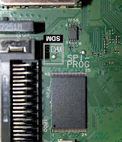
Analogue SDM: use the standard RC-transmitter and key in the code “062596”, directly followed by the “MENU” (or “HOME”) button.
Note: It is possible that, together with the SDM, the main menu will appear. To switch it “off”, push the “MENU” (or "HOME") button again.
Analogue SDM can also be activated by grounding for a moment the solder path on the SSB, with the indication “SDM.
Digital SDM: use the standard RC-transmitter and key in the code “062593”, directly followed by the “MENU” (or "HOME") button.
Note: It is possible that, together with the SDM, the main menu will appear. To switch it “off”, push the “MENU” (or "HOME") button again.
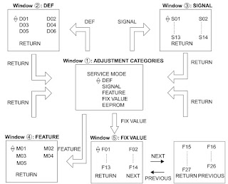
The SAM menu will now appear on the screen. Select ALIGNMENTS and go to one of the sub menus. The alignments are explained below.
The following items can be aligned
• White point
• Ambilight
• TCON Alignment
• Reset TCON Alignment. 
To store the data
• Press OK on the RC before the cursor is moved to the left
• In main menu select “Store” and press OK on the RC
• Switch the set to stand-by mode.
For the next alignments, supply the following test signals via a video generator to the RF input:
• EU/AP-PAL models: a PAL B/G TV-signal with a signal strength of at least 1 mV and a frequency of 475.25 MHz.
US/AP-NTSC models: an NTSC M/N TV-signal with a signal strength of at least 1 mV and a frequency of 61.25 MHz (channel 3).
• LATAM models: an NTSC M TV-signal with a signal strength of at least 1 mV and a frequency of 61.25 MHz (channel 3).
PC mode display adjustment
General set-up
The alignment has to be done in a subdued lighted room. The ambient Light may be maximum 5 NIT.
Equipment requirement
Minolta Color Analyser CA-210 / CS-200 and Quantum Data
802BT Video Test Generator.
Input signal types
Apply full white pattern to the HDMI input, apply 1080p 60 Hz.
Alignment set-up
1. Input pattern for White Point alignment.
2. Press “0 0 0 1 8 3 MUTE” to enter the iTV mode.
3. The alignment has to be made for “Cool”, “Normal” and “Warm” settings.
4. Use a contactless analyzer for the LCD display.
Alignment method
1. Place the colour sensor of the meter at the centre of the screen with standard orientation (at 0 degree orientation).
2. Set the meter in (T, Duv) or (x, y).
3. Set the picture format to Unscaled, set the light sensor to off, set the brightness to 50, set the colour to 50 and set the contrast to 100.
4. Set color temperature to “COOL”.
5. White point red, White point green, White point blue register must be set to maximum value of 128.
6. Press “0 6 2 5 9 6 INFO” to enter BE factory mode.
7. At SAM mode menu, adjust the SCALER_GAIN_R, SCALER_GAIN_G, SCALER_GAIN_B values to meet “COOL” color coordinates specification below. Then store those values to NVM.
Alignment requirement at the center of the screen
Pre-check panel whether the uniformity is correct and check the initial surface luminance, white tone color R/G/B gain = 128.
• 22" panel : > 300 cd/m2.
• 26" panel : > 400 cd/m2.
• 32" panel : > 450 cd/m2.
Adjusting “Scaler Gain” in factory mode. These R/G/B gain value < 128 to avoid saturation at the 11-step grey pattern.
This group setting of color temperature will be applied automatically to the TV / VGA / HDMI / AV sources.
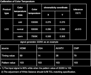
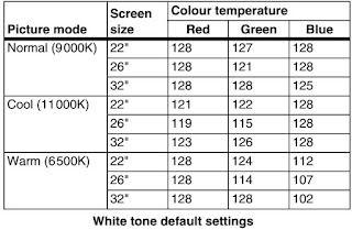
If you do not have a colour analyser, you can use the default values. This is the next best solution. The default values are average values coming from production.
Select a color temperature (e.g. COOL, NORMAL, or WARM).
• Set the RED, GREEN and BLUE default values according to the values in Table below
• When finished press OK on the RC, then press STORE (in the SAM root menu) to store the aligned values to the NVM.
• Restore the initial picture settings after the alignments.
Option Settings
The microprocessor communicates with a large number of I2C ICs in the set. To ensure good communication and to make digital diagnosis possible, the microprocessor has to know which ICs to address.
The presence / absence of these PNX51XX ICs (back-end advanced video picture improvement IC which offers motion estimation and compensation features (commercially called HDNM) plus integrated Ambilight control) is made known by the option codes.
After changing the option(s), save them by pressing the OK button on the RC before the cursor is moved to the left, select STORE in the SAM root menu and press OK on the RC.
• The new option setting is only active after the TV is switched “off” / “stand-by” and “on” again with the mains switch (the NVM is then read again).
Option numbers
Select this sub menu to set all options at once (expressed in two long strings of numbers).
An option number (or “option byte”) represents a number of different options. When you change these numbers directly, you can set all options very quickly. All options are controlled via eight option numbers.
When the NVM is replaced, all options will require resetting. To be certain that the factory settings are reproduced exactly, you must set both option number lines. You can find the correct option numbers on a sticker inside the TV set.
Example: The options sticker gives the following option numbers
 08192 00133 01387 45160
 12232 04256 00164 00000
The first line (group 1) indicates hardware options 1 to 4, the second line (group 2) indicate software options 5 to 8.
Every 5-digit number represents 16 bits (so the maximum value will be 65536 if all options are set).
When all the correct options are set, the sum of the decimal values of each Option Byte (OB) will give the option number.
Diversity
Not all sets with the same Commercial Type Number (CTN) necessarily have the same option code.
Use of Alternative BOM => an alternative BOM number usually indicates the use of an alternative display or power supply. This results in another display code thus in another Option code.
Refer to the sticker in the set for the correct option codes.
Important: after having edited the option numbers as described above, you must press OK on the remote control before the cursor is moved to the left.
Display Code
Reset of Repaired SSB (Small Signal Board)
A very important issue towards a repaired SSB from a Service repair shop (SSB repair on component level) implies the reset of the NVM on the SSB.
A repaired SSB in Service should get the service Set type “00PF0000000000” and Production code “00000000000000”.
Also the virgin bit is to be set. To set all this, you can use the ComPair tool or use the “NVM editor” and “Dealer options” items in SAM (do not forget to “store”).
After a repaired SSB has been mounted in the set (set repair on board level), the type number (CTN) and production code of the TV has to be set according to the type plate of the set. For this (new in this platform), you can use the NVM editor in SAM. This action also ensures the correct functioning of the “Net TV” feature and access to the Net TV portals. The loading of the CTN and production code can also be done via compare (Model number programming).
In case of a display replacement, reset the “Operation hours display” to “0”, or to the operation hours of the replacement display.
SSB identification
Whenever ordering a new SSB, it should be noted that the correct ordering number (12nc) of a SSB is located on a sticker on the SSB. The format is <12nc SSB><serial number>.
The ordering number of a “Service” SSB is the same as the ordering number of an initial “factory” SSB.
Error Codes
The error code buffer contains all detected errors since the last time the buffer was erased. The buffer is written from left to right, new errors are logged at the left side, and all other errors shift one position to the right.
When an error occurs, it is added to the list of errors, provided the list is not full. When an error occurs and the error buffer is full, then the new error is not added, and the error buffer stays intact (history is maintained).
To prevent that an occasional error stays in the list forever, the error is removed from the list after more than 50 hrs. of operation.
When multiple errors occur (errors occurred within a short time span), there is a high probability that there is some relation between them.
New in this chassis is the way errors can be displayed:
• If no errors are there, the LED should not blink at all in
CSM or SDM. No spacer must be displayed as well.
• There is a simple blinking LED procedure for board level repair (home repair) so called LAYER 1 errors next to the existing errors which are LAYER 2 errors.
– LAYER 1 errors are one digit errors.
– LAYER 2 errors are 2 digit errors.
• In protection mode.
– From consumer mode: LAYER 1.
– From SDM mode: LAYER 2.
• Fatal errors, if I2C bus is blocked and the set reboots, CSM and SAM are not selectable.
– From consumer mode: LAYER 1.
– From SDM mode: LAYER 2.
• In CSM mode.
– When entering CSM: error LAYER 1 will be displayed by blinking LED. Only the latest error is shown.
• In SDM mode.
– When SDM is entered via Remote Control code or the hardware pins, LAYER 2 is displayed via blinking LED.
• Error display on screen.
– In CSM no error codes are displayed on screen.
– In SAM the complete error list is shown.
Errors detected by the Stand-by software which lead to protection.
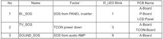
These errors will always lead to protection and an automatic start of the blinking LED LAYER 1 error.
Errors detected by the Stand-by software which not lead to protection.
In this case the front LED should blink the involved error.
Note that it can take up several minutes
before the TV starts blinking the error (e.g. LAYER 1 error = 2, LAYER 2 error = 15 or 53).
• Errors detected by main software (MIPS). In this case
the error will be logged into the error buffer and can be read out via ComPair, via blinking LED method LAYER 1-2 error, or in case picture is visible, via SAM.
How to Read the Error Buffer
Use one of the following methods:
• On screen via the SAM (only when a picture is visible).
E.g.:
– 00 00 00 00 00: No errors detected
– 23 00 00 00 00: Error code 23 is the last and only detected error.
– 37 23 00 00 00: Error code 23 was first detected and error code 37 is the last detected error.
– Note that no protection errors can be logged in the error buffer.
How to Clear the Error Buffer
Use one of the following method:
• By activation of the “RESET ERROR BUFFER” command in the SAM menu.
• If the content of the error buffer has not changed for 50+ hours, it resets automatically.
In case of non-intermittent faults, clear the error buffer before starting to repair (before clearing the buffer, write down the content, as this history can give significant information). This to ensure that old error codes are no longer present.
If possible, check the entire contents of the error buffer. In some situations, an error code is only the result of another error code and not the actual cause (e.g. a fault in the protection detection circuitry can also lead to a protection).
There are several mechanisms of error detection:
• Via error bits in the status registers of ICs.
• Via polling on I/O pins going to the stand-by processor.
• Via sensing of analog values on the stand-by processor or the PNX85500.
• Via a “not acknowledge” of an I2C communication.
Take notice that some errors need several minutes before they start blinking or before they will be logged. So in case of problems wait 2 minutes from start-up onwards, and then check if the front LED is blinking or if an error is logged.
Rebooting. When a TV is constantly rebooting due to internal problems, most of the time no errors will be logged or blinked. This rebooting can be recognized via a compare interface and Hyperterminal (for Hyperterminal settings.)
It’s shown that the loggings which are generated by the main software keep continuing. In this case diagnose has to be done via ComPair.
• Error 13 (I2C bus 3, SSB bus blocked). 
Current situation:when this error occurs, the TV will constantly reboot due to the blocked bus. The best way for further diagnosis here, is to use ComPair.
• Error 14 (I2C bus 2, TV set bus blocked). 
Current situation: when this error occurs, the TV will constantly reboot due to the blocked bus. The best way for further diagnosis here, is to use ComPair.
• Error 18 (I2C bus 4, Tuner bus blocked). 
In case this bus is blocked, short the “SDM” solder paths on the SSB during startup, LAYER error 2 = 18 will be blinked.
• Error 15 (PNX8550 doesn’t boot). 
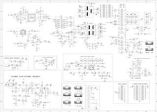
Indicates that the main processor was not able to read his bootscript. This error will point to a hardware problem around the PNX8550 (supplies not OK, PNX 8550 completely dead, I2C link between PNX and Stand-by Processor broken, etc...).
When error 15 occurs it is also possible that I2C1 bus is blocked (NVM). I2C1 can be indicated in the schematics as follows: SCL-UP-MIPS, SDA-UP-MIPS.
LAYER 2 error = 28 will be logged and displayed via the  Other root causes for this error can be due to hardware problems regarding the DDR’s and the bootscript reading from the PNX8550.
• Error 16 (12V). 
This voltage is made in the power supply and results in protection (LAYER 1 error = 3) in case of absence. When SDM is activated we see blinking LED LAYER 2 error = 16.
• Error 17 (Inverter or Display Supply). 
Here the status of the “Power OK” is checked by software, no protection will occur during failure of the invertor or display supply (no picture), only error logging. LED blinking of LAYER 1 error = 3 in CSM, in SDM this gives LAYER 2 error = 17.
• Error 21 (PNX51X0). 
When there is no I2C communication towards the PNX51X0 after start-up, LAYER 2 error = 21 will be logged and displayed via the blinking LED procedure if SDM is switched on. This device is located on the 200 Hz panel from the display.
• Error 23 (HDMI). 
When there is no I2C communication towards the HDMI mux after start-up, LAYER 2 error = 23 will be logged and displayed via the blinking LED procedure if SDM is switched on.
• Error 24 (I2C switch).
 When there is no I2C communication towards the I2C switch, LAYER 2 error = 24 will be logged and displayed via the blinking LED procedure when SDM is switched on. Remark: this only works for TV sets with an I2C controlled screen included.
• Error 28 (Channel dec DVB-S). 
When there is no I2C communication towards the DVB-S channel decoder, blinking LED procedure if SDM is switched on.
Error 31 (Lnb controller). 
When there is no I2C communication towards this device, LAYER 2 error = 31 will be logged and displayed via the blinking LED procedure if SDM is activated.
• Error 34 (Tuner). 
When there is no I2C communication towards the tuner during start-up, LAYER 2 error = 34 will be logged and displayed via the blinking LED procedure when SDM is switched on.
• Error 35 (main NVM). 
When there is no I2C communication towards the main NVM during start-up, LAYER 2 error = 35 will be displayed via the blinking LED procedure when SDM is switched “on”. All service modes (CSM, SAM and SDM) are accessible during this failure,
observed in the Uart logging as follows: "<< ERRO >>> PFPOW_.C: First Error (id19, Layer_1= 2 Layer_= 35)".
• Error 36 (Tuner DVB-S).
 When there is no I2C communication towards the DVB-S tuner during start-up, LAYER 2 error = 36 will be logged and displayed via the blinking LED procedure when SDM is switched “on”.
• Error 42 (Temp sensor). 
Only applicable for TV sets equipped with temperature devices.
• Error 53. 
This error will indicate that the PNX8550 has read his bootscript (when this would have failed, error 15 would blink) but initialization was never completed because of hardware problems (NAND flash, ...) or software initialization problems. Possible cause could be that there is no valid software loaded (try to upgrade to the latest main software version). Note that it can take a few minutes before the TV starts blinking LAYER 1 error = 2 or in SDM, LAYER 2 error = 53.
• Error 64.
 Only applicable for TV sets with an I2C controlled screen.
The LED Blinking LED Procedure
The blinking LED procedure can be split up into two situations:
• Blinking LED procedure LAYER 1 error.
 In this case the error is automatically blinked when the TV is put in CSM. This will be only one digit error, namely the one that is referring to the defective board which causes the failure of the TV. This approach will especially be used for home repair and call
centres. The aim here is to have service diagnosis from a distance.
Blinking LED procedure LAYER 2 error. 
Via this procedure, the contents of the error buffer can be made visible via the front LED. In this case the error contains 2 digits and will be displayed when SDM (hardware pins) is activated. This is especially useful for fault finding and gives more details
regarding the failure of the defective board.
[For an empty error buffer, the LED should not blink at all in CSM or SDM. No spacer will be displayed.]
When one of the blinking LED procedures is activated, the front LED will show (blink) the contents of the error buffer. Error codes greater then 10 are shown as follows
1. “n” long blinks (where “n” = 1 to 9) indicating decimal digit
2. A pause of 1.5 s
3. “n” short blinks (where “n”= 1 to 9)
4. A pause of approximately 3 s,
5. When all the error codes are displayed, the sequence finishes with a LED blink of 3 s (spacer).
6. The sequence starts again.
Example:
 Error 12 8 6 0 0.
After activation of the SDM, the front LED will show
1. One long blink of 750 ms (which is an indication of the decimal digit) followed by a pause of 1.5 s
2. Two short blinks of 250 ms followed by a pause of 3 s
3. Eight short blinks followed by a pause of 3 s
4. Six short blinks followed by a pause of 3 s
5. One long blink of 3 s to finish the sequence (spacer).
6. The sequence starts again.
How to Activate
Use one of the following methods:
• Activate the CSM. The blinking front LED will show only the latest layer 1 error, this works in “normal operation” mode or automatically when the error/protection is monitored by the Stand-by processor.
In case no picture is shown and there is no LED blinking, read the logging to detect whether “error devices” are mentioned.
Activate the SDM. 
The blinking front LED will show the entire content of the LAYER 2 error buffer, this works in “normal operation” mode or when SDM (via hardware pins) is activated when the TV set is in protection.
Software Protections
Most of the protections and errors use either the stand-by microprocessor or the MIPS controller as detection device.
Since in these cases, checking of observers, polling of ADCs, and filtering of input values are all heavily software based, these protections are referred to as software protections.
There are several types of software related protections, solving a variety of fault conditions:
• Related to supplies
 presence of the +5V, +3V3 and 1V2 needs to be measured, no protection triggered here.
• Protections related to breakdown of the safety check mechanism. E.g. since the protection detections are done by means of software, failing of the software will have to initiate a protection mode since safety cannot be guaranteed any more.
(The detection of a supply dip or supply loss during the normal playing of the set does not lead to a protection, but to a cold reboot of the set. If the supply is still missing after the reboot, the TV will go to protection.)
Protections during Start-up
During TV start-up, some voltages and IC observers are actively monitored to be able to optimize the start-up speed, and to assure good operation of all components. If these monitors do not respond in a defined way, this indicates a malfunction of the system and leads to a protection.
Hardware Protections
The only real hardware protection in this chassis appears in case of an audio problem e.g. DC voltage on the speakers. This protection will only affect the Class D audio amplifier  and puts the amplifier in a continuous burst mode (cyclus approximately 2 seconds).
(There still will be a picture available but no sound. While the Class D amplifier tries to start-up again, the cone of the loudspeakers will move slowly in one or the other direction until the initial failure shuts the amplifier down, this cyclus starts over and over again. The headphone amplifier will also behaves similar.)
Ambilight
Due to degeneration process of the LED’s fitted on the ambi module, there can be a difference in the colour and/or light output of the spare ambilight modules in comparison with the originals ones contained in the TV set. Via SAM => alignments
=> ambilight, the spare module can be adjusted.
Audio Amplifier
The Class D-IC 7D10 has a powerpad for cooling. When the IC is replaced it must be ensured that the powerpad is very well pushed to the PWB while the solder is still liquid. This is needed to insure that the cooling is guaranteed, otherwise the Class DIC could break down in short time.
AV PIP
To check the AV PIP board (if present) functionality, a dedicated tespattern can be invoke as follows: select the “multiview” icon in the User Interface and press the “OK” button. Apply for the main picture an extended source, e.g. HDMI input. Proceed by entering CSM (push ‘123654’ on the remote control) and press the yellow button. A coloured testpattern should appear now, generated by the AV PIP board  (this can take a few seconds).
CSM
When CSM is activated and there is a USB stick connected to the TV, the software will dump the complete CSM content to the USB stick. The file (Csm.txt) will be saved in the root of the USB stick. If this mechanism works it can be concluded that a large
part of the operating system is already working (MIPS, USB...)
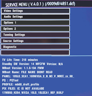
Exit “Factory Mode”
When an “F” is displayed in the screen’s right corner, this means the set is in “Factory” mode, and it normally happens after a new SSB is mounted. To exit this mode, push the “VOLUME minus” button on the TV’s local keyboard for 10 seconds (this disables the continuous mode).
Then push the “SOURCE” button for 10 seconds until the “F” disappears from the screen.
Logging
When something is wrong with the TV set (f.i. the set is rebooting) you can check for more information via the logging in Hyperterminal. The Hyperterminal is available in every Windows application via Programs, Accessories, Communications, Hyperterminal. Connect a “ComPair UART”- cable (3138 188 75051) from the service connector in the TV to the “multi function” jack at the front of ComPair II box.
Required settings in ComPair before starting to log
- Start up the ComPair application.
- Select the correct database (open file “Q55X.X”, this will set the ComPair interface in the appropriate mode).
- Close ComPair
After start-up of the Hyperterminal, fill in a name (f.i. “logging”) in the “Connection Description” box, then apply the following settings:
1. COMx
2. Bits per second = 115200
3. Data bits = 8
4. Parity = none
5. Stop bits = 1
6. Flow control = none
During the start-up of the TV set, the logging will be displayed.
This is also the case during rebooting of the TV set (the same logging appears time after time). Also available in the logging is the “Display Option Code” (useful when there is no picture), look for item “DisplayRawNumber” in the beginning of the logging. Tip: when there is no picture available during rebooting you are able to check for “error devices” in the logging (LAYER 2 error) which can be very helpful to determine the failure cause of the reboot. For protection state, there is no logging.
Uart loggings are displayed
• When Uart loggings are coming out, the first conclusion we can make is that the TV set is starting up and communication with the flash RAM seems to be supported.
The PNX85500 is able to read and write in the DRAMs.
• We can not yet conclude : Flash RAM and DRAMs are fully operational/reliable.There still can be errors in the data transfers, DRAM erros, read/write speed and timing control.
No Uart logging at all
• In case there is no Uart logging coming out, check if the startup script can be send over the I2C bus (3 trials to startup) + power supplies are switched on and stable.
• No startup will end up in a blinking LED status : error LAYER 1 = “2”, error LAYER 2 = “53” (startup with SDM solder paths short).
• Error LAYER 2 = “15” (hardware cause) is more related to a supply issue while error LAYER 2 = “53” (software cause) refers more to boot issues.
Uart loggings reporting fault conditions, error messages, errorcodes, fatal errors
• Failure messages should be checked and investigated.For instance fatal error on the PNX51x0: check startup of the back-end processor, supplies..reset, I2C bus. => error mentioned in the logging as: *51x0 failed to start by itself*.
• Some failures are indicated by error codes in the logging, check with error codes table e.g. => <<<ERROR>>>PLFPOW_MERR.C : First Error (id=10,Layer_1=2,Layer_2=23).
• I2C bus error mentioned as e.g.: “ I2C bus 4 blocked”.
• Not all failures or error messages should be interpreted as fault.For instance root cause can be due to wrong option codes settings => e.g. “DVBS2Suppoprted : False/True.In the Uart log startup script we can observe and check the enabled loaded option codes.
Defective sectors (bad blocks) in the Nand Flash can also be reported in the logging.
Startup in the SW upgrade application and observe the Uart logging:
Starting up the TV set in the Manual Software Upgrade mode will show access to USB, meant to copy software content from USB to the DRAM.Progress is shown in the logging as follows:
“cosupgstdcmds_mcmdwritepart: Programming 102400 bytes,
40505344 of 40607744 bytes programmed”.
Startup in Jett Mode
Check Uart logging in Jet mode mentioned as : “JETT UART READY”.
Uart logging changing preset:
=> COMMAND: calling DFB source = RC6, system=0, key = 4”.
Display option code
Attention: In case the SSB is replaced, always check the display option code in SAM, even when picture is available.
Performance with the incorrect display option code can lead to unwanted side-effects for certain conditions.
New in this chassis
While in the download application (start up in TV mode + “OK” button pressed), the display option code can be changed via 062598 HOME XXX special SAM command (XXX=display option in 3 digits)
PSL
In case of no picture when CSM (test pattern) is activated and backlight doesn’t light up, it’s recommended first to check the inverter on the PSL + wiring (LAYER 2 error = 17 is displayed in SDM).
Tuner
Attention: In case the tuner is replaced, always check the tuner options.

Samsung LED LCD TV-UN46EH6000F-Power Supply LED Board BN44-00498A – Schematic

$
0
0
Used with: Samsung UA40EH5300R, Samsung UN40EH5300G, Samsung UN40EH6000, Samsung UN40EH6050, Samsung UN40EH5000FXZA, Samsung UN40EH6000FXZA TS02 Samsung UN40EH6000FXZA CS01, Samsung UN46EH6000F
 ICs and FETs: SPC7011F, MDF11N60TH SMPS (FET), SQD2011K, FSFR1700XSL, AOD4149 (FET), SLC2012M
Schematic [Circuit diagram]
Click on the schematics to magnify

Sharp LED TV-LC-32LD145, LC-39LD145 – SMPS schematic, How to enter service mode and more

$
0
0
Using Vestel 17IPS19, Vestel 17IPS20S-R6  main digital board - Service mode, Software update, general troubleshooting
SOFTWARE UPDATE
In MB82 project there is only one software for service. From following steps software update procedure.
1. Copy “upgrade loader.pkg”software file directly into foot of a flash memory (not in a folder)
2. Put flash memory to the TV when TV is powered off.
3. Power on and press OK button on the remote control when the TV is opened.
4. If First Time Installation screen appears, it means software update is successful.
There is a full software package (upgrade_loader_full.pkg) only with engineering purpose.  [Do not use because CI+Credentials and HDCP keys will be erased with full software update.]
The DC voltages required at various parts of the chassis and panel is provided by a main power supply unit. MB82 chassis can operate with PW05, IPS60, IPS70, IPS16, IPS17, IPS19, PW25, PW26, PW82-3, PW03, PW04, PW06, PW07 as main power supply and also with 12V adaptor.
Which power board can be used for board to board or cable connection?
Board to board (B TB) :
PW05, I PS60, I PS70, I PS16, I PS17, I PS19 Power Cable : PW25, PW26, PW82-3, PW03, PW04, PW06, PW07
The power supplies generate
24V, 12V, 5V, 3,3V and 12V, 5V, 3.3V stand b y mode DC voltages. Power stage which is on-chassis generates 5V, 3V3 stand by voltage and 12V, 8V, 5V, 3V3, 2.5V, 1,8V and 1,2V supplies for other different parts of the chassis.
 For PW26 and PW27 just common blocks are enough for proper operation.
Short CCT Protection Circuit
Short circuit protection is necessary f or protecting chassis and main IC against damages when any Vcc supply shorts to ground. Protect pin should be logic high while normal operation. When there is a short circuit protect pin should be logic low. After any short detection, SW forces LEDs on LED card to blink.
SERVICE MENU
In order to reach service menu, First Press “MENU” then write "4725" by using remote control. In first screen following items can be seen:
Sharp LC-32LD145 power supply schematic – Vestel 17IPS19 20-40 inch led TV
Sharp LC-39LD145  power supply schematic – Vestel 17IPS20S-R6  39 inch LCE TV
Click on the schematics to magnify
Troubleshooting
No Backlight Problem
Problem: If TV is working, led is normal and there is no picture and backlight on the panel.
Possible causes: Backlight pin, dimming pin, backlight supply, stby on/off pin 
Backlight pin should be high in open position. If it is low, please check Q30 and panel cables
Dimming pin should be high or square wave in open position. If it is low, check S16 for Mstar side and panel or power cables, connectors.
Backlight power supply should be in panel specs. Check CN4 for MB82, related connectors for power supply cards.
STBY_ON/OFF should be low for standby on condition, check R2090.
CI Module Problem
Problem: CI is not working when CI module inserted.
Possible causes: Supply, suply control pin, detect pins, mechanical positions of pins
CI supply should be 5V when CI module inserted. If it is not 5V check CI_POWER_CTRL, this pin should be low.
Check mechanical positions of CI module.
Detect ports should be low. If it is not low please check CI connector pins, CI module pins and 3V3_VCC on MB82.
Led Blinking Problem
Problem: LED blinking, no other operation
This problem indicates a short on Vcc voltages. Protect pin should be logic high while normal operation. When there is a short circuit protect pin will be logic low. If you detect logic low on protect pin, unplug the TV set and control voltage points with a multimeter to find the shorted voltage to ground.
IR Problem
Problem: LED or IR not working
Check LED card supply on MB82 chasis.
Keypad Touchpad Problems
Problem: Keypad or Touchpad is not working
Check keypad supply and KEYBOARD pin on MB82
USB Problems
Problem: USB is not working or no USB Detection.
Check USB Supply, It should be nearly 5V.
No Sound Problem
Problem: No audio at main TV speaker outputs.
Check supply voltages of VDD_AUDIO, 5V_VCC or 12V_VCC with a voltage-meter.
There may be a problem in headphone connector or headphone detect circuit (when headphone is connected, speakers are automatically muted). Measure voltage at HP_DETECT pin, it should be 3.3v.
No sound – headphone
Problem: No audio at headphone output.
Check HP detect pin, when headphone is. Check 5V_VCC and 3V3_VCC with a voltmeter.
Standby On/Off Problem
Problem: Device cannot boot, TV hangs in standby mode.
There may be a problem about power supply. Check 12V_VCC, 5V_VCC and 3V3_VCC with a voltage-meter. Also there may be a problem about SW. Try to update TV with latest SW. Additionally it is good to check SW printouts via hyper-terminal (or Teraterm). These printouts may give a clue about the problem.
No Signal Problem
Problem: No signal in TV mode.
Check tuner supply voltage; 3V3_TUN. Check tuner options are correctly set in Service menu. Check AGC voltage at IF_AGC pin of tuner.

How to update the software, software versions, Function details – using Vestel 17MB82S main digital board - Sharp LED TV LC39LD145

$
0
0
Sharp LC-32LD145E (B), LC-32LD145K(B), LC-32LD145V(B), LC-39LD145E (B), LC-39LD145K(B), LC-39LD145V(B)
Fitted with  Vestel 17MB82S CHASSIS, LED LCD COLOUR TELEVISION - DVB-T / DVB-C (HDTV), PAL B/G, I / SECAM B/G, D/K, L/L’ SYSTEM COLOUR TELEVISION
DIFERENCES BETWEEN MODELS
The new main board has been change from 17MB82-2 to 17MB82S.
The new main board 17MB82S has the possibility to support DVB S/S2
Also new PSU board has been changed from 17IPS20 R5 to 17IPS20S R6 in 39 inches.
* The character is added at the end of the model name on the model label.
* The character is also added at the end of the model name on the carton label.
Software is different from original model.
LC32LD145E
LCD Maker: Vestel LG open cell Panel
LCD Part number: VES315WNDL-01
Power unit board: Vestel 7IPS19-5 V.1 (With LED Driver circuit)
LED Driver board: Vestel 17MB82-2
Software: LC-32LD145E_SW_V058a
LC32LD145E (B)
LCD Maker: Vestel LG open cell Panel
LCD Part number: VES315WNDL-01
Power unit board: 17IPS1917MB82S
LED Driver board: 17MB82S
Software: LC-32LD145E(B)_SW_V066a
LC39LD145E
LCD Maker: Vestel INNORUX open cell
LCD Part number: VES390UNDC-01
Power unit board: 17IPS20 R5 (With LED Driver circuit)
LED Driver board: 17MB82-2
Software: LC-39LD145E_SW_V058a
LC39LD145E (B)
LCD Maker: Vestel INNORUX open cell
LCD Part number: VES390UNDC-01
Power unit board: 17IPS20S R6 (With LED Driver circuit)
LED Driver board: 17MB82S
Software: LC-39LD145E(B)_SW_V066a
Using My button 1 (*) on the remote control
Press MY BUTTON 1 for fve seconds when on a desired source, channel or link, until the “MY BUTTON IS SET” message is displayed on the screen. This confirms that the selected MY BUTTON is now associated with the selected function.
Using My Button 2 (**) on the remote control
Press MY BUTTON 2 for fve seconds when on a desired source, channel or link, until the “MY BUTTON IS SET” message is displayed on the screen. This confirms that the selected MY BUTTON is now associated with the selected function.
17MB82S main board is driven by MediaTek MT5820. 
This IC is capable of handling Video and audio processing, Scaling-Display processing, 3D comb filter, OSD and text processing, LVDS/mini-LVDS transmitting, channel and MPEG2/4 decoding, integrated DVB-T/C demodulator and media center functionality.
TV supports PAL, SECAM, NTSC color standards and multiple transmission standards as B/G, D/K, and I’I including German and NICAM stereo. Also DVB T, DVB-C are supported internal demodulators of MediaTek IC.
Sound system output is supplying max. 2x8W ( less 10%THD at max output)
Supported peripherals are:
1 RF input VHF I, VHF III, UHF @ 75Ohm
1 Side AV (CVBS, R/L_Audio)
1 SCART socket
1 PC input
2 HDMI 1.3 input(2 HDMI input )
1 PDIF output
1 Headphone
1 Common interface
2 USB(1 USB input)
TUNER(MXL601)
MxL601 is a highly integrated low-power silicon tuner IC targeting all global analog and digital cable standards as well as digital terrestrial reception standards. Broadband input filtering and channel filtering have been completely integrated on-chip. This integration enables a very compact design requiring a small footprint, low bill-of-materials cost, and low power consumption. A signal at the 753 RF input is filtered and converted to a programmable IF output up to 44MHz. Automatic gain control, LO generation, and channel selectivity functions are completely integrated on the chip, which simplifies board level design. All functions of the IC can be controlled via I2C interface. MxL601 is available in a 4 x 4 mm2 24-pin QFN package.
AUDIO AMPLIFIER
The TAS5721 is a 15-W stereo or 2x10 W + 1x15 W2.1 device, efficient, digital audio-power amplifier for driving stereo bridge-tied speakers. One serial data input allows processing of up to two discrete audio channels and seamless integration to most digital audio processors and MPEG decoders. The device accepts a wide range of input data and data rates. Awfully programmable data path routes these channels to the internal speaker drivers. The TAS5721 is a slave-only device receiving all clocks from external sources. The TAS5721 operates with a PWM carrier between a 384-kHz switching rate and a 352-KHz switching rate, depending on the input sample rate. Oversampling combined with a fourth- order noise shaper provides a flat noise floor and excellent dynamic range from 20 Hz to 20 kHz.
Features
* Audio Input/Output
15Wx2 into 8
Supports Single Device 0.1, 2.0, 2.1 Modes
Wide PVDD Range, From 4.5 V to 26 V Performance
Efficient Class-D Operation Eliminates Need for Heatsinks
Requires Only 3.3 V and PVDD
One Serial Audio Input (Two Audio Channels)
I2C Address Selection via PIN (Chip Select)
Supports 8-kHz to 48-kHz Sample Rate (LJ/RJ/I2S)
External Headphone-Amplifier Shutdown Signal
Integrated CAP-Free Headphone Amplifier
Stereo Headphone (Stereo 2-V RMS Line Driver) Outputs
* Audio/PWM Processing
Independent Channel Volume Controls With The 24-dB to Mute
Separate Dynamic Range Control for Satellite and Sub Channels
21 Programmable Biquads for Speaker EQ
Programmable Coefficients for DRC Filters
DC Blocking Filters
Support for 3D Effects
* General Features
Serial Control Interface Operational Without MCLK
Factory-Trimmed Internal Oscillator for Automatic Rate Detection
Surface Mount, 48-Pin, 7-mm × 7-mm HTQFP Package
Thermal and Short-Circuit Protection.
POWER STAGE
The DC voltages required at various parts of the chassis and panel are provided by a main power supply unit. MB82 chassis can operate with PW05, IPS60, IPS70, IPS16, IPS17, IPS19, PW25, PW26, PW82-3, PW03, PW04, PW06, PW07 as main power supply and also with 12V adaptor.
Which power board can be used for board to board or cable connection?
Board to b oard (B TB) : PW05, I PS60, I PS70, I PS16, I PS17, I PS19 Power
Cable : PW25, PW26, PW82-3, PW03, PW04, PW06, PW07
The power supplies generate 24V, 12V, 5V, 3,3V and 12V, 5V, 3.3V stand b y mode DC voltages. Power stage which is on-chassis generates 5V, 3V3 stand by voltage and 12V, 8V, 5V, 3V3, 2.5V, 1,8V and 1,2V supplies for other different parts of the chassis. Chassis block diagram is indicated below.
The blocks on power block diagram is using dependent to main supply. For PW26 and PW27 just common blocks are enough for proper operation.
Short CCT Protection Circuit
Short circuit protection is necessary f or protecting chassis and main IC against dam ages when any Vcc supply shorts to ground. Protect pin should be logic high while normal operation. When there is a short circuit protect pin should be logic low. After any short detection, SW forces LEDs on LED card to blink.
MICROCONTROLLER – MediaTek
MT5820 (Main IC) (U1)
The MediaTek MT5820 family consists of a backend decoder and a TV controller and offers high integration for advanced applications. It combines a transport de-multiplexer, a high definition video decoder, an audio decoder, a dual-link LVDS transmitter, a mini-LVDS transmitter, an EPI transmitter and an NTSC/PAL/SECAM TV decoder with a 3D comb filter (NTSC/PAL). The MT5820 enables consumer electronics manufactures to build high quality, low cost and feature-rich DTV.
World-Leading audio/Video Technology: 
The MT5820 supports Full-HD MPEG1/2/4/h.264/DiviX/VC1/RM/AVS/VP6/VP8 (option) video decoder standards, and JPEG. The MT5820 also supports MediaTek MDDiTM de-interlace solution can reach very smooth picture quality for motions. A 3D comb filter added to the TV decoder recovers great details for still pictures. The special color processing technology provides natural, deep colors and true studio quality video. Also, the MT5820 family has built-in high resolution and high-quality audio codec.
Rich Features for High Value Products: 
The MT5820 family enables true single-chip experience. It integrates high-quality HDMI1.4a, high speed VGA ADC, LVDS, mini-LVDS, EPI, USB2.0 receiver, TCON (option),panel overdrive (option).
WW Common Platform Capability: Reserved transport stream input is for external demodulator for other countries or areas. TV maker can easily port the same UI to worldwide TV models. Excellent adjacent and co-channel rejection capability grants customers never miss any wonderful stream. Professional error-concealment provides stable, smooth and mosaic-free video quality.
Panel Supply Switch Circuit
This switch is used to open and close panel supply of TCON. It is controlled by port of main uncontrolled. Also with this circuit panel sequence could be adjusted correctly. 3 panel supplies are connected to this circuit. All of them are optional according to panels.
EN25QH16 16 Megabit Serial Flash Memory with 4Kbyte Uniform Sector
The EN25QH16 is a 16 Megabit (2,048 K-byte) Serial Flash memory, with enhanced write protection mechanisms. The EN25QH16 supports the standard Serial Peripheral Interface (SPI), and a high performance Dual/Quad output as well as Dual/Quad I/O using SPI pins:
Serial Clock, Chip Select, Serial DQ0(DI), DQ1(DO), DQ2(WP#) and DQ3(HOLD#). SPI clock frequencies of up to 80MHz are supported allowing equivalent clock rates of 160MHz (80MHz x 2) for Dual Output and 320MHz (80MHz x 4) for Quad Output when using the Dual/Quad I/O Fast Read instructions. The memory can be programmed 1 to 256 bytes at a time, using the Page Program instruction. The EN25QH16 is designed to allow either single Sector/Block at a time or full chip erase operation. The EN25QH16 can be configured to protect part of the memory as the software protected mode. The device can sustain a minimum of 100K program/erase cycles on each sector or block.
LM1117/LM 800mA Low-Dropout Linear Regulator
The LM1117 is a series of low dropout voltage regulators with a dropout of 1.2V at 800mA of load current. It has the same pin-out as National Semiconductor’s industry standard LM317.
The LM1117 is available in an adjustable version, which can set the output voltage from 1.25V to 13.8V with only two external resistors. In addition, it is also available in five fixed voltages, 1.8V, 2.5V, 2.85V, 3.3V, and 5V. The LM1117 offers current limiting and thermal shutdown. Its circuit includes a zener trimmed bandgap reference to assure output voltage accuracy to within ±1%. The LM1117 series is available in SOT-223, TO-220, and TO-252 D-PAK packages. A minimum of 10MF tantalum capacitor is required at the output to improve the transient response and stability.
SERVICE MENU SETTINGS
In order to reach service menu, First Press “MENU” then write "4725" by using remote control.
In first screen following items can be seen:
SOFTWARE UPDATE
In MB82 project there is only one software for service. From following steps software update procedure.
1. Copy “upgrade loader.pkg”software fle directly into foot of a flash memory (not in a folder)
2. Put flash memory to the TV when TV is powered off.
3. Power on the and press OK button on the remote control when the TV is opened.
4. If First Time Installation screen appears, it means software update is successful.

BN44 00438A, BN44 00468A – SMPS schematic – Samsung LN32D403E2G, LN26D450 LED LCD TV

$
0
0

Samsung LE32D400E1W, Samsung LN26D450G1DXZA, Samsung LN32D450G1DXZA LED LCD TV power board circuit diagram: Used ICs - SEM3040, STRW6052S, SEM2106 
Attaching SMDs
 When soldering the SMD terminals, do not touch them directly with the soldering iron. The soldering should be done as quickly as possible; care must be taken to avoid damage to the terminals of the SMDs themselves.
* Keep the SMD's body in contact with the printed board when soldering.
* The soldering iron to be used (approx. 30 W ) should preferably be equipped with a thermal control (soldering temperature: 225 to 250 C).
* Soldering should not be done outside the solder land.
* Soldering flux (of rosin) may be used, but should not be acidic.
* After soldering, let the SMD cool down gradually at room temperature.
* The quantity of solder must be proportional to the size of the solder land. If the quantity is too great, the SMD might crack or the solder lands might be torn loose from the printed board.
Removal of SMDs
* Heat the solder (for 2-3 seconds) at each terminal of the chip. By means of litz wire and a slight horizontal force, small components can be removed with the soldering iron.
They can also be removed with a solder sucker
* While holding the SMD with a pair of tweezers, take it off gently using the soldering iron's heat applied to each terminal..
* Remove the excess solder on the solder lands by means of litz wire or a solder sucker..
While holding the SMD with a pair of tweezers, take it off gently using the soldering iron's heat applied to each terminal..
* Remove the excess solder on the solder lands by means of litz wire or a solder sucker
LN32D400, LN26D450 Power board [SMPS] and schematic

Click on the schematic to magnify

Viewing all 2033 articles
Browse latest View live


<script src="https://jsc.adskeeper.com/r/s/rssing.com.1596347.js" async> </script>