Service Modes
The Service Mode feature is split into four parts:• Service Alignment Mode (SAM).
• Factory Mode.
• Customer Service Mode (CSM).
SAM and the Factory mode offer features, which can be used by the Service engineer to repair/align a TV set. Some features are:
• Make alignments (e.g. White Tone), reset the error buffer
SAM and Factory Mode.
• Display information (“SAM” indication in upper right corner of screen, error buffer, software version, operating hours, options and option codes, sub menus).
The CSM is a Service Mode that can be enabled by the consumer. The CSM displays diagnosis information, which the customer can forward to the dealer or call centre. In CSM mode, “CSM”, is displayed in the top right corner of the screen.
The information provided in CSM and the purpose of CSM is to:
• Increase the home repair hit rate.
• Decrease the number of nuisance calls.
• Solved customers’ problem without home visit.
Note: For the new model range, a new remote control (RC) is used with some renamed buttons. This has an impact on the activation of the Service modes. For instance the old “MENU” button is now called “HOME” (or is indicated by a “house” icon).
Next items are applicable to all Service Modes or are general.
Life Timer
During the life time cycle of the TV set, a timer is kept (called “Op. Hour”). It counts the normal operation hours (not the Stand-by hours). The actual value of the timer is displayed in SAM in a decimal value. Every two soft-resets increase the
hour by + 1. Stand-by hours are not counted.
Software Identification, Version, and Cluster
The software ID, version, and cluster will be shown in the main menu display of SAM and CSM.
The screen will show: “AAAAAAB-XXX.YYY.MMM.TTT”,
where:
• AAAAAA is the chassis name: TPM165L.
• B is the region indication: E = Europe, A = AP/China, U =
NAFTA, L = LATAM.
• XXX is the main version number: this is updated with a major change of specification (incompatible with the previous software version). Numbering will go from 0- 255.
• YYY is the sub version number: this is updated with a minor change of specification (incompatible with the previous versions). Numbering will go from 0- 255.
• MMM is the number of the mandatory (upgrade) release in association with the area of the mandatory (upgrade) release. Numbering will go from 0 - 255.
• TTT bit 7 to 1 is the area of the mandatory (upgrade) release where 0 - none, 1 - Netflix, rest reserved.
• TTT bit 0 : 0 = development release, 1 = production release.
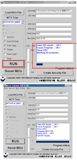
Display Option Code Selection
When after an SSB or display exchange, the display option code is not set properly, it will result in a TV with “no display”.Therefore, it is required to set this display option code after such a repair.
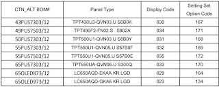
To do so, press the following key sequence on a standard RC transmitter: “062598” directly followed by MENU and “xxx”, where “xxx” is a 3 digit decimal value of the panel type:
When the value is accepted and stored in NVM, the set will switch to Stand-by, to indicate that the process has been completed. During this algorithm, the NVM-content must be filtered, because several items in the NVM are TV-related and not SSB related (e.g. Model and Prod. S/N). Therefore, “Model” and “Prod. S/N” data is changed into “See Type Plate”. In case a call centre or consumer reads “See Type Plate” in CSM mode.
![]()
Service Alignment Mode (SAM)
Purpose
• To modify the NVM.
• To display/clear the error code buffer.
• To perform alignments.
Specifications
• Operation hours counter (maximum five digits displayed).
• Software version, error codes, and option settings display.
• Error buffer clearing.
• Option settings.
• Software alignments (White Tone).
• NVM Editor.
• Set screen mode to full screen (all content is visible).
How to Activate SAM
To activate SAM, use one of the following methods:
• Press the following key sequence on the remote control transmitter: “062596”, directly followed by the “INFO/OK” button. Do not allow the display to time out between entries while keying the sequence.
After entering SAM, the following items are displayed, with “SAM” in the upper right corner of the screen to indicate that the television is in Service Alignment Mode.
How to Navigate
• In the SAM menu, select menu items with the UP/DOWN keys on the remote control transmitter. The selected item will be indicated. When not all menu items fit on the screen, use the UP/DOWN keys to display the next/previous menu items.
• With the “LEFT/RIGHT” keys, it is possible to:
– (De) activate the selected menu item.
– (De) activate the selected sub menu.
– Change the value of the selected menu item.
• When you press the MENU button once while in top level SAM, the set will switch to the normal user menu (with the SAM mode still active in the background)
How to Store SAM Settings
To store the settings changed in SAM mode (except the RGB Align settings), leave the top level SAM menu by using the POWER button on the remote control transmitter or the television set. The mentioned exceptions must be stored separately via the STORE button.
How to Exit SAM
Use one of the following methods:
• Switch the set to STANDBY by pressing the mains button on the remote control transmitter or the television set.
• Via a standard RC-transmitter, key in “00” sequence.
Note: When the TV is switched “off” by a power interrupt while in SAM, the TV will show up in “normal operation mode” as soon as the power is supplied again. The error buffer will not be cleared.
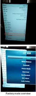
Contents of the Factory mode:
Purpose
• To perform extended alignments.
Specifications
• Displaying and or changing Panel ID information.
• Displaying and or changing Tuner ID information.
• Error buffer clearing.
• Various software alignment settings.
• Testpattern displaying.
• Public Broadcasting Service password Reset.
• etc.
How to Activate the Factory mode
To activate the Factory mode, use the following method:
• Press the following key sequence on the remote control transmitter: from the “menu/home” press “1999”, directly followed by the “Back/Return” button. Do not allow the display to time out between entries while keying the sequence.
After entering the Factory mode, the following items are displayed.
How to Exit the Factory mode
Use one of the following methods:
• Select EXIT_FACTORY from the menu and press the “OK” button.
Note: When the TV is switched “off” by a power interrupt, or normal switch to “stand-by” while in the factory mode, the TV will show up in “normal operation mode” as soon as the power is supplied again. The error buffer will not be cleared.
Customer Service Mode (CSM)
Purpose
The Customer Service Mode shows error codes and information on the TVs operation settings. The call centre can instruct the customer (by telephone) to enter CSM in order to identify the status of the set. This helps the call centre to diagnose problems and failures in the TV set before making a service call.
The CSM is a read-only mode; therefore, modifications are not possible in this mode.
Specifications
• Ignore “Service unfriendly modes”.
Line number for every line (to make CSM language independent).
Set the screen mode to full screen (all contents on screen is visible).
• After leaving the Customer Service Mode, the original settings are restored.
• Possibility to use “CH+” or “CH-” for channel surfing, or enter the specific channel number on the RC.
How to Activate CSM
To activate CSM, press the following key sequence on a standard remote control transmitter: “123654” (do not allow the display to time out between entries while keying the sequence).
After entering the Customer Service Mode, the following items are displayed.
Note: Activation of the CSM is only possible if there is no (user) menu on the screen.
Contents of CSM
• 1.1 Set Type This information is very helpful for a helpdesk/workshop as reference for further diagnosis. In this way, it is not necessary for the customer to look at the rear of the TV-set. Note that if an NVM is replaced or is initialized after corruption, this set type has to be re-written to NVM.
• 1.2 Production code Displays the production code (the serial number) of the TV. Note that if an NVM is replaced or is initialized after corruption, this production code has to be re-written to NVM.
• 1.3 Installation date Indicates the date of the first installation of the TV. This date is acquired via time extraction.
• 1.4a Option Code 1 Gives the option codes of option group 1 as set in SAM.
• 1.4b Option Code 2 Gives the option codes of option group 2 as set in SAM.
• 1.5 SSB Gives an identification of the SSB as stored in NVM. Note that if an NVM is replaced or is initialized after corruption, this identification number has to be re-written to NVM. This identification number is the 12NC number of the SSB.
• 1.6 Display 12NC NVM read/write.
• 1.7 PSU 12NC NVM read/write.
• 1.8 RF4CE 12NC NVM read/write.
• 2.1 Current Main SW Displays the built-in main software version. In case of field problems related to software, software can be upgraded. As this software is consumer upgradeable, it will also be published on the internet. • 2.2 Standby SW Displays the built-in stand-by processor software version. Upgrading this software will be possible via USB.
• 2.3 Panel Code Displays the Display Code number.
• 2.4 Bootloader ID ID of Bootloader.
• 2.5 NVM-version Detects and displays NVM version.
• 2.6 Flash ID ID of flash model.
• 2.7 e-UM version eDFU (help) version.
• 2.8 Channel Table Structure Version version of channel table structure.
• 2.9 Error Codes Detects and displays errors.
• 3.1 Signal Quality Analog/digital signal strength.
• 3.2 Child lock Not active / active. This is a combined item for locks. If any lock (channel lock, parental lock) is active, it is indicated as “active”.
• 3.3 HDCP keys Indicates the validity of the HDMI keys (or HDCP keys). In case these keys are not valid and the customer wants to make use of the HDMI functionality, the SSB has to be replaced.
• 3.4 Ethernet MAC address A Media Access Control address (MAC address) is a unique identifier assigned to network interfaces for communications on the physical network segment.
• 3.5 Wireless MAC address Wireless Media Access Control address.
How to Navigate
By means of the “CURSOR-DOWN/UP” knob (or the scroll wheel) on the RC-transmitter, can be navigated through the menus.
How to Exit CSM
To exit CSM, use one of the following methods.
• Press the MENU/HOME button on the remote control transmitter.
• Press the POWER button on the remote control transmitter.
• Press the POWER button on the television set.
Software Upgrading
It is possible for the user to upgrade the main software via the USB port. This allows replacement of a software image in a stand alone set. A description on how to upgrade the main software can be found in the DFU or on the Philips website.
Preparing a portable memory for software upgrade
The following requirements have to be met:
1. A personal computer connected to the internet.
2. An archive utility that supports the ZIP-format (e.g. WinZip for Windows or Stufflt for Mac OS).
3. A FAT formatted USB memory stick (preferably empty).
Check the current TV software version
Before starting the software upgrade procedure, it is advised to check that what the current TV software:
1. Press the “1 2 3 6 5 4” button on the remote control to enter the CSM mode.
2. Use the up/down cursor keys to select “Current Main Software”.
If the current software version of the TV is the same as the latest update file found on http://www.philips.com/support, it is not necessary to update the TV software.
Download the latest software
1. Open the internet page http://www.philips.com/support.
2. Find information and software related to the TV.
3. Select the latest software update file and download it to the PC.
4. Insert the USB memory stick into one of the USB ports of the PC.
5. Decompress the downloaded ZIP file and copy it to the root directory of the USB flash drive.
Update the TV software
1. Turn the TV on and wait for it to boot completely.
2. Insert the USB memory stick that contains the software update files in one of the TV’s USB ports.
3. The TV will detect the USB memory stick automatically. Then a window jumps out.
Note: If the USB flash drive is not detected after power up, disconnect it and re-insert it.
4. Select [Update] and press OK.
5. To proceed, In next menu select [Start] and press OK to start software updates.
6. Upgrading will now begins and the status of the updating progress will be displayed.
7. When the TV software is updated. Remove your USB flash drive, then select [Restart] and press OK to restart the TV.
Note:
• Do not remove the USB flash drive during the software update.
• If a power failure occurs during the update, do not remove the USB flash drive from the TV. The TV will continue the software update as soon as the power comes up again.
• If an error occurs during the update retry the procedure or contact the dealer.
• We do not recommend downgrading to an older version.
• Once the upgrade is finished, use the PC to remove the TV software from the USB portable memory.
Content and Usage of the One-Zip Software File
Below you find a content explanation of the One-Zip file, and instructions on how and when to use it. Only files that are relevant for Service are mentioned here.• EDID_clustername.zip: Contains the EDID content of the different EDID NVMs.
• FUS_clustername_version.zip: Contains the file downloaded which is needed to upgrade the TV main software and the software download application.
• NVM_clustername_version.zip: Default NVM content.
How to Copy NVM Data to/from USB
When copying data to and from a USB memory stick, the folder “repair” is used. When inserting an empty USB memory stick, and downloading data to the stick, the TV will create this folder.
When sending data from a USB memory stick to a TV, the intended data must be available in the “repair” folder.
Note that when copying EDID data to the TV, all necessary EDID files must be in this folder.
Error Codes
Introduction
Error codes are required to indicate failures in the TV set. In principle a unique error code is available for every:
• Activated (SW) protection.
• Failing I2C device.
• General I2C error.
The last five errors, stored in the NVM, are shown in the Service menu’s. This is called the error buffer.
The error code buffer contains all errors detected since the last time the buffer was erased. The buffer is written from left to right. When an error occurs that is not yet in the error code buffer, it is displayed at the left side and all other errors shift one
position to the right.
An error will be added to the buffer if this error differs from any error in the buffer. The last found error is displayed on the left.
An error with a designated error code never leads to a deadlock situation. It must always be diagnosable (e.g. error buffer via OSD or blinking LED).
In case a failure identified by an error code automatically results in other error codes (cause and effect), only the error code of the MAIN failure is displayed.
How to Read the Error Buffer
You can read the error buffer in three ways:
• On screen via the SAM/CSM (if you have a picture).
Example:
– ERROR: 000 000 000 000 000: No errors detected
– ERROR: 013 000 000 000 000: Error code 13 is the last and only detected error
– ERROR: 034 013 000 000 000: Error code 13 was detected first and error code 34 is the last detected (newest) error
• Via the blinking LED procedure (when you have no picture).
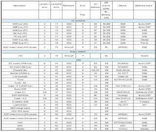
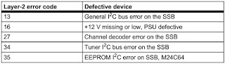
Error codes
In this chassis only “layer 2” error codes are available and point to problems on the SSB. They are triggered by LED blinking when CSM is activated. Only the following layer 2 errors are defined:
How to Clear the Error Buffer
The error code buffer is cleared in the following cases:
• By using the CLEAR command in the SAM menu
• By using the CLEAR command in the Factory mode:
• By using the following key sequence on the remote control transmitter: “062599” directly followed by the OK button.
• If the contents of the error buffer have not changed for 50 hours, the error buffer resets automatically.
Note: If you exit SAM by disconnecting the mains from the television set, the error buffer is not reset.
The Blinking LED Procedure
The software is capable of identifying different kinds of errors. Because it is possible that more than one error can occur over time, an error buffer is available, which is capable of storing the last five errors that occurred. This is useful if the OSD is not
working properly.
Errors can also be displayed by the blinking LED procedure.
The method is to repeatedly let the front LED pulse with as many pulses as the error code number, followed by a period of 1.5 seconds in which the LED is “off”. Then this sequence is repeated.
Example (1): error code 4 will result in four times the sequence LED “on” for 0.25 seconds / LED “off” for 0.25 seconds. After this sequence, the LED will be “off” for 1.5 seconds. Any RC command terminates the sequence. Error code LED blinking is
in red color.
Example (2): the content of the error buffer is “12 9 6 0 0” After entering SAM, the following occurs.
• 1 long blink of 5 seconds to start the sequence.
• 12 short blinks followed by a pause of 1.5 seconds.
• 9 short blinks followed by a pause of 1.5 seconds.
• 6 short blinks followed by a pause of 1.5 seconds.
• 1 long blink of 1.5 seconds to finish the sequence.
• The sequence starts again with 12 short blinks.
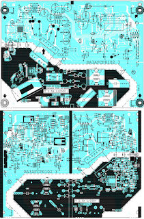
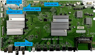
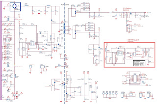
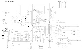
SMPS schematic
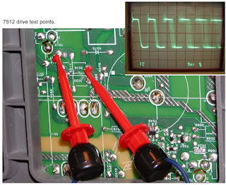
LED driver
How to Activate Blinking LED Procedure
Use one of the following methods:
• Activate CSM.The blinking front LED will show the layer 1 error(s), this works in “normal operation” mode or automatically when the error/protection is monitored by the standby processor.
In case no picture is shown and there is no LED blinking, read the logging to detect whether “error devices” are mentioned.
Activate SAM. The blinking front LED will show the entire content of the LAYER 2 error buffer, this works in “normal operation” mode.
Fault Finding and Repair Tips
Note:
• It is assumed that the components are mounted correctly with correct values and no bad solder joints.
• Before any fault finding actions, check if the correct options are set.
NVM Editor
In some cases, it can be convenient if one directly can change the NVM contents. This can be done with the “NVM Editor” in SAM mode. With this option, single bytes can be changed.
Caution:
• Do not change these, without understanding the function of each setting, because incorrect NVM settings may seriously hamper the correct functioning of the TV set!
• Always write down the existing NVM settings, before changing the settings. This will enable you to return to the original settings, if the new settings turn out to be incorrect
No Picture via HDMI input
Check if HDCP key is valid. This can be done in CSM
TV Will Not Start-up from Stand-by
Possible Stand-by Controller failure. Re-flash the software.
Audio Amplifier
The Class D-IC U601 has a powerpad for cooling. When the IC is replaced it must be ensured that the powerpad is very well pushed to the PWB while the solder is still liquid. This is needed to insure that the cooling is guaranteed, otherwise the Class
D-IC could break down in short time.
Loudspeakers
Make sure that the volume is set to minimum during disconnecting the speakers in the ON-state of the TV. The audio amplifier can be damaged by disconnecting the speakers during ON-state of the set.
Display option code
Attention: In case the SSB is replaced, always check the Panel Code in CSM, even when picture is available. Performance with the incorrect display option code can lead to unwanted side-effects for certain conditions.