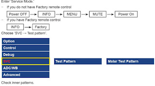
How to enter the service mode, how to make a service remote control, Universal remote control set-up codes for Emerson, sylvania and Symphonic CTVs
To Enter the Service Mode
Optical sensors system is used for Tape Start and End Sensor on this equipment. Read this carefully and prepare as described before starting to service; otherwise, the unit may operate unexpectedly.
Cover Q202 (START SENSOR) and Q201 (END SENSOR) with Insulation Tape or enter the service mode to activate Sensor Inhibition automatically.
Note: Avoid playing, rewinding or fast forwarding the tape to its beginning or end, because both Tape End Sensors are not active.
Service Mode
1. Turn power on.
2. Use service remote control unit and press "DISC MENU" key.
3. When entering the service mode, one of the numbers (1, 2 or 4) will display at corners of the screen.
4. During the service mode, electrical adjustment mode can be selected by remote control key. (Service remote control unit).
How to make service remote control unit
Prepare normal remote control unit
(Part No. NE222UD --- [ 6727DE ])
(Part No. NE223UD --- [ EWC27T4 ])
Remove 4 screws from the back lid.
Cut off pin 10 of the remote control microprocessor and short circuit pins 10 and 17 of the microprocessor with a jumper wire.
To Set up the Service mode
Use the service remote control unit.2. Turn the power on. (Use main power on the TV unit.)
3. To enter the TV mode, press "CH o / p" button on the TV unit.
4. Press "DISC MENU" button on the service remote control unit. Version of micro computer will display on the CRT.
X-Ray protection test should be done when replacing any parts of this chassis.
1. Short both ends of R592 (on Sub CBA).
2. Confirm that the main power turns off.
3. If the main power does not turn off, then replace the following parts (D591, Q591, R592, R593, R594 and IC201)
DC 120V (+B) AdjustmentSymptom of Misadjustment: The picture is dark and unit does not operate correctly.
Note: D613 Cathode (+B), HEAT SINK, VR601 --- Main CBA
1. Connect the unit to AC Power Outlet.
2. Connect DC Volt Meter to D613 Cathode (+B) and HEAT SINK (GND).
3. Adjust VR601 so that the voltage of D613 Cathode (+B) becomes +120±1.0V DC.
CONTRAST, COLOR, TINT and V-TINT Data Values.
Enter the Service mode
2. Press "PICTURE" button on the service remote control unit. Display changes "BRT,""CNT,""COL,""TNT," and "V-TNT" cyclically when "PICTURE" button is pressed.
CONTRAST (CNT)
1. Press "PICTURE" button on the service remote control unit. Then select "CONTRAST (CNT)" display.
2. Press "CH Up/Dn” buttons on the service remote control unit so that the value of "CONTRAST (CNT)" becomes 90.
COLOR (COL)
1. Press "PICTURE" button on the service remote control unit. Then select "COLOR (COL)" display.
2. Press "CH Up/Dn" buttons on the service remote control unit so that the value of "COLOR (COL)" becomes 58
TINT (TNT)
1. Press "PICTURE" button on the service remote control unit. Then select "TINT (TNT)" display.
2. Press "CH Up/Dn" buttons on the service remote control unit so that the value of "TINT (TNT)" becomes 57.
V-TINT (V-TNT)
1. Press "PICTURE" button on the service remote control unit. Then select "V-TINT (V-TNT)" display.
2. Press "CH Up/Dn" buttons on the service remote control unit so that the value of "V-TINT (V-TNT)" becomes 56.
Note: BRIGHT data value does not need to be adjusted at this moment.
Setting for Y DL Time TV, Y DL Time EXT, Y SW LPF, Black Stretch Off, Black Stretch CONT and C. Angle Data Values
1. Enter the Service mode.
2. Y DL Time TV Adjustment: Press "0" button on the service remote control unit twice to show "D-T TV" on the display.
Y DL Time EXT Adjustment: Press "0" button on the service remote control unit three times to show "D-T EXT" on the display.
Y SW LPF Adjustment: Press "0" button on the service remote control unit four times to show "Y SW" on the display.
Black Stretch Off Adjustment: Press "0" button on the service remote control unit five times to show "B-S" on the display.
Black Stretch CONT Adjustment: Press "0" button on the service remote control unit six times to show "BS2" on the display.
C. Angle Adjustment: Press "0" button on the service remote control unit seven times to show "CANG" on the display.
3. Y DL Time TV Adjustment: Select "2" by pressing "CH Up/Dn" buttons on the service remote control.
Y DL Time EXT Adjustment: Select "2" by pressing "CH Up/Dn" buttons on the service remote control.
Y SW LPF Adjustment: Select "0" by pressing "CH Up/Dn" buttons on the service remote control.
Black Stretch Off Adjustment: Select "OFF" by pressing "CH Up/Dn" buttons on the service remote control.
Black Stretch CONT Adjustment: Select "0" by pressing "CH Up/Dn" buttons on the service remote control.
Angle Adjustment: Select "103" by pressing "CH Up/Dn" buttons on the service remote control.
Setting for CD-VOL, DVD-BRT and DVD-SHARP Data Values
1. Enter the Service mode.
2. CD-VOL Adjustment: Press "VOL UP" button on the service remote control unit once to show "CD VOL" on the display.
DVD-BRT Adjustment: Press "VOL UP" button on the service remote control unit twice to show "DVD BRT" on the display.
DVD-SHARP Adjustment: Press "VOL UP" button on the service remote control unit three times to show "DVD SHP" on the display.
3. CD-VOL Adjustment: Select "7" by pressing "CH Up/Dn" buttons on the service remote control.
DVD-BRT Adjustment: Select "0" by pressing "CH Up/Dn" buttons on the service remote control.
DVD-SHARP Adjustment: Select "0" by pressing "CH Up/Dn" buttons on the service remote control.
H fo Adjustment
Purpose: To get correct horizontal position and size of screen image.
Symptom of Misadjustment: Horizontal position and size of screen image may not be properly displayed.
Note: R583 --- Sub CBA
1. Connect frequency counter to R583.
2. Operate the unit for at least 20 minutes.
3. Enter the Service mode. Press "2" button on the remote control unit and select HADJ mode.
4. Press "CH Up/Dn" buttons on the remote control unit so that the display will change "0" to "7."
5. At this moment, choose display "0" to "7" when the frequency counter display is closest to 15.734kHz±300Hz.
6. Turn the power off and on again.
Cut-off Adjustment
Purpose: To adjust the beam current of R, G, B, and screen voltage.
Symptom of Misadjustment: White color may be reddish, greenish or bluish.
Notes: Screen Control --- FBT (Sub CBA), FBT= Fly Back Transformer,
Use the Remote Control Unit.
1. Degauss the CRT and allow the unit to operate for 20 minutes before starting the alignment.
2. Input the Black raster signal from RF input.
3. Enter the Service mode.
4. Press the "VOL DN" button.
(Press "VOL DN" then display will change CUT OFF/
DRIVE and 7Fh adjustment).
5. Choose CUT OFF/DRIVE mode then press "1" button. This adjustment mode is CUT OFF (R).
6. Increase the screen control so that the horizontal line just appears on the CRT.
7. Press the "CH Up/Dn" button until the horizontal line becomes white.
8. Choose CUT OFF/DRIVE mode then press "2" button. This adjustment mode is CUT OFF (G). Press "CH Up/Dn" until the horizontal line becomes white.
9. Choose CUT OFF/DRIVE mode then press "3" button. This adjustment mode is CUT OFF (B). Press "CH Up/Dn" until the horizontal line becomes white.
10.Turn the power off and on again.
H. Size Adjustment
Purpose: To obtain correct size of screen image.
Symptom of Misadjustment: Size of screen image may not be properly displayed.
Note: VR531 --- Sub CBA
1. Input Monoscope pattern.
2. Adjust VR531 so that the size of Monoscope pattern are equal to each other. (90+1%/-5%)
H. Pincushion Adjustment
Purpose: To obtain straight line on the screen.
Symptom of Misadjustment: Straight line image may not be properly displayed.
Note: VR530 --- Sub CBA
1. Input Cross hatch pattern.
2. Adjust VR530 so that the lines of the Cross hatch pattern become straight.
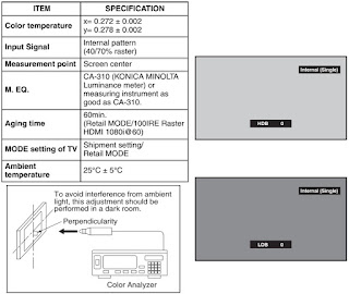
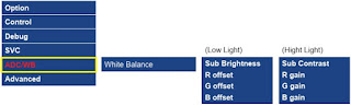
White Balance Adjustment
Purpose: To mix red, green and blue beams correctly for pure white.
Symptom of Misadjustment: White becomes bluish or reddish.
Use service remote control unit
1. Operate the unit more than 20 minutes.
2. Face the unit to the east. Degauss the CRT using a degaussing coil.
3. Input the White Raster (APL 100%).
4. Set the color analyzer to the CHROMA mode and after zero point calibration, bring the optical receptor to the center on the tube surface (CRT).
5. Enter the Service mode. Press "VOL DN" button on the service remote control unit and select "C/D" mode. (Display changes "C/D" and "7F" cyclically when "VOL DN" button is pressed.)
6. Press "4" button on the service remote control unit for Red adjustment. Press "5" button on the service remote control unit for Blue adjustment.
7. In each color mode, press "CH Up/Dn" button to adjust the values of color.
8. Adjust Red and Blue color so that the temperature becomes 9200K (x: 286 / y: 294) ±3%.
9. At this time, re-check that horizontal line is white. If not, re-adjust Cut-off Adjustment until the horizontal line becomes pure white.
10. Turn off and on again to return to normal mode. Receive APL 100% white signal and confirm that Chroma temperatures become 9200K (x: 286 / y: 294) ±3%.
Note: Confirm that Cut Off Adj. is correct after this adjustment, and attempt Cut Off Adj. if needed.
Sub-Brightness Adjustment
Purpose: To get proper brightness.
Symptom of Misadjustment: If Sub-Brightness is incorrect, proper brightness cannot be obtained by adjusting the Brightness Control.
Note: SMPTE Setup level --- 7.5 IRE
1. Enter the Service mode.
Then input SMPTE signal from RF input.
2. Press "PICTURE" button. (Press "PICTURE" button then display will change BRT, CNT, COL, TNT, and V-TNT). Select BRT and press "CH Up/Dn" buttons so that the bar is just visible.
3. Turn the power off and on again.
Focus Adjustment
Purpose: Set the optimum Focus.
Symptom of Misadjustment: If Focus Adjustment is incorrect, blurred images are shown on the display.
Note: Focus VR --- FBT (Sub CBA), FBT= Fly Back Transformer
1. Operate the unit more than 30 minutes.
2. Face the unit to the East and degauss the CRT using a degaussing coil.
3. Input the monoscope pattern.
4. Adjust the Focus Control on the FBT to obtain a clear picture.
Position Adjustment
Purpose: To obtain correct horizontal position and size of screen image.
Symptom of Misadjustment: Horizontal position and size of screen image may not be properly displayed.
Enter the Service mode.
1. Press "8" button on the remote control unit and select H-P mode.
2. Input monoscope pattern.
3. Press "CH Up/Dn" buttons on the remote control unit so that the left and right side of the monoscope pattern are equal to each other.
4. Turn the power off and on again.
V. Shift AdjustmentPurpose: To obtain correct vertical position of screen image.
Symptom of Misadjustment: If V. position is incorrect, vertical position of image on the screen may not be properly displayed.
Enter the Service mode.1. Press "9" button on the remote control unit and select V-P mode. (Press "9" button then display will change to V-P and V-S).
2. Input monoscope pattern.
3. Press "CH Up/Dn" buttons on the remote control unit so that the top and bottom of the monoscope pattern are equal to each other.
V. Size Adjustment
Purpose: To obtain correct vertical height of screen image.
Symptom of Misadjustment: If V. Size is incorrect, vertical height of image on the screen may not be properly displayed.
Enter the Service mode.
1. Press "9" button on the remote control unit and select V-S mode. (Press "9" button then display will change to V-P and V-S).
2. Input monoscope pattern.
3. Press "CH Up/Dn" buttons on the remote control unit so that the monoscope pattern is 90±5% of display size and the circle is round.
Head Switching Position Adjustment (this is an important adjustment)
Purpose: Determine the Head Switching Position during Playback.
Symptom of Misadjustment: May cause Head Switching Noise or Vertical Jitter in the picture.
Note: Unit reads Head Switching Position automatically and displays it on the screen (Upper Left Corner).
1. Playback test tape (FL8A, FL8N).
2. Enter the Service mode.
Then press the number "5" button on the remote control unit.
3. The Head Switching position will display on the screen; if adjustment is necessary follow step 4. 6.5H(412.7µs) is preferable.
4. Press "CH UP" or "CH DN" button on the remote control unit if necessary. The value will be changed in 0.5H steps up or down. Adjustable range is up to 9.5H. If the value is beyond adjustable range, the display will change as:
Lower out of range: 0.0H
Upper out of range: -.-H
5. Turn the power off and on again.
The following 2 adjustments normally are not attempted in the field. They should be done only when replacing the CRT then adjust as a preparation.
Purity Adjustment
Purpose: To obtain pure color.
Symptom of Misadjustment: If Color Purity Adjustment is incorrect, large areas of color may not be properly displayed.
This becomes RED COLOR if the 7KEY is pressed while in service mode.
1. Set the unit facing east.
2. Operate the unit for over 30 minutes before adjusting.
3. Fully degauss the unit using an external degaussing coil.
4. Set the unit to the AUX mode which is located before CH2 then input a red raster from video in.
5. Loosen the screw on the Deflection Yoke Clamper and pull the Deflection Yoke back away from the screen.
6. Loosen the Ring Lock and adjust the Purity Magnets so that a red field is obtained at the center of the screen. Tighten Ring Lock.
7. Slowly push the Deflection Yoke toward the bell of the CRT and set it where a uniform red field is obtained.
8. Tighten the clamp screw on the Deflection Yoke.
Convergence Adjustment
Purpose: To obtain proper convergence of red, green and blue beams.
Symptom of Misadjustment: If Convergence Adjustment is incorrect, the edge of white letters may have color edges.
1. Set the unit to the AUX mode which is located before CH2 then input a dot or crosshatch pattern.
2. Loosen the Ring Lock and align red with blue dots or crosshatch at the center of the screen by rotating (RB) C.P. Magnets.
3. Align red / blue with green dots at the center of the screen by rotating (RB-G) C.P. Magnet.
4. Fix the C.P. Magnets by tightening the Ring Lock.
5. Remove the DY Wedges and slightly tilt the Deflection Yoke horizontally and vertically to obtain the best overall convergence.
6. Fix the Deflection Yoke by carefully inserting the DY Wedges between CRT and Deflection Yoke.
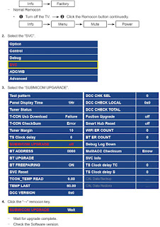
FIRMWARE RENEWAL
Turn the power on and press [SELECT] button on the remote control unit to put the DVD player into DVD mode. Then remove the disc on the tray.
(It is possible to move to F/W version up mode only when the DVD player is in DVD mode with the tray opened.)
2. To put the DVD player into F/W version up mode, press [9], [8], [7], [6], and [SEARCH MODE] buttons on the remote control unit in that order.
The DVD player can also enter the version up mode with the tray open. In this case, Fig. a will be shown on the screen while the tray is open.
3. Load the disc for version up.
4. The DVD player enters the F/W version up mode automatically. Fig. c appears on the screen. If you enter the F/W for different models, “Disc Error” will appear on the screen, then the tray will open automatically.
The appearance shown in (*2) of Fig. c is described as follows:
State | Appearance | No. |
Reading... | Sending files into the memory | 1 |
Erasing... | Erasing previous version data | 2 |
Programming... | Writing new version data | 3 |
5. After programming is finished, the tray opens automatically. Fig. e appears on the screen and the checksum in (*3) of Fig. e
At this time, no buttons are available.
6. Remove the disc on the tray.
7. Press [SELECT] button on the remote control unit to go to TV mode, or press [POWER] button on the unit to turn the power off.
8. Press [SELECT] button on the remote control unit to put the DVD player into DVD mode again.
9. Press [1], [2], [3], [4], and [DISPLAY] buttons on the remote control unit in that order. Fig. g appears on the screen.
10.Press [CLEAR] button on the remote control unit. Fig. h appears on the screen.
When “OK” appears on the screen, the factory default will be set. Then the firmware renewal mode is complete.
11.To exit this mode, press [CH UP/DOWN] or [SELECT] button to go to TV mode, or press [POWER] button to turn the power off.
Fixed Voltage (or Auto voltage selectable) power supply circuit is used in this unit.
If Main Fuse (F2601) is blown, first check to see that all components in the power supply circuit are not defective before you connect the AC plug to the AC power supply. Otherwise it may cause some components in the power supply circuit to fail.
SMPS circuit diagram [Schematic]
The deck mechanism assembly is mounted on the Main CBA directly, and SW211 (REC-SAFETY SW) is mounted on the Main CBA. When deck mechanism assembly is removed from the Main CBA due to servicing, this switch cannot be operated automatically.
1. To eject the tape, press the "STOP/EJECT" button on the unit (or Remote Control).
2. When you want to record during the Service mode, press the "Rec" button while depressing SW211 (REC-SAFETY SW) on the Main CBA.Universal remote control code list
EMERSON: 0004 0042 0049 0065 0101 0113 0119 0145 0152 0166 0191 0214 0215 0225 0324 0378 0421 0456 0460 0604 0611 0654
SYLVANIA: 0392
SYMPHONIC: 0392 0459 0510 0447 0810 0354