Quantcast
Channel: Electro help
Viewing all 2033 articles
Browse latest View live

Sony HCD SHAKEX3 – factory mode, error codes, Power amplifier schematic

$
0
0

Sony HCD-SHAKEX1/SHAKEX3/SHAKEX7 - DVD RECEIVER
AEP Model. UK Model. Australian Model ---- HCD-SHAKEX1/SHAKEX3
E Model ---- HCD-SHAKEX1/SHAKEX3/SHAKEX7
HCD-SHAKEX1 is the tuner, USB, DVD Player, Bluetooth, NFC and amplifier section in SHAKE-X1D. 
HCD-SHAKEX3 is the tuner, USB, DVD Player, Bluetooth, NFC and amplifier section in SHAKE-X3D. 
HCD-SHAKEX7 is the tuner, USB, DVD Player, Bluetooth, NFC and amplifier section in SHAKE-X7D.

DVD Mechanism Type:   CDM90-DVBU204//M
CDM90-DVBU204//M:   CMS-S76RFG1 OR CMS-S76RFGP
SHAKE-X7D
Power Output (rated)::  800 W + 800 W (at 8 ohms, 100 Hz, 1% THD)
RMS output power (reference)::  1,200 W + 1,200 W (per channel at 8 ohms, 100 Hz)
SHAKE-X3D
Power Output (rated): 400 W + 400 W (at 4 ohms, 100 Hz, 1% THD)
RMS output power (reference):  600 W + 600 W (per channel at 4 ohms, 100 Hz)
SHAKE-X1D
Power Output (rated):  400 W + 400 W (at 4 ohms, 100 Hz, 1% THD)
RMS output power (reference):  600 W + 600 W (per channel at 4 ohms, 100 Hz)
* Keep the temperature of the soldering iron around 270 °C during repairing.
* Do not touch the soldering iron on the same conductor of the circuit board (within 3 times).
* Be careful not to apply force on the conductor when soldering or unsoldering.
Notes on laser diode emission check
The laser beam on this model is concentrated so as to be focused on the disc reflective surface by the objective lens in the optical pickup block. Therefore, when checking the laser diode emission, observe from more than 30 cm away from the objective lens.
The laser diode in the optical pick-up block may suffer electrostatic break-down because of the potential difference generated by the charged electrostatic load, etc. on clothing and the human body.
During repair, pay attention to electrostatic break-down and also use the procedure in the printed matter which is included in the repair parts.  The flexible board is easily damaged and should be handled with care.
How to Pair this system with a Bluetooth device
1. Press the [Power1] button to turn the power on.
2. Place the Bluetooth device within 1 meter from the system.
3. Press BLUETOOTH on the unit to select Bluetooth function. “BLUETOOTH” appears in the display panel.
4. Hold down BLUETOOTH on the unit for 2 seconds or more. “PAIRING” flashes in the display panel.
5. Perform the pairing procedure on the Bluetooth device.
6. Select the model number of the unit on the display of the Bluetooth device.( For example, select “SONY:SHAKE-X1D or SHAKE-X3D or SHAKE-X7D”.)
If passkey is required on the Bluetooth device, enter “0000”.
7. Perform the Bluetooth connection on the Bluetooth device.
8. When pairing is completed and the Bluetooth connection is established, Bluetooth device name appears in the display panel.
9. To cancel pairing operation, hold down BLUETOOTH on the unit for 2 seconds or more until “BLUETOOTH” appears in the display panel.
How to connect with a Smartphone by one touch (NFC)
Note: The operation in this mode must use a NFC-compatible Smartphone (Smartphone’s with a built-in NFC function [OS: Android 2.3.3 or later, excluding Android 3.x])
1. Press the [Power] button to turn the power on.
2. Download and install the app “NFC Easy Connect”.
Download the free Android app from Google Play by searching for “NFC Easy Connect”.
3. Start the app “NFC Easy Connect” on the Smartphone.
Make sure that the application screen is displayed.
4. Touch the Smartphone to the N-Mark on the system until the Smartphone vibrates.
Complete the connection by following the instructions displayed on the Smartphone.
5. When pairing is completed and the Bluetooth connection is established, the Bluetooth device name appears in the display panel.
How to Play music from a Bluetooth device
For a Bluetooth device
1. Press the [\/1] button to turn the power on.
2. Press BLUETOOTH on the unit to select Bluetooth function. “BLUETOOTH” appears in the display panel.
3. Establish connection with the Bluetooth device.  Press BLUETOOTH on the unit to connect to the last connected Bluetooth device.
Perform the Bluetooth connection from the Bluetooth device if the device is not connected.
Once the connection is established, the Bluetooth device name appears in the display panel.
Press =► Depending on the Bluetooth device,
– you may have to press =►  twice.
You may need to start playback of an audio source on the Bluetooth device.
For an NFC-compatible Smartphone
Press the [Power] button to turn the power on.
Touch the Smartphone to the N-Mark on the system to establish the Bluetooth connection.
Start playback of an audio source on the Smartphone. For details on playback, refer to the operating instructions of your Smartphone.
To disconnect the Bluetooth device
For a Bluetooth device
Press BLUETOOTH on the unit. “BLUETOOTH” appears in the display panel.
For an NFC-compatible Smartphone
Touch the Smartphone to the N-Mark on the system again.
To erase all the pairing registration information perform COLD RESET test mode
Test mode
panel test mode
This mode is used to check the fluorescent indicator tube, LEDs, keys, [VOLUME/MULTI CONTROL] knob, model, destination and software version.
Procedure:
1. Press [
<] button and [S3 TUNING ‒ ◄] button simultaneously and hold 3 seconds.
2. All LEDs and segments in fluorescent indicator tube are lighted up. All RGB LEDs are lighted up in white color.
3. When you want to enter to the software version display mode, press [S2
0+] button.
The model information appears on the fluorescent indicator tube.  Press [S20+] button again to view the destination information.
4. During the destination information display, press [S2 0+] button. Each time [S2 0+] button is pressed, the fluorescent indicator tube shows the version of each category software in the following sequence: SC, MTK, OPU, UI, PF, SUB, SYS, CD, CMA, CMB, ST, TA, TM and return back to model information display.
5. When [<] button is pressed while the version numbers are being displayed except model and destination, the date of the software creation appears. When [<] button is pressed again, the display returns to the software version display.
6. Press [S1 0‒] button, the key check mode is activated.
7. In the key check mode, the fluorescent indicator tube displays “K 0 V0”.
Each time a button is pressed, “K” value increases. However, once a button has been pressed, it is no longer taken into account.
“V” value increases in the manner of 0, 1, 2, 3 ... if [VOLUME/ MULTI CONTROL] knob is turned clockwise, or it decreases in the manner of 0, 9, 8, 7 ... if [VOLUME/MULTI CONTROL] knob is turned counterclockwise.
8. When [ENTER] button is pressed after all LEDs and segments in fluorescent indicator tube light up, alternate segments in fluorescent indicator tube and LEDs would light up, all RGB LEDs would light up in RED color. If you press [ENTER] button again, another half of alternate segments in fluorescent indicator tube and LEDs would light up, all RGB LEDs would light up in GREEN color. Pressing [ENTER] button again would cause all segments in fluorescent indicator tube and LEDs light up, all RGB LEDs would light up in blue color.
Pressing [ENTER] button again would turn off all segments in fluorescent indicator tube and all LEDs including RGB LEDs.
9. To release from this mode, press the buttons in the same manner as step 1, or disconnect the power cord.
User reset
The user reset clears all data including preset data stored in the data flash to initial conditions exclude history mode data.
Procedure:
1. Press the Power/1button to turn on the system.
2. Press [DJ OFF] button and [S4 TUNING +>] button simultaneously for 3 seconds.
3. “RESET” appears on the fluorescent indicator tube. After that, the fluorescent indicator tube becomes blank for a while, and the system is reset.
Cold reset
The cold reset clears all data including preset data stored in the
data flash to initial conditions included history mode data. Execute
this mode when returning the set to the customer.
Procedure:
1. Press [Power1] button to turn on the system.
2. Press [
<] button and [S4 TUNING +►►] button simultaneously for 3 seconds.
3. “COLD RESET” appears on the fluorescent indicator tube.
After that, the fluorescent indicator tube will display “SONY DEMO”. The set will automatically Power ON and Power OFF again, and the system is reset.
Disc tray lock mode
This mode let you lock the disc tray. When this mode is activated, the disc tray will not open when [Eject] button is pressed. The message “LOCKED” will be displayed on the fluorescent indicator tube.
This mode only applied when there is disc on the tray.
Procedure:
1. Press [Power1] button to turn on the system.
2. Select DVD/CD function.
3. Press [DJ OFF] button and [ISOLATOR] button simultaneously and hold down until “LOCKED” or “UNLOCKED” displayed on the fluorescent indicator tube (around 5 seconds).
Bluetooth pairing history clear
It can clear the Bluetooth pairing history.
Procedure:
1. Press the [Power1] button to turn the power on.
2. Press the [BLUETOOTH] button to turn the Bluetooth function.
3. Press [DJ OFF] button and [
0‒] button simultaneously for 3 seconds.
4. The message “BT HISTORY” → “CLEAR” is displayed on the fluorescent indicator tube, and the pairing history of Bluetooth is cleared.
History mode
This mode is used to check important data stored in the system when PROTECTOR happen.
Procedure:
1. During demo mode, press [
<] button and [S2 0+] button for 5 seconds to mode into history mode.
2. Press the [S4 TUNING +►►|] button or [S3 TUNING ‒ |◄◄ ] button to check history data stored.
To release from History Mode.
To release from this mode, press [Power] button.
Protect Type Description
01 =è The over current condition to MOSFET occurs by defect of MOSFET or defect of PS output line
OR
Unusual heat up of MOSFET by improper assembly of heat sink, destruction of MOSFET etc
02 =èDefect of thermistor IC or charging circuit used by SPM (Sound Pressure Management) system.
03 =èDefect of power supply circuit to AMP. There is possibility of unusual power supply of any of the AMP IC or Pre-amplifier.
04 =è DC appears in SP terminal by defect of AMP IC and MOSFET.
05 =èDefect of DC FAN and DC FAN driver circuit.
If speaker does not have output even if the set status is not in PROTECT mode, the following defect might be possible
RESET defect > Reset signal status from micom is not ‘H’
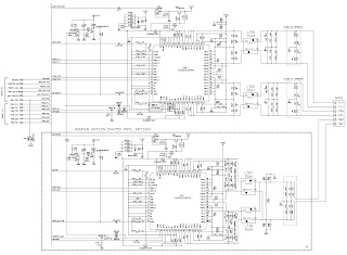
4CH D-Amp board schematic and pwb
DVD service mode
• This mode let you make diagnosis and adjustment easily by using the remote commander and the TV. The instructions, diagnostic results, etc. are given on the on-screen display.
Test disc list
Be sure to use the DVD disc that matches the signal standards of your region.
• CD
YEDS-18 (Part No.: 3-702-101-01)
PATD-012 (Part No.: 4-225-203-01)
HLX-A1 (Part No.: J-2501-307-A)
• DVD SL (Single Layer)
NTSC : HLX-503 (Part No.: J-6090-069-A)
HLX-504 (Part No.: J-6090-088-A)
HLX-513 (Part No.: J-2501-305-A)
PAL : HLX-506 (Part No.: J-6090-077-A)
• DVD DL (Double Layer)
NTSC : HLX-501 (Part No.: J-6090-071-A)
HLX-505 (Part No.: J-6090-089-A)
HLX-514 (Part No.: J-2501-306-A)
PAL : HLX-507 (Part No.: J-6090-078-A)
To enter to DVD Service Mode
Press the [Power] button to turn on the system.
2. Press [FUNCTION +] or [FUNCTION ‒] at remote commander to select DVD/CD function.
3. Press the [SPEAKER LIGHT] button and [ENTER] button simultaneously and hold 3 seconds.
4. The message “SERVICE IN” appears on the fluorescent indicator tube.
The display of the “Model Name” of the “Remocon Diagnosis Menu” change with the model and the destination appears on screen display. Refer to below on the model name.
SHAKE-X1D : TETSUJIN
SHAKE-X3D : RAIJIN
SHAKE-X7D : RYUJIN
5. To execute each function, press its number by using numeric button on the remote commander.
6. To release from this mode, press the [Power] button to turn off the system.
Execute IOP Measurement
In order to execute IOP measurement, the following standard procedures must be followed.
1. From the Top Menu of Remocon Diagnosis Menu, select “2. Drive Manual Operation” by pressing the [2] button on the remote commander. The following screen appears on the onscreen display.
2. Select “3. Manual Adjustment” by pressing the [3] button on the remote commander. The following screen appears on the on-screen display.
3. Select “6. Iop:” by pressing the [6] button on the remote commander.
4. Wait until a hexadecimal number appears in the on-screen display.
5. Convert data from hexadecimal to decimal by using conversion table.
6. Please find the label on the rear of the BU (Base Unit).  The default IOP value is written in the label.
7. Subtract between these two values.
8. If the remainder is smaller than 93 (decimal), then it is OK.  However if the value is higher than 93, then the BU is defective and need to be change.
9. Press the [RETURN] button on the remote commander to return to previous menu.
10. Press the [0] button on the remote commander to return to the Top Menu of Remocon Diagnosis Menu.
11. Press the [Power] button to turn off the system.
Check Emergency History
From the Top Menu of Remocon Diagnosis Menu, select “3. Emergency History” by pressing the [3] button on the remote commander.
2. You can check the total time when the laser is turned on during playback of DVD and CD from the above menu. The maximum time, which can be displayed are 999h 59min.
3. You can check the error code of latest 10 emergency history from the above menu. To view the previous or next page of emergency history, press the [|<<] button or [>>|] button on the remote commander. The error code consists of “Error
Code”, “Parameter of error code” and “Time of error code”
The meaning of error codes.
01: Communication error (No reply from syscon)
02: Syscon hung up
03: Power OFF request when syscon hung up
19: Thermal shutdown
24: MoveSledHome error
25: Mechanical move error (5 Changer)
26: Mechanical move stack error
30: DC motor adjustment error
31: DPD offset adjustment error
32: TE balance adjustment error
33: TE sensor adjustment error
34: TE loop gain adjustment error
35: FE loop gain adjustment error
36: Bad jitter after adjustment
40: Focus NG
42: Focus layer jump NG
51: Spindle stop error
52: Open kick spindle error
60: Focus on error
61: Seek fail error
62: Read Q data/ID error
70: Lead in data read fail
71: TOC read time out (CD)
80: Can’t buffering
81: Unknown media type.
To clear the Laser Hours
Press the [DISPLAY] button and then press the [CLEAR]  button. The data for both CD and DVD data are reset.
To clear the Emergency History
Press the [DVD TOP MENU] button and then press the [CLEAR] button.
The error code for all emergency history would be reset.
To clear the Initialize Setup Data
Press the [DVD/TUNER MENU] button and then press the [CLEAR] button on the remote commander.
To return to the Top Menu of Remocon Diagnosis Menu
Press the [0] button on the remote commander.
To check the version information
From the Top Menu of Remocon Diagnosis Menu, select “4. Version information” by pressing the [4] button on the remote commander.
To return to the Top Menu of Remocon Diagnosis Menu, press the [0] button on the remote commander.


UE32ES5500, UE26EH4500 – Samsung LCD TV – firmware update, troubleshooting, PIN reset, calibration and more

$
0
0

Samsung X10+ LED TV - UE32ES5500(5700), UE40ES5500(5700), UE46ES5500(5700)
UE32EH5300, UE40EH5300, UE46EH5300, UE26EH4500, UE22ES5400 
ES5700 : DVB-T/C/S2 Model
When you want to initialize the TV setting, use the 'reset' menu. Initial PIN number : '0-0-0-0
(If you want change the PIN number, use the Change PIN function located 'System-Security' menu.)
After you execute 'Reset' function, All the settings will return to factory default.
If you forget the PIN code, press the remote control buttons in the following sequence in Standby mode, which resets the PIN to 0,0,0,0:
[MUTE 8,2,4, Power ON.]
How to check the SW version
Use the main menu
 Click the "menu" key in remote controller.
 Select Support menu.
 Locate the menu cursor "Software Upgrade" menu.
 Click the "info" key.
 Check the Main SW and SubMicom SW Version.
How to Upgade Main SW and Micom
Insert the USB device containing the firmware upgrade downloaded from Samsung.com into TV.  Be careful not to disconnect the power or the USB drive while upgrades are being applied.  The TV will turn off and turn on automatically after completing the firmware upgrade.  Check the firmware version after the upgrade are complete [the new version will have higher number than the older version].  When the software is upgraded, video and audio setting you have made will return to their default [factory] settings.  It is recommended you to write down your settings before the beginning of the firmware update.  After update is completed, restore the previous settings.
How to Upgrade Main SW
Store the SW program named –T-MST10PDEUC” in USB memory stick.
Connect the USB
Click the Menu key in remote control.
Select Support Menu
Locate the menu cursor :Software Upgrade” menu.
Click the Enter key.
How to Upgrade SubMicom SW
Store the SW program named “SubmicomEU_10***” in USB memory stick.
Connect the USB.
Enter the factory.
Locate the cursor “SVC” menu.
Click Enter key.
Locate the cursor ‘SUBMICOM UPGRADE” menu.
Click on the pictures to magnify
Troubleshooting

This Troubleshooting is based on E5500(5700) Model.

No Power – troubleshooting table and possible fault locations

No video  HDMI 1, 2, 3 – Digital signal – troubleshooting table &  possible fault locations
No video – Tuner_CVBS – Troubleshooting and possible fault  locations
No video – Tuner DTV – troubleshooting and fault locations
No video AV – troubleshooting and fault locations
No video – Component – troubleshooting and fault locations
No sound – Speaker, Headphone out, Optical – troubleshooting and fault locations
Calibration

Samsung SUHD TV UE49KS9000T, UE55KS9000T, UE65KS9000T – troubleshooting, SMPS board voltages, software update and more

$
0
0

Samsung 49, 55, and 65 inch curved LCD TVs
Check list for initial operation
1. Check the various cable connections frst.
- Check to see if there is a burnt or damaged cable.
- Check to see if there is a disconnected or loose cable connection.
- Check to see if the cables are connected according to the connection diagram.
2. Check the power input to the Main Board.
3. How to distinguish if the problem is caused by Main Board or T-CON Board.
- No Video
If the problem is No Video but BLU is on and Indication LED is blinking repeatedly and faster than normal booting: Replace the T-CON Board.
TV POWER STANDBY
1. TV in Standby
√ Standby LED Indicator
2. If Not Lit:
√ AC 120Vac Line
3. If missing:
√ 120Vac Source and Power Cord
4. If OK:
√ Resistance on SMPS Fuse after frst removing AC power cord.
5. If fusses are open replace SMPS.
6. If fuses are OK:
√ Standby: A13V (Always On) to Main Board. Should all be approx. 9 VDC
7. If any missing remove the SMPS connector to Main Board .
√ Standby A13V again for 9VDC.
- If OK replace Main Board.
- If still missing replace SMPS.
FUNCTION/IR Control
TV in Standby
√ LED Status
2. If LED is OFF
√ LED 1.7Vdc (pin 8) and VCC for 3.3Vdc (pin 3)
• If missing suspect Function Assy/Cable Assy/Main Assy.
3. If LED is ON
√ Switch Operation activates on screen display.
- If missing:
√ Key _Input1 Pin 6 change to 0V with a command.
- If wrong voltage or no change:
√ Switch for stuck or miss-operation.
4. Check IR operation with Standard Remote command changes. (3.3V to 2.5V effective DC) SDA5. , SCL for effective 3.3Vdc (after power on)
- If missing suspect Function Assy/Cable Assy/Main Assy.

BACKLIGHTS
Activate Backlights Test:
1 - Disconnect Lead Cable from Main Board to Power Supply.
√ TV Screen for active backlight LEDs.
2. If NO BACKLIGHTS
√ Minus (Control) & Plus pins (Supply) on the Panel Connector voltages to the Panel.
- If no pin voltages replace SMPS.
3. If BACKLIGHTS ON BUT PANEL SECTION(S) OFF
√ The Supply Drive + pins. All should measure same.
- If a + pin measures higher voltage, a string(s) of LEDs are likely open.
- Remove Panel connector and verify same open backlight voltage condition. Replace Panel.
4. If a + pin measures low voltage disconnect connector to panel
√ The Low Plus Pin Voltage again.
- If it stays low the SMPS is defective, if it goes high, defective Panel.
For BACKLIGHT DIMMING PROBLEMS:
• Go to Menu £ Picture £ Backlight and vary level (0 – 20)
• If no backlight changes observed:
√ Panel Connector minus (-) pin voltages and P-DIM voltages (CNL801) while changing backlight level.
• If minus Panel voltages don’t change, and P-DIM changes, replace SMPS.
• If P-DIM doesn’t change replace Main/T-CON Board.
MUTE 4 1 9 EXIT to test Panel Backlight Sections
ONE CONNECT MINI
If No Video Disconnect OCB Cable.
√ "Disconnect Banner" Displayed.
2. If Banner Appears.
√ One Connect Box / Cable (defective).
3. If No Banner continue.
Video Operation : Generated on Main Section.
If OK:1.
√ Source & Input Cables.
√ Other inputs.
√ One Connect Cable/Box.
2. If Noisy:
√ T-CON Section Test Patterns.
Video Operation : Generated at Pre FRC, of T-CON Section.
If OK:1.
√ Main Section.
2. If Noisy:
√ Post FRC Pattern.
Video Operation : Generated at Post FRC of T-CON Section.
If OK:1.
√ Main / T-CON Board (defective).
2. If Noisy:
√ Mute - 369 – Mute
Video Operation : Generated at T-CON Section.
If OK:1.
√ Main / T-CON Board (defective).
2. If Noisy:
√ Main / T-CON Board.
AUDIO
• No TV Sound
√ Menu → Audio → Speaker Settings set to TV Speaker
• Noisy / Distorted TV Audio
√ Customer Menu → Support → Sound Test
• If Sound Test FAILS : (Missing / Noisy Audio)
√ Speakers (compare resistance/quality)
• Compare audio level out to speakers with multi meter.
√ Replace defective Speakers or Main Board or Cable.
• IF Sound Test OK :
√ Audio Source & External Cables.
√ With external Audio Generator (device or App).
√ Other Inputs.
√ One Connect Mini.
• Optical Digital Out Errors
√ Red light from Optical Digital Out.
• If missing replace One Connect Mini.
No HDMI Audio
√ Source / HDMI Cable & One Connect Mini Connectors.
• Swap with other HDMI Inputs/Sources.
• Perform EDID Write in Factory Mode (Can restore missing HDMI Audio).
√ Bulletins and Latest frmware on TV.
• If not restored replace One Connect Mini/Main.
• Check Audio Format PCM/Dolby based on external Receiver.
• ARC Issues
√ HDMI Cable is input to the ARC Designated HDMI port.
√ ARC (HDMI Control) is enabled on the external Receiver.
• Bluetooth Audio "Sound Share" Connection Issues
√ Sound Bar is in TV Mode.
• To Connect, Press & Hold Play Button until Sound Bar pairing mode begins.
Network - TV to Router "Failure"
• Wired & Wireless MAC Address in Customer Support Menu.
√ No Wired MAC Address: Replace Main Board.
√ No Wireless MAC Address: Module cabling & voltages from Main Board.
√ If operating voltages are OK but signal missing.
• Replace WiFi Module (WiFi/Bluetooth Module).
• Proper security passcode
√ Check Wi-Fi signal strength at TV (use WiFi Analyzer or similar App).
• Try another source (Hot spot or Test Router).
√ Check related Bulletins.
√ Check Factory Mode → SVC → Info → WiFi Error Count (replace module for high error counts).
Router to Network "Failure"
• Instruct the customer the TV has proper connection to the router and is likely OK.
√ Check other devices using network are OK. If they test OK this does not mean the TV should be working.
• Try another source (Hotspot) to test/show TV Network operation.
Smart Hub
Go to Menu > Support > Self Diagnosis > Smart Hub Connection Test
Factory ModeWith Factory Remote
1. Power TV ON.
2. Select TV Source.
3. Info → Factory.
4. Use MENU for return.
With Samsung IR Remote (Limited Operation)
1. TV Power Standby.
2. Press as follows.
• Remote Button : INFO MENU MUTE Power
• Option (must set Option Bytes when replacing Main Board.)
• Option → Factory Reset (returns TV to out of box condition. Does not reset Apps.)
• SVC → Test Patterns
• SVC → Info → ER Count (Important to check for errors.)
- Resets to 0 with Factory Reset.
First Screen Appearing in Factory Mode (SAMPLE)
Factory Reset
Setting Option Bytes
1. Enter Factory Mode with Service Remote (only).
2. Check Option Byte Table located on GSPN (Fast Track or Tips).
3. Select each item to change.
4. Soft power TV Off to load.
Check Test Patterns
1. Verify "Scaler Pattern" and "US Post Pattern".
2. Verify "FRC Pre Test Pattern".
3. Verify "FRC Post Test Pattern".
4. Verify "SoC TCON Test Pattern".
• WD Count: Watch Dog (Hardware related issue).
• AR Count: Auto Reset (software (i.e. Apps) related.
- important Error Count Status Screen.
• Verify each item listed.
Remove ALL HDMI connections.
2. Factory Mode → Control → EDID. (→ Enter Key)
Updating the TV’s Software
View your TV's software version and update it if necessary.
• Settings > Support > Software Update
Updating the TV’s software to the latest version
• Settings > Support > Software Update > Update now
You can update your TV’s software by downloading the update from the Internet directly to your TV or copying the update from a USB device that contains it to your TV.
• Updating from the Internet requires an active Internet connection.
• To update using a USB flash drive, download the update package from Samsung.com to your computer. Then, save the update package in the USB device's top-level folder. Otherwise, the TV will not be able to locate the update package.
[DO NOT turn off the TV’s power until the update is complete. The TV will turn off and on automatically after completing the software update. All video and audio settings return to their default settings after a software update]
Updating the TV automatically
• Settings > Support > Software Update > Auto Update
If the TV is connected to the Internet, you can have the TV's software update itself automatically while you are watching the TV. When the background update is completed, it is applied the next time the TV is turned on.
• This function may take a longer time if another network function is running concurrently.
• This function requires an Internet connection.
• If you agree to the Smart Hub terms and conditions, Auto Update is set to On automatically. If you do not want the TV's software to update itself automatically, set Auto Update to Off.
SMPS POWER
1. Power TV On.
√ PS_ON. 2Vdc (when off) changes to 3.3Vdc (on)
- May already be On if IoT USB is loaded or TV Smart Things Hub mode is active.
2. if voltage error or no change.
√ Jog Function Control Test.
3. If OK replace Main Board.
√ All A13V supplies to full voltage level 12.7VDC.
4. If any wrong voltage, remove the SMPS connector to Main Board.
√ A13V again for 12.7VDC.
5. If OK replace Main Board.
6. If still wrong voltage replace SMPS.
√ OD (Over Voltage Detect) : 3.3Vdc (Operating Normal)
7. If 0V or changing, an SMPS or Panel error exists.
8. Perform Backlight Test.
√ Backlight On/Off 0V Off to 5Vdc ON.
√ If missing/error replace Main Board.
SMPS board and pin map

Haier HL32D2 – Haier HL42XD2 LCD TV – How to enter the factory mode, Service mode adjustments - Power board (SMPS) schematic

$
0
0
Haier HL32D2&HL42XD2 - 31.5”&42” LCD TV - Horizontal Frequency 31~68 KHz
Television System:  NTSC standard,ATSC standard (8-VSB, Clear-QAM)
Take care during handling the LCD module with backlight unit
-Must mount the module using mounting holes arranged in four corners.
-Do not press on the panel, edge of the frame strongly or electric shock as this will result in damage to the screen.
-Do not scratch or press on the panel with any sharp objects, such as pencil or pen as this may result in damage to the panel.
-Protect the module from the ESD as it may damage the electronic circuit (C-MOS).
-Make certain that treatment person’s body is grounded through wristband.
-Do not leave the module in high temperature and in areas of high humidity for a long time.
-Avoid contact with water as it may a short circuit within the module.
-If the surface of panel becomes dirty, please wipe it off with a soft material. (Cleaning with a dirty or rough cloth may damage the panel.)
AUDIO MENU
It provides audio adjustment for user to modify the audio setting. Audio language setting is only available with ATSC TV source, the option is disable under other source modes.
Sound Mode: Choose the audio mode: Personal, Music, or Speech.
2. Bass: Bass tone adjustment, the tuning range is 0 ~ 63. (The default state is enabled.)
3. Treble: Treble tone adjustment, the tuning range is 0 ~ 63. (The default state is enabled.)
4. Balance: Audio balance adjustment, the tuning range is L50 ~ R50.
5. Audio Source: Select the audio source from Mono, Stereo, or SAP. (This function works in ATV only.)
6. Audio Language: Change the audio language setting on ATSC TV programs. The number of the supported audio languages depends on the ATSC TV programs. (English / Français / Español)
7. SPDIF: Digital audio output format. Select from RAW and PCM. (This function works in DTV only.)
8. Speaker: Choose to turn on / off the TV internal speaker. The digital audio output signals and earphone output signals will not be turned off even though the TV speaker is off. The default setting is On.
9. AVL: Choose On or Off to adjust volume to be consistent across programs and channels automatically.
10. Preset: Restore the default audio settings.
Password Setting: Change the 4-numeral parental control password. Three steps are required for changing the password: Enter Old Password -> Enter New Password ->Confirm New Password. Note:
This item is only available in TV, Composite and S-Video source modes. The default password is  0 0 0 0
Parental Control: Provide the parental Control (V-chip) function setting. Before entering the Parental Control sub-menu, user has to key in the password first. Enter the Parental Lock item, then the user can modify the restricted table about MPAA or TV Rating respectively. While exiting the sub-menu, the parental control function is working. The inhibitive channels or source signals can be unlock through key in the correct password.
Note: This feature is only available in TV, Composite and S-Video source modes.(The default password is: 0 0 0 0.)
[Button Lock]– Select On or Off to lock or unlock the control buttons on the side panel of the TV. When this function enables, the control buttons on your TV will be locked and TV only can be controlled by remote control only.
[Block Unrated TV]– When Block Unrated TV is set to on, your TV will block unrated program.
[USA Parental Locks] – Set the parental control level by MPAA or TV Rating.
[Canadian Parental Locks]– Set the parental control level by English Rating or French Rating.
[Open V-Chip]– Open V-Chip is an advanced V-Chip rating system for digital channels that are received.
The rating table will be updated by downloading the RRT5 data for blocking.
6. Closed Captions: Select a closed caption options. (Off / On / With Mute)
7. Analog Captions: Select an analog caption options. (CC 1-4 / TEXT 1-4)
8. Digital Captions: Select a digital caption options. (SERVICE 1-6)
9. Digital Captions Setup: Provide numerous options for setting the digital closed caption style in the sub-menu.
[Style]– Set to Automatic or Customer mode. If Custom mode is selected, user can modify the detail styles described below. The setting result will be shown immediately on the bottom of the submenu OSD. Note: This feature is only available in Digital TV (ATSC) mode.
[Size]– Digital closed caption font size, which can be set as Automatic, Small, Normal, or Large.
[Font]– Digital closed caption font style, which can be chosen as Automatic, Default, or Font 1 ~ 7.
[Text Color]– Automatic / White / Red / Green / Blue / Yellow / Magenta / Cyan / Black.
[Text Opacity]– Automatic / Solid /Flashing / Transparent / Translucent.
[Background Color]– Automatic /Black / White/ Red / Green / Blue / Yellow /Magenta / Cyan.
[Background Opacity]– Automatic /Solid / Flashing / Transparent / Translucent.
[Edge Effect]– Automatic / None/ Raised / Depressed / Uniform / Left / Shadow / Right Shadow.
[Edge Color]– Automatic / Red / Green / Blue / Yellow / Magenta / Cyan / Black / White.
10. Input Labels: User can edit the input labels.
11. Component Setting: This option only shows and is available in component mode, which provides fine tuning component display.
[Phase]– Adjust Picture Phase to reduce Horizontal-Line noise. The tuning range is from 0 to 31.
[Preset]– Restore the default component setting values.
12. MultiMedia Menu: This option shows the photos in JPEG formats and plays the music in MP3 formats that stored in a USB storage device. Note: File number is limited to 1000 files.
JPEG sizes are limited as followed:
For 19"/32": 10928x6114
For 24"/42": 15360x8640
There are two ways to enter JPEG Viewer and MP3 Music Box interface: After plugging USB storage device into USB hub, Multimedia List menu will display.
Select MultiMedia Menu in Feature Menu to choose JPEG Viewer or MP3 MusicBox. These two items are activated only if the USB storage device is plugged into the USB hub.
[JPEG Viewer]  Press Menu to display control menu. Press Enter to enlarge the selected photo (orange frame) in browser.
 Image Delay: Set display time for each picture in slide show. There are three options: Fast, Slow, and Normal.
 Music On Slide Show: Enable background Music during slide show. It will play with the MP3 file sequence in current folder repeatedly. Music On Slide Show item will be grayed out if there is no MP3 file in current folder.
Start Slide Show: Enter Slide Show mode.
Rotate Photo: Rotate selected picture. (0/90/180/270)
•• Back to Upper Folder: Return to the upper folder.
•• Back to Root Folder: Return to root folder.
•• Back To Browser: Return to Browser mode. (Photo page with control menu.)
•• Exit: Exit JPEG Viewer and return to original source. (Browser with Control menu.)
13. Reset to Default: Restore all the default settings.
AV IN (AV/S-VIDEO)– Connect the input source for composite video devices, such as a VCR or video game. Use the white and red connectors to connect the external audio from the same source. The signal being carried by the
S-Video cable and connector, if connected, will take priority over the Video RCA connector (yellow connector).
COMPONENT (Y/Pb/Pr with Audio L/R)– Connect the primary source for component video devices such as a DVD Player or set top box here. Use red for Pr, blue for Pb, green for Y, red for right audio (R) and white for left
audio (L) inputs.
SPDIF (Optical Digital Audio Out)– When a digital audio signal is associated with the input selected for viewing, the digital audio will be available on this SPDIF connection to your home theater system.
Haier SMPS [Power supply board] schematic [HL32D2]
Adjustment
No need to adjust the white balance for this model, do ADC only.
Step1: Turn on the TV, press “Menu”, then press number key 1 > 9 > 9 > 9 and “ENTER”, it will achieve the factory mode.
Step2: Change TV, press the “Current Source” to Component mode and change signal to 1080i mode, press the “Auto Color”
Step3: Change TV, press the “Current Source” to PC mode and change signal to PC TIMING 137(1024X768); Pattern 147 (16 Grays), press the “Auto Color”
Universal remote control set-up codes for Haier TVs: 0328 0601 0658

LG 29FS4RK, LG 29FS4RK-L1 – 29 inch CTV – schematic and service adjustments

$
0
0
Used ICs: TDA7297(Audio amplifier), TDA120xx(UOC), TDA6107ajf(RGB Amp),TDA9326(Vertical amp), 2SC6090(Horizontal Out Transistor), STR6556(SMPS control), BSC2B-N2334(FBT)
(1) Because this is an insulated chassis, it is not necessary use an isolation transformer. However, the use of the isolation transformer will help protect the test instrument.
(2) The adjustment must be made in the correct order.
(3) The adjustment must be made given the circumstance of 25 ± 5 ° C temperature and 65 ± 10% relative humidity if there is no specific designation.
(4) The AC input voltage of the receiver must maintain a nominal voltage during adjustment.
(5) The receiver must be operated for about 15 minutes before to make the adjustment.
(6) Signal: The standard color signal is approved in 65 ± 1dBμV. The standard color signal means the pattern signal digital.
Adjustment
Adjust the volume of the Top Focus of the FBT for the best focus of the vertical line of the fourth part of the screen (Red circle)
Manual Screen Adjustment
(Using ADJ (ADJUST) of the Remote Control)
(1) Receive the NTSC (PAL) signal in RF mode without considering the channel.
(2) If you press the "ADJ" button in the LINE SVC mode (INSTART button), the LINE SVC mode changes to the setting mode of the screen.
(3) Adjust the SCREEN so that all OK appears on the HBC and WBC using SCREEN VOL. FBT (Press the button ADJ to exit SVC mode)
Sub-brightness adjustment
(1) If you press the "ADJ" button on the remote control to adjust Setting mode "SCREEN" (SCREEN), the mode changes to the Secondary Brightness setting mode.
(Sub-brightness adjustment mode: Channel 14, MIN CONTRAST / BRIGHTNESS)
(2) Adjust until the "2" almost disappears in the Scale of Gray of the Monoscope signal using the VOL +, - key.
Manual Adjustment of White Balance
NOTE: When adjusting the white balance automatically, connect the JIG setting in the LINE SVC MODE. (When press the IN-START, MUTE button on the control remote to adjust neatly, it changes to AUTO MODE and on the Left / Top part of the screen displays "AUTO").
(1) Receive 100% of the white pattern.
(2) Set the LOW Light state (4.5FL) of BLO-R (R CUT), BLO-G (G CUT).
(3) Set the status of HIGH Light (35FL) of RG (R DRIVE), GG (G DRIVE) to BG (B DRIVE): 32.
(4) Repeat the previous steps (2) and (3) for the best condition of each state of High Light and Low Light.
X: 282, Y: 288 (Color Temperature: 10000oK
Adjustment of Deflection Data
 (1) Receive the Digital Pattern.
(2) Use the Remote Control for adjustment.
(3) Select SERVICE 2 in the SERVICE MENU by pressing the LINE SVC MODE (IN-START KEY) and enter the mode Deflection adjustment by pressing the VOL + key.
(4) Use the CH +, CH - key to select the item of adjustment.
(5) Use the VOL +, VOL - key to increase / decrease the data Adjustment
(1) First, adjust the deflection data in N50Hz (PAL) and adjustment to N60Hz (NTSC), Z60Hz, N50Hz, W50Hz, Z50Hz. (with the ARC Model)
(2) Only adjust in N60Hz (NTSC).
(3) After finishing the deflection setting, press the ENTER key to enter (before pressing the INSTART key) or exit in Service mode. (OUTPUT KEY)
V SLOPE
When you select the Adjustment Mode V SLOPE, half of the lower screen is blank.
At this time, adjust the Clearing Line and the line vertical geometric center so that they are equal.
 V SHIFT
Adjust so that the horizontal centerline of a pattern of digital circle matches the horizontal center geometry of the CPT.
 V LINEAR
Adjust until the top and bottom of the screen are symmetrically equal in the Digital Pattern.
 V AMPLIT (V AMPITUDE)
1) PAL signal: Adjust so that the circle of a pattern of digital circle is located at an interval of 6 ~ 7mm from the effective CPT screen.
2) NTSC signal: Adjust so that the circle of a pattern of digital circle can be located inside the screen effective CPT
 H SHIFT
Adjust so that the vertical centerline of a pattern of digital circle matches the geometric vertical center of the CPT.
Schematic and PWB
 EW WIDTH
Adjust so that a digital circle pattern resembles to an exact circle.
 EW PARAB (EW PARABOLA)
Adjust so that the middle portion of the vertical line left and right outermost seem parallel with the vertical lines of the CPT.
 EW TRAPE (EW TRAPEZOID)
Adjust to make the length of the upper horizontal line be equal to the bottom horizontal line
 EW UPCOR & EW LOCOR
After finishing the EP adjustment, adjust the vertical line on the lower left, lower right, upper left, and top right of the screen to the best straight line
 H BOW
After finishing the EP adjustment, adjust until symmetric the top and bottom corner of the screen.
 H PARALL (ANGLE)
Adjust the vertical slope.
 SCORRECT (S CORRECTION)
Adjust so that all distances between each width of the upper / central / lower trellis are equal.
  Setting the value of the CPT Default (Initial) data has I like that, because it is decided by the value of CPT DY.
 V SCROLL
Save the initial configuration values.
v ZOOM
Setting the value of the CPT Default (Initial) data has I like that, because it is decided by the value of CPT DY.

Sylvania 6620LDF – LCD TV-DVD combo – service mode adjustments, firmware renewal, initialization, SMPS schematic and more

$
0
0

How to set up the service mode
1. Use the service remote control unit.
2. Turn the power on. (Use main power on the TV unit.)
3. Press [DISC MENU] button on the service remote control unit. Version of micro computer will be displayed on the LCD or display. (Ex: A95FP-0.23)
How to make Service remote control unit
Prepare normal remote control unit (Part No. NE240UD). Remove 3 screws from the back lid.
Cut off pin 10 of the remote control microprocessor and short circuit pins 10 and 17 of the microprocessor with a jumper wire.
Initial Setting
General: Enter the Service mode. Set the each initial data as shown on table below
Flicker Adjustment
1. Enter the Service mode.
2. Press [2] button on the remote control unit.  The following screen appears.
If Flicker Adjustment is not fit, the screen becomes the following.
Press [CH. UP / DN] buttons on the remote control unit so that flash stops.

White Balance Adjustment
Purpose: To mix red, green and blue beams correctly for pure white.
Symptom of Misadjustment: White becomes bluish or reddish.
Use the remote control unit.
1. Operate the unit for more than 20 minutes.
2. Input the White Purity (APL 80%).
3. Set the color analyzer to the CHROMA mode and bring the optical receptor to the center on the LCD-Panel surface after zero point calibration as shown.
Note: The optical receptor must be set perpendicularly to the LCD Panel surface.
[RF/VIDEO1]
Enter the Service mode. Press “VOL DN” button on the remote control unit and select “C/D1-” mode.
[VIDEO2]
Enter the Service mode. Press “VOL DN” button on the remote control unit and select “C/D2-” mode.
[RF/VIDEO1]
When “x” value and “y” value are not within specification, adjust “DB (C/D1)” or “DR (C/D1)”.
Refer to “1. Initial Setting.”
Note: “DB(C/D1)” or “DR(C/D1)” must be adjusted within ±0.01.
[VIDEO2]
When “x” value and “y” value are not within specification, adjust “DB(C/D2)” or “DR(C/D2)”.
Refer to Initial Setting.”
Note: “C-DB(C/D2)” or “C-DR(C/D2)” must be adjusted within ±0.01.
Turn the power off and on again. (Main power button on the TV unit.)
To initialize the lCD TV/DVD
To put the program back at the factory-default, initialize the LCD TV/DVD as the following procedure
DVD Section
1. Press [1], [2], [3], [4], and [DISPLAY] buttons on the remote control unit in that order.
Press [CLEAR] button on the remote control unit
When “OK” appears on the screen, the factory default will be set.
3. To exit this mode, press [CH. UP/DN] or [SELECT] button to go to TV mode, or press [POWER] button to turn the power off.
LCD TV Section
1. Turn the power on. (Use main power on the TV unit.)
2. To enter the service mode, press [DISC MENU] button on the service remote control unit.
- To cancel the service mode, press [POWER] button on the remote control.
3. To initialize the LCD television, press [DISPLAY] button on the remote control unit.
4. Confirm "FF" indication on the upper right of the screen.
5. Unplug the AC cord.
Firmware renewal
1. Turn the power on and press [EJECT] button on the remote control unit to put the LCD TV/DVD into DVD mode. Then remove the disc.
2. To put the LCD TV/DVD into F/W version up mode,
press [9], [8], [7], [6], and [SEARCH MODE] buttons on the remote control unit in that order.
Fig. a appears on the screen.
3. Insert the disc for version up into the disc slot.
4. The LCD TV/DVD enters the F/W version up mode automatically. Fig. c appears on the screen. If you enter the F/W for different models, “Disc Error” will appear on the screen, then the disc will be ejected automatically.
5. After programming is finished, the disc will be ejected automatically. Fig. e appears on the screen and the checksum will be shown in (*2)
At this time, no button is available.
6. Remove the disc.
7. Press [CH. UP/DN] button on the unit to go to TV mode, or press [POWER] button on the unit to turn the power off.
8. Press [EJECT] button on the remote control unit to put the LCD TV/DVD into DVD mode again.
9. Press [1], [2], [3], [4], and [DISPLAY] buttons on the remote control unit in that order.
Fig. g appears on the screen.
10.Press [CLEAR] button on the remote control unit.
Fig. h appears on the screen
When “OK” appears on the screen, the factory default will be set. Then the firmware renewal mode is complete.
11.To exit this mode, press [CH.UP/DN] or [SELECT] button to go to TV mode, or press [POWER] button to turn the power off.
Circuit diagram
Voltage indications for PLAY and STOP modes on the schematics are as shown
How to Eject Manually
1. Remove the Rear Cabinet.
2. To remove the Loader PCB Holder with the DVD Main CBA Unit, remove three screws (S-7) in Fig.
    Do not disconnect connectors.
3. To remove the Chassis Cover, remove 4 screws A as shown in Fig.
4. Remove a disc.
Reassembly note of the Chassis Cover:
Insert the pin A on the Chassis Cover into the hole A on the Main Chassis as shown in above Fig.
Audio section schematic: Main PWA
Inverter Schematic and PWA
                                   
Power (SMPS) Schematic: Main CBA
Wiring diagram

32PFS6402/12 Philips LCD TV – service mode, Factory mode, Software update, Error codes and more

$
0
0

How to enter the service mode, firmware update, error codes or LED blinking codes - Philips 32 inch LCD TV - 32PFS6402
There are critical components used in LCD color TVs that are important for safety. These components are identified with shading and  mark on the schematic diagrams and the parts list. It is essential that these critical parts be replaced only with the part number specified in the parts list to prevent electric shock, fire, or other hazard.
An isolation transformer should be used during any service to avoid possible shock hazard, in case of live chassis.
During the repair, DO NOT leave the Power On for more than 1 hour while the TV is face down on a cloth.
Readings are taken with a color-bar signal input.
Readings are taken with a 10MΩ digital multimeter.
Voltages are DC with respect to ground unless otherwise noted.
Voltage variations may be noted due to normal production tolerances.
All voltages are in V
Service Modes
The Service Mode feature is split into following parts:
Service Alignment Mode (SAM).
Factory Mode.
Customer Service Mode (CSM).SAM and the Factory mode offer features, which can be used by the Service engineer to repair/align a TV set.
SAM and the Factory mode offer features, which can be used by the Service engineer to repair/align a TV set. Some features are:
Make alignments (e.g. White Tone), reset the error buffer(SAM and Factory Mode).
Display information (“SAM” indication in upper right corner of screen, error buffer, software version, operating hours, options and option codes, sub menus).
The CSM is a Service Mode that can be enabled by the consumer. The CSM displays diagnosis information, which the customer can forward to the dealer or call centre. In CSM mode, “CSM”, is displayed in the top right corner of the screen. The information provided in CSM and the purpose of CSM is to: Increase the home repair hit rate.
Decrease the number of nuisance calls. Solved customers’ problem without home visit.
(For the new model range, a new remote control (RC) is used with some renamed buttons. This has an impact on the activation of the Service modes. For instance the old “MENU” button is now called “HOME” (or is indicated by a “house” icon).)
Service Alignment Mode (SAM)
Purpose
To modify the NVM.
To display/clear the error code buffer.
To perform alignments.
Specifications
Operation hours counter (maximum five digits displayed).
Software version, error codes, and option settings display.
Error buffer clearing.
Option settings.
Software alignments (White Tone).
NVM Editor.
Set screen mode to full screen (all content is visible).
How to Activate SAM
To activate SAM, use one of the following methods:
Press the following key sequence on the remote control transmitter: “062596”, directly followed by the “INFO/OK” button. Do not allow the display to time out between entries while keying the sequence.
Or via ComPair.
After entering SAM, the following items are displayed,
with “SAM” in the upper right corner of the screen to indicate that the television is in Service Alignment Mode.
How to Navigate
In the SAM menu, select menu items with the UP/DOWN keys on the remote control transmitter. The selected item will be indicated. When not all menu items fit on the screen, use the UP/DOWN keys to display the next/previous menu items.
With the “LEFT/RIGHT” keys, it is possible to:
(De) activate the selected menu item.
(De) activate the selected sub menu.
Change the value of the selected menu item.
When you press the MENU button once while in top level SAM, the set will switch to the normal user menu (with the SAM mode still active in the background).
How to Store SAM Settings
To store the settings changed in SAM mode (except the RGB Align settings), leave the top level SAM menu by using the POWER button on the remote control transmitter or the television set. The mentioned exceptions must be stored separately via the STORE button.
How to Exit SAM
Use one of the following methods:
Switch the set to STANDBY by pressing the mains button on the remote control transmitter or the television set.
Via a standard RC-transmitter, key in “00” sequence.
Note: When the TV is switched “off” by a power interrupt while in SAM, the TV will show up in “normal operation mode” as soon as the power is supplied again. The error buffer will not be cleared.
Factory mode
Purpose
To perform extended alignments.
Specifications
Displaying and or changing Panel ID information.
Displaying and or changing Tuner ID information.
Error buffer clearing.
Various software alignment settings.
Testpattern displaying.
Public Broadcasting Service password Reset.etc
How to Activate the Factory mode
To activate the Factory mode, use the following method:
Press the following key sequence on the remote control transmitter: from the “menu/home” press “1999”, directly followed by the “Back/Return” button.
Do not allow the display to time out between entries while keying the sequence.
After entering the Factory mode, we can see many items displayed, use the UP/DOWN keys to display the next/previous menu items.
How to Exit the Factory mode
Use one of the following methods:
Select EXIT_FACTORY from the menu and press the “OK” button.
Note: When the TV is switched “off” by a power interrupt, or normal switch to “stand-by” while in the factory mode, the TV will show up in “normal operation mode” as soon as the power is supplied again. The error buffer will not be cleared.
Customer Service Mode (CSM)
Purpose
The Customer Service Mode shows error codes and information on the TVs operation settings.The call centre can instruct the customer (by telephone) to enter CSM in order to identify the status of the set.This helps the call centre to diagnose problems and failures in the TV set before making a service call.The CSM is a read-only mode; therefore, modifications are not possible in this mode.
Specifications
Ignore “Service unfriendly modes”.
Line number for every line (to make CSM language independent).
Set the screen mode to full screen (all contents on screen is visible).
After leaving the Customer Service Mode, the original settings are restored.
Possibility to use “CH+” or “CH-” for channel surfing, or enter the specific channel number on the RC.
How to Activate CSM
To activate CSM, press the following key sequence on a standard remote control transmitter: “123654” (do not allow the display to time out between entries while keying the sequence). After entering the Customer Service Mode, the following items are displayed. use the Right/Left keys to display the next/previous menu items
Note: Activation of the CSM is only possible if there is no (user) menu on the screen.
How to Navigate
By means of the “CURSOR-DOWN/UP” knob (or the scroll wheel) on the RC-transmitter, can be navigated through the menus.
How to Exit CSM
To exit CSM, use one of the following methods.
Press the MENU/HOME button on the remote control transmitter.
Press the POWER button on the remote control transmitter.
Press the POWER button on the television set.
Software Upgrading, Error code and Panel Code
Software Upgrading
5.1.1. The following update is for .pkg file.
1. Rename the file to “upgrade_loader.pkg”
2. Prepare a USB memory.
3. Copy the software to USB flash disk(root directory).
4. Switch off the TV and Insert the USB memory stick that contains the software update files in one of the TV’s USB 2.0 ports.
Note: It contains USB3.0 port, if connect on it, the software may can’t be detected.
5. Switch on the TV. The TV will detect the USB memory s tick automatically. Then a window jumps out as below.
6. When the TV software is updated, the TV will turn on again automatically. Remove your USB flash drive.
7. We can enter in CSM or Factory mode to check the current software version.
5.1.2. The following update is for .upg file.
Step 1: Ready for F/W Upgrade
1. Prepare a USB memory.
2. Copy the software to USB flash disk(root directory).
Note the version of this F/W before you change the software file name.
Step 2: F/W Upgrade
1. Plug the USB memory on the USB port on the side I/O port of TV (Please connect to USB 2.0 port, not recommend USB3.0 port)
2. AC on (Power plug)
3. TV will show message as below image, Press [Start] to detect the software automatically.
Press [Start] to start software upgrade
Upgrade in progress
Step 3: Check the SW version
1. After burning software, TV will restart
2. Press “Menu+1999+back”, enter Factory mode to check if the software version is correct
Caution: Please make sure that software upgrade is finished before unplug the USB and AC power.
Error codes are required to indicate failures in the TV set. In principle a unique error code is available for every
• Activated (SW) protection.
• Failing I2C device.
• General I2C error.
The last five errors, stored in the NVM, are shown in the Service menu’s. This is called the error buffer.
The error code buffer contains all errors detected since the last time the buffer was erased. The buffer is written from left to right. When an error occurs that is not yet in the error code buffer, it is displayed at the left side and all other errors shift one position to the right.
An error will be added to the buffer if this error differs from any error in the buffer. The last found error is displayed on the left.
An error with a designated error code never leads to a deadlock situation. It must always be diagnosable (e.g. error buffer via OSD or blinking LED).
In case a failure identified by an error code automatically results in other error codes (cause and effect), only the error code of the MAIN failure is displayed.
How to Read the Error Buffer
You can read the error buffer in three ways:
• On screen via the SAM/CSM (if you have a picture).
Example:
– ERROR: 000 000 000 000 000: No errors detected
– ERROR: 013 000 000 000 000: Error code 13 is the last and only detected error
– ERROR: 034 013 000 000 000: Error code 13 was detected first and error code 34 is the last detected (newest) error
• Via the blinking LED procedure (when you have no picture).
Error codes overview
In this chassis only “layer 2” error codes are available and point to problems on the SSB. They are triggered by LED blinking when CSM is activated. Only the following layer 2 errors are defined:
How to Clear the Error Buffer
The error code buffer is cleared in the following cases:
• By using the CLEAR command in the SAM menu
• By using the CLEAR command in the Factory mode:
• By using the following key sequence on the remote control transmitter: “062599” directly followed by the OK button.
• If the contents of the error buffer have not changed for 50 hours, the error buffer resets automatically.
Note: If you exit SAM by disconnecting the mains from the television set, the error buffer is not reset.
Panel Code
Press the following key sequence on a standard RC transmitter: “062598” directly followed by MENU and “xxx”, where “xxx” is a 3 digit decimal value of the panel type: see column “Display Code” in below tab. After resetting the Display Code, restart the set immediately.
CTN_ALT BOM#:  32PFS6402/12  
Panel Type: TPT315B5-FHBN0.K S4DP2P 
Set Option Code: 133
Power Supply Unit
All power supplies are a black box for Service. When defective, a new board must be ordered and the defective one must be returned, unless the main fuse of the board is broken. Always replace a defective fuse with one with the correct specifications! This part is available in the regular market.
Consult the Philips Service web portal for the order codes of the boards.
Important delta’s with the platform are:
• New power architecture for LED backlight
• “Boost”-signal is now a PWM-signal + continuous variable
The control signals are:
• PS-ON
• Lamp “on/off”
• DIM (PWM) (not for PSDL)
In this manual, no detailed information is available because of design protection issues.
• +8.5V output (standby mode)
• +12 output (on-mode)
• +12V_audio (audio AMP power)
• Output to the display; in case of
- IPB: High voltage to the LCD panel
- PSL and PSLS (LED-driver outputs)
- PSDL (high frequent) AC-current.
Diversity
The diversity in power supply units is mainly determined by the diversity in displays.
The following displays can be distinguished:
• CCFL/EEFL backlight: power panel is conventional IPB
• LED backlight:
- side-view LED without scanning: PSL power panel.
- side-view LED with scanning: PSLS power panel
- direct-view LED without 2D-dimming: PSL power panel
- direct-view LED with 2D-dimming: PSDL power panel.
PSL stands for Power Supply with integrated LED-drivers.
PSLS stands for a Power Supply with integrated LED-drivers with added Scanning functionality (added microcontroller).
PSDL stands for a Power Supply for Direct-view LED backlight with 2D-dimming.
DC/DC Converters
The on-board DC/DC converters deliver the following voltages(depending on set execution):
• +3V3-SB, permanent voltage for the Stand-by Power system
• +3V3-STANDBY,voltage for IR/Key board
• +12V, input from the power supply for the panel common(active mode)
• 12V, input from the power supply for LNB supply
• +3V3-EMMC, voltage for EMMC when TV on
• TUNER_3V3, supply voltage for tuner
• +5V-SW, input intermediate supply voltage for USB Power
• +12V-AUDIO1 for the AUDIO AMP
• +3.3VA_T2, voltage for Demodulator IC channel decoder.
Video and Audio Processing - MT5593FPIJ
The MT5593FPIJ is the main audio and video processor (or System-on-Chip) for this platform. It has the following features:
• ATSC /DVB-T /DVB-C/DTMB demodulators
• Ture 120HZ Full HD MJC
• Power CPU core
• 3D graphic support OpenGL ES 1.1/2.0
• A muti-standard video decoder
• A transport de-multiplexer
• One HDMI 2.0 receiver with 3D support
• MHL2.0& Standby charging
• 2D/3D converter
• Rich format audio codec
• Local dimming (LED backlight)
• Ethernet MAC+PHY
• TCON
• Panel overdrive control
• Four-link LVDS, mini-LVDS,V-by-one, EPI
The MT5593FPIJ family consists of a DTV front-end demodulator, a backend decoder and a TV controller and offers high integration for advanced applications. It integrates a transport de-multiplexer, a high definition video decoder, an audio decoder, a four-link LVDS transmitter, a mini-LVDS transmitter, a V-by-one transmitter, an EPI transmitter, and an NTSC/PAL/SECAM TV decoder with 3D comb filter(NTSC/PAL).
The MT5593FPIJ enables consumer electronics manufacturers to build high quality, low cost and feature-rich DTV. The MT5593PFIJ family supports Full-HD MPEG1/2/4/H.264/VC1/RM/AVS/ and H.264/HEVC video decoder standards, and JPEG. The MT5593FPIJ also supports edia Tek MDDi de-interlace solution which can reach very smooth picture quality for motions. A 3D comb filter added to the TV decoder recovers great details for still pictures.
The special color processing technology provides a natural, deep colors and true studio quality video. Moreover, the MT5593 family has built-in high resolution and high-quality audio codec. The MT5593FPIJ family provides consumers with and Full-HD 120Hz experience. It integrates high-quality Full-HD ME/MC technology. The MT5593FPIJ family supports ASTC,DVB-T and DVB-C,DTMB demodulation functions. It reserves transport stream inputs for external demodulators for other countries or areas.TV maker can easily port the same UI to worldwide TV models. First-class adjacent and co-channel rejection capability grants excellent reception. Professional error-concealment provides stable, smooth and mosaic-free video quality.

Pioneer CD RDS RECEIVER DEH-2350UB - Error codes, Service mode, service adjustments, disassembly and more

$
0
0

Pioneer car audio - DEH-2350UB/XNES, DEH-2350UBG/XNES, DEH-2350UBSW/XNES, DEH-2350UB/XSES, DEH-2350UB/XNES1
Rated power source...............14.4 V DC
(allowable voltage range: 12.0 V to 14.4 V DC)
Maximum power output .......50 W × 4
Continuous power output ...22 W × 4 (50 Hz to 15 000 Hz, 5 % THD, 4 load, both channels driven)
Load impedance ......................4 (4 to 8 allowable)
With a 2 speaker system, do not connect anything to the speaker leads that are not connected to speakers.
Power amp (sold separately)
Error codes
If a CD memory device is inoperable, or operation of such media is stopped by an error, the error mode is established and a cause of the error is displayed by an error code. Indication of error codes is intended to reduce the number of calls from customers and facilitate failure analysis and repair work in servicing.
Display method
If “0xFD” error mode is displayed in CD MODE (CD MODE area for display), an error code will be displayed in the MIN (minute display) and SEC (second display) areas,
The same code is displayed in the MIN and SEC areas.
The TNO area is blank (#0FFH), as it conventionally was.
• Display example of the main unit
Depending on the display capability of LCDs, the display format varies, as shown below. XX denotes an error number.
Note: In a case of an OEM product, the error display format is subject to the specifications used by the equipment manufacturer,
• Indications of error codes are available only during disc operations, because CD operations are unavailable if a mechanical error is generated.
• If the TOC cannot be read, this is not processed as an error, and operation continues accordingly.
• If you design a new head unit, be sure to use one of the display formats indicated in “Display example of the main unit.”
The 2 high-order digits of an error code denote the main
classification, shown below.
0x: Servo-related errors
1x: Servo-related errors
3x: Servo-related errors
5x: Mechanism-related errors
How to restore from each error is shown below.
0x, 1x and 3x: ACC-OFF then ON, CD-OFF then ON,
Disc ejection
5X: ACC-OFF then ON, Disc ejection, Disc reloading.
Error codes and connector descriptions
Software update
The software of this product is stored in IC671.  Replace IC671 when making the version upgrade of software.
Service mode:  display test mode
The information such as the system microcomputer version is checked.
How to enter Test mode
Press “ 1 ” and “ 3 ” keys simultaneously to start resetting.
Operation key:  1 + 3
Processing:  Enter display test mode (2) Switch to next test mode.
Test items and CD Test mode details
After the [EJECT] key is pressed keys other than the [EJECT] key should not be pressed, until disc ejection is complete. When the key [2] or [3] is pressed during the Focus Search, the power supply should be immediately turned off (otherwise the lens sticks to Wall, causing the actuator to be damaged).
100TR Jump, the mechanism shall be set to the Tracking Close mode when the key is released.
When the power is turned on/off the gain of the RFAMP is reset to 0 dB. At the same time all the self-adjusting values shall return to the default setting.
Do not do Tracking Servo Close before doing Focus Servo Close. (Because the over current flows)
Disassembly
CD adjustment

Cautions on adjustments
In this product the single voltage (3.3 V) is used for the regulator. The reference voltage is the REFO1 (1.65 V) instead of the GND.
If you should mistakenly short the REFO1 with the GND during adjustment, accurate voltage will not be obtained, and the servo’s misoperation will apply excessive shock to the pickup. To avoid such problems:
a. Do not mix up the REFO1 with the GND when connecting the (-) probe of measuring instruments.  Especially on an oscilloscope, avoid connecting the (-) probe for CH1 to the GND.
b. In many cases, measuring instruments have the same potential as that for the (-) probe. Be sure to set the measuring instruments to the floating state.
c. If you have mistakenly connected the REFO1 to the GND, turn off the regulator or the power immediately.  Before mounting and removing filters or leads for adjustment, be sure to turn off the regulator.
For stable circuit operation, keep the mechanism operating for about one minute or more after the regulator is turned on.
In the test mode, any software protections will not work. Avoid applying any mechanical or electrical shock to the mechanism during adjustment.  The RFAGC and RFO signals with a wide frequency range are easy to oscillate. When observing the signals, insert a resistor of 1k ohms in series.
The load and eject operation is not guaranteed with the mechanism upside down. If the mechanism is blocked due to mistaken eject operation, reset the product or turn off and on the ACC to restore it.
Test mode
This mode is used to adjust the CD mechanism module.
To enter the test mode.
[4] + [6] -> BUP + ACC ON
To exit from the test mode.
Turn off the ACC and back up.
Notes:
a. During ejection, do not press any other keys than the EJECT key until the loaded disc is ejected.
b. If you have pressed the ( ) key or ( ) key during focus search, turn off the power immediately to protect the actuator from damage caused by the lens stuck.
c. For the TR jump modes except 100TR, the track jump operation will continue even if the key is released.
d. For the CRG move and 100TR jump modes, the tracking loop will be closed at the same time when the key is released.
e. When the power is turned off and on, the jump mode is reset to the single TR (91), the RF amp gain is set to 0 dB, and the auto-adjustment values are reset to the default settings.
Checking the grating after changing the pickup unit
The grating angle of the PU unit cannot be adjusted after the PU unit is changed. The PU unit in the CD mechanism module is adjusted on the production line to match the CD mechanism module and is thus the best adjusted PU unit for the CD mechanism module. Changing the PU unit is thus best considered as a last resort. However, if the PU unit must be changed, the grating should be checked using the procedure below.
Symptoms of Mal-adjustment:
If the grating is off by a large amount symptoms such as being unable to close tracking, being unable to perform track search operations, or taking a long time for track searching.
Checking Procedure
1. In test mode, load the disc and switch the 3 V regulator on.
2. Using the right and left buttons, move the PU unit to the innermost track.
3. Press key 3 to close focus, the display should read "91". Press key 2 to implement the tracking balance adjustment the display should now read "81". Press key 3. The display will change, returning to "81" on the fourth press.
4. As shown in the diagram  monitor the LPF outputs using the oscilloscope and check that the phase difference is within 75 . Refer to the photographs supplied to determine the phase angle.
5. If the phase difference is determined to be greater than 75 try changing the PU unit to see if there is any improvement. If, after trying this a number of times, the grating angle does not become less than 75 then the mechanism should be judged to be at fault.
Note:
Because of eccentricity in the disc and a slight misalignment of the clamping center the grating waveform may be seen to "wobble" ( the phase difference changes as the disc rotates). The angle specified above indicates the eaverage angle.
Hint
Reloading the disc changes the clamp position and may decrease the "wobble”


Philips Home Theater System – HTS2500 – power and Amplifier schematic, Disassembly, password setting, factory reset and more

$
0
0

Philips DVD-Video, DVD+R/+RW, DVD-R/-RW, CD-R/CD-RW, Audio CD, Video CD/SVCD, Picture CD, MP3-CD, WMA-CD, DivXCD, USB storage device

Amplifier
Total output power ......... 300 W RMS (30% THD) (for:/12/55/05)
Total output power ............................. 240 W RMS (10% THD),...... 300 W RMS (30% THD) (for:/94/98/78)
Power supply ................110-240V, ~50-60 Hz;
Power consumption .................... 55 W
Speakers
System .......................... full range satellite
Speaker impedance..................... 3 ohm
Speaker drivers ........................... 3” full range
Frequency response ................150 Hz-20 kHz
Subwoofer
Impedance ........................................... 12 ohm
Speaker drivers ................................... 133 mm (5.25”) woofer
Frequency response .................40 Hz-150 kHz
Laser specification
Type ..............Semiconductor laser GaAIAs (CD)
Wave length ............... 645 - 665 nm (DVD), 770 - 800 nm (CD)
Output power.........6 mW (DVD), 7 mW (VCD/CD)
Beam divergence .......................... 60 degrees.
Setting procedure & Repair instruction
Restore factory setting
a) Press <SETUP> button on R/C.
b) Select <preference setup> ,then press < OK >.
c) Select <default>,then press <OK> to conf rm.
Version control change
a) Open the Door,then,press “1” “5” “9” on RC.
b) Press <OK> button on RC.
c) TV will show message.
d) If current model doesnot match your set, use down arrow key on the remote to change.
Check on software version
a) Press <SETUP> button on R/C.
b) Select <preference setup> ,then press <OK>.
c) Select <version info>,then press <OK>.
d) TV will show message.
Password change
a) Press <SETUP> button on R/C.
b) Select <preference setup> ,then press <OK>.
c) Select <password> <change>,then press <OK> to confrm “0000” is default password supplied.
Trade mode
a) Press <Open/Close>button on R/C.
b) Press “2” “5” “9” on R/C,VFD will display “TRA ON “ or “TRA OFF
Upgrading new software
a) Check for the latest software version on www.philips.com/support.
Search for your model and click on ‘software&drivers’.
b) Copy the latest upgrading software onto a CD-R or USB storage device.
c) Insert the CD-R program disc or connect the USB storage device to the home theater.
d) Press <USB> button on R/C.
e) TV will show message
f) Press <PLAY> “>||” button on R/C.
g) TV will show message.
h) When the updated is complete ,the home theater automatically switch to standby.
Note: when upgrade in progress, please do not unplug or switch off the device.
How to replace the defective DVD Loader
a) Remove the defective DVD Loader..
b) Accordingly connect DVD Loader and “CN201”, “CN203” on the top of main board as shown here.:
c) Remove solder joint on the ESD protection point
Note: The ESD protection point on the Top side view of OPU must
be soldered if
- the DVD Loader is OK and needs to be disconnected from connector “CN201” and “CN203” of the main board.
- the defective DVD Loader is needed to be send back to supplier for failure analysis and to support back charging evidence.
Produce to change Tuner grid (only for /98 version)
In some countries, you can switch the FM tuning grid between 50 kHz and 100 kHz. Changing the tuning grid erases all preset radio stations.
a) Press<radio> button on R/C
b) Press <Stop> button on R/C.
c) Press and hold <Play> until (50 kHz) or (100 kHz) is displayed.
Note: repeating the same action will toggle back to it previous tuning grid setting.
Disassembly
Open the DVD Tray by using the Open/Close Button while the Set is ON and disconnect the mains supply after removing the Tray Cover.
Note: If this is not possible, the DVD Tray has to be open manually.
Take a mini screw driver about 2mm diameter and make a marking 24mm from the tip as shown in figure 2 . Place the set on its side, insert the mini screw driver till the marking and slide it towards the left as shown in figure 1 until the Tray moves out of the Front Panel.
2) Return the set to its upright position and remove the Tray Cover as shown in Figure 3 and close the tray manually by pushing it back in
3) Loosen 6 screws and remove the Top Cover by lifting the rear portion upwards before sliding it out towards the rear.
- 4 screws “A” at the back panel as shown in figure 4.
- 1 screw “B” each on the left & right side as shown in figure 5
Dismantling of the DVD Loader Module
1) Loosen 4 screws “ C “ at the DVD Loader Module as shown in figure 6.
Dismantling of the VFD+USB Board
Loosen 7 screws “D” on the top of VFD+USB Board as shown in figure 7.
Dismantling of the MAIN Board
1) Loosen 4 screws “ E ” on the top of MAIN Board as shown in figure 8.
2) Loosen 5 screws “ F ” at the back panel as shown in figure 9.
Dismantling of the POWER Board
1) Loosen 5 screws “G ” on the top of Power Board as shown in figure 10
Wiring diagram
SMPS PWB and schematic
Power Amplifier schematic


LG CM4650 Mini Hi-Fi System SMPS and power amplifier schematic, repair procedure, hidden key modes and more

$
0
0

MODELS: LGCM4650, (LGCM4650, LGCMS4750F)
1) The pick-up incorporates a strong magnet, and so should never be brought close to magnetic materials.
2) The pick-up should always be handled correctly and carefully, taking care to avoid external pressure and impact. If it is subjected to strong pressure or impact, the result may be an operational malfunction and/or damage to the printed-circuit board.
3) Each and every pick-up is already individually adjusted to a high degree of precision, and for that reason the adjustment point and installation screws should absolutely never be touched.
4) Laser beams may damage the eyes.  Absolutely never permit laser beams to enter the eyes. NEVER switch ON the power to the laser output part (lens, etc.) of the pick-up if it is damaged.

If there is dust on the lens surface, the dust should be cleaned away by using an air bush (such as used for camera lens). The lens is held by a delicate spring. When cleaning the lens surface, therefore, a cotton swab should be used, taking care not to distort lens.
Never attempt to disassemble the pick-up.
Spring has excess pressure. If the lens is extremely dirty, apply isopropyl alcohol to the cotton swab.
(Do not use any other liquid cleaners, because they will damage the lens.) Take care not to use too much of this alcohol on the swab, and do not allow the alcohol to get inside the pick-up.  Before replacing a component part, first disconnect the power supply lead wire from the unit
2) All equipment, measuring instruments and tools must be grounded.
3) The workbench should be covered with a conductive sheet and grounded.
When removing the laser pick-up from its conductive bag, do not place the pick-up on the bag. (This is because there is the possibility of damage by static electricity.)
4) To prevent AC leakage, the metal part of the soldering iron should be grounded.
5) Workers should be grounded by an armband (1 M
W)
6) Care should be taken not to permit the laser pick-up to come in contact with clothing, in order to prevent static electricity changes in the clothing to escape from the armband.
7) The laser beam from the pick-up should NEVER be directly facing the eyes or bare skin.
Do not remove a replacement ESD device from its protective package until immediately before you are ready to install it. (Most replacement ESD devices are packaged with leads electrically shorted together by conductive foam, aluminum foil or comparable conductive materials).
7. Immediately before removing the protective material from the leads of a replacement ESD device, touch the protective material to the chassis or circuit assembly into which the device will by installed.
HIDDEN KEY MODE
Push both Front key and RCU key to activate it for 5 seconds.
1. Disc Lock On/Off (CD Function Only Active)
 Front Key : STOP
 RCU Key : STOP
2. Check Version and Option code
 Front Key : STOP
 RCU Key : PLAY/PAUSE
 You can change [Audio MCU Version <-> CD Controller Version <-> EEPROM Option] by SKIP+/-.
3. Clear EEPROM
 Front Key : STOP
 RCU Key : SKIP-
4. Edit EEPROM
 Front Key : STOP
RCU Key : SKIP+
 You can change the digit of option by SKIP+/-.
 You can edit 0~f by REPEAT or PLAY/PAUSE key.
5. Bluetooth DUT
 Front Key : STOP
 RCU Key : PROGRAM
 Bluetooth model only
6. Power Disc Lock On/Off (CD Function Only Active)
 Front Key : STOP
 RCU Key : EQ
7. Amp Clip On/Off
 Front Key : STOP
 RCU Key : Mute
Amp Clip Mode Change (Amp Clip On --> Amp Clip Off --> Level Down display)
SERVICE INFORMATION FOR EEPROM
POWER ON
FLD no disc status or AUX status
Remote control ‘Fwd skip’ + Front ‘STOP’ push same timing during 5 seconds
FLD ‘OP-0…
Move to appropriate position and make changes with remote control ‘skip, mode, play’ key
Press ENTER key
FLD ‘write ok
Remote control ‘Fwd skip’ + Front ‘STOP’ push same timing
FLD ‘E2P CLR
Completed.
Program download & update
MCS PROGRAM
Download program file name must be - HG520_FW_CM4750_DATE.bin
If security program (Water Wall) is activated on your PC, you must save the file to the USB storage device and disable the security software, then download the file to your set.
Caution: When downloading the file, you should neither unplug the USB device, change to the other function, nor power off the device. USB device must be unplugged when the downloading process is completed
On VFD display screen
EQ PROGRAM
Download program file name must be EQ_PRG_CM4750_***.BIN
If security program (Water Wall) is activated on your PC, you must save the file to the USB storage device and disable the security software, then download the file to your set.
Caution: When downloading the file, you should neither unplug the USB device, change to the other function, nor power off the device. USB device must be unplugged when the downloading process is completed
On VFD display screen
Repair help
NO POWER
If the unit doesn’t work by no power problem, repair the set according to the following guide.
FUSE & BRIDGE DIODE
check and replace F901, BD901, TH901 or TH903 on SMPS board.
How to troubleshoot (Countermeasure)
1) Check if the fuse F901 is open or short-circuit.
2) Check if the bridge diode BD901 is short-circuit by over current with a digital multi meter.
3) Check if the NTC thermistor TH901 or TH903 is normal or open.
If the unit doesn’t work by no power problem, repair the set according to the following guide.
D951
check and replace D951 on SMPS board.
How to troubleshoot (Countermeasure)
1) Check the anode-cathode voltage of D951 with a digital multi-meter, it is normally 0.2 ~ 0.3 V.   If it doesn’t have any voltage, it’s destroyed. Replace it with a new one.
NO BOOTING WHEN POWER ON THE SET
The set doesn’t work when press the power button on the front board or the remote control.
FLASH MEMORY
Check and replace IC503 on MAIN board.
How to troubleshoot (Countermeasure)
1) Check 5.6 V to CN501 in standby mode.   If there is no 5.6 V, check the SMPS.
2) Check 12 V, F+, F- and PVDD when power on the set.  - If the set doesn’t work regardless of what the KEY1 changes high to low while pressing the power button.
X500 and X501 work normally but, if you can not power on the set, replace IC501 with a new one on the MAIN board.
VFD is not displayed when power on the set
When power on the set, any icons or characters on VFD are not displayed.
check and replace DIG302 on FRONT board.
How to troubleshoot (Countermeasure)
1) Check if VKK, FL+ and FL- are output from SMPS to VFD via the MAIN board.
2) Check if IC501 outputs VFD_D0, VFD_CLK and VFD_STB to the FRONT board.
3) Check the GR signal (pulse signal) of IC408 on the FRONT board.
Check the SG signal (pulse signal) of IC408 on the FRONT board.
 If the GR and SG signal isn’t output, replace IC408 with a new one.  If the GR and SG signal is output, replace DIG302 with a new one.
NO OPERATION OF MD
When no sound output in the CD function, you can not listen to music reading data from a CD disc if the servo motors in MD don’t work. This step is for checking the SPINDLE MOTOR among them.
check and replace IC407, IC408 on MAIN board.
 How to troubleshoot (Countermeasure)
1) Check the SPDO signal from pin24 of IC407.  If no signal, check 3.3 V(RF) and X400.
2) Check the SPIN- & SPIN+ from IC408 to CN405 for driving SPINDLE motor. It is about 3.6 Vp-p. If no signal, check +1.8 V and +5 V for IC408.
3) Check if the FFC cable is solidly connected between CN405 and MD.
4) Check the MD. If the spindle motor is sort-circuit or has any trouble, it can not rotate CD discs.
check the function after changing another MD.
NO OPERATION OF MD
When no sound output in the CD function, you can not listen to music reading data from a CD disc if the servo motors in MD don’t work. This step is for checking the SLED MOTOR among them.
check and replace IC407, IC408 on MAIN board.
 How to troubleshoot (Countermeasure)
1) Check the SLDO signal from Pin23 of IC407.  If no signal, check 3.3 V(RF) and X400.
2) Check the SLED+ & SLED- from IC408 to CN405 for driving SPINDLE motor. It is about 2.9 Vp-p. If no signal, check +1.8 V and +5 V for IC408.
3) Check if the FFC cable is solidly connected between CN405 and MD.
4) Check the MD. If the sled motor is sort-circuit or has any trouble, it can not move the pickup module.
check the function after changing another MD
NO OPERATION OF MD
When no sound output in the CD function, you can not listen to music reading data from a CD disc if the servo motors in MD don’t work. This step is for checking the TRAY OPEN / CLOSE MOTOR among them.
 TRAY OPEN / CLOSE MOTOR
check and replace IC407, IC408 on MAIN board.
How to troubleshoot (Countermeasure)
1) Check MOT_OPEN & MOT_CLOSE signals from Pin K4, L4 of IC501 to IC408.  If no signal, check +1.8 V & + 5 V to IC408.
2) Check LOAD± from IC408 to CN405 for driving the tray open / close motor. It is about 3.85 Vp-p. If no signal, check +5 V to IC408. If it has any trouble, replace it with a new one.
3) Check if the FFC cable is solidly connected between CN405 and MD.
4) Check the MD.  If the tray motor is sort-circuit or has any trouble, it can not open or close the tray.
check the function after changing another MD.
NO OPERATION OF MD
When no sound output in the CD function, you can not listen to music reading data from a CD disc if the pickup module in MD doesn’t work. This step is for checking the LASER TRACKING ACTUATOR.
check and replace IC407, IC408 on MAIN board.
How to troubleshoot (Countermeasure)
The tracking actuator makes the laser beam be positioned in the center of a track on CD disc.
1) Check the TRD signal from Pin22 of IC407.  If no signal, check 3.3 V(RF) and X400.
2) Check TR- & TR+ from IC408 to CN408 for driving the tracking actuator.  If no signal, check +1.8 V and +5 V for IC408.
3) Check if the FFC cable is solidly connected between CN405 and MD.
4) Check the MD. If the pickup module has any trouble, it can not move the laser beam on the left or right side.
check the function after changing another MD.
NO OPERATION OF MD
When no sound output in the CD function, you can not listen to music reading data from a CD disc if the pickup module in MD doesn’t work. This step is for checking the LASER FOCUSING ACTUATOR.
check and replace IC407, IC408 on MAIN board.
How to troubleshoot (Countermeasure)
The focusing actuator makes the laser beam keep a regular interval with the surface of a CD disc.
1) Check the FOD signal from Pin21 of IC407.  If no signal, check 3.3 V(RF) and X400.
2) Check F- & F+ from IC408 to CN405 for driving the focusing actuator.  If no signal, check +1.8 V and +5 V for IC408.
3) Check if the FFC cable is solidly connected between CN405 and MD.
4) Check the MD. If the pickup module has any trouble, it can not move the laser beam on the top or bottom side.
check the function after changing another MD.
NO SOUND
There is no sound output in the CD FUNCTION, repair the set according to the following guide.
IN THE CD FUNCTION
check and replace IC501, IC601 on MAIN board.
How to troubleshoot (Countermeasure)
1) Check CD_BCLK, CD_LRCK, & CD_DOUTA signals from IC407 to IC501.  If no signal, check if the RF & servo signals from MD is entered to IC407.
Refer to the “No operation of MD” guide on Item 4.
2) Check the following I2S signal flow. < I2S audio signal Interface >
- DAC_BCK : IC501_Pin E1 --> IC601_Pin23
- DAC_LRCK : IC501_Pin D1 --> IC601_Pin22 (44.1 kHz)
- DAC_DATA : IC501_Pin E2 --> IC601_Pin24
- DAC_MCLK : IC501_Pin D2 --> IC401_Pin44
 If there is any trouble, check the power for each IC. The power is normal but, if the signal waveform to the IC is distorted or no signal, replace it with a new one.
3) check if “Digital audio AMP block” on Item 5-2 is normal.
NO SOUND
There is no sound output by DIGITAL AUDIO AMP DAMAGE, repair the set according to the following
BY DIGITAL AUDIO AMP DAMAGE (IN ALL FUNCTIONS)
check and replace IC701, IC702 on MAIN board.
How to troubleshoot (Countermeasure)
1) Check PWM_FL±, PWM_FR± & PWM_SW± signals from IC601 to IC701 & 702 each input function.  If no signal, check if I2S audio signals are entered to IC601.
Refer to “I2S audio signal interface” on Item 5-1.
2) Check PVDD. If PVDD is abnormal, check the SMPS.
3) Check +12 V for driving the gate of AMP IC.
a. All the powers are normal, but if +12 V is low, there is possible for AMP IC to be damaged.
b. Remove L701, L702, L703 and L704 one by one.
When removed a inductance, if +12 V is recovered, the IC connected to it was damaged.  c. Replace the IC with a new one.
4) Check the impedance between IC701/IC702_OUT_A/OUT_B & GND.
a. If the impedance is 0 Ω, the IC must be damaged.
b. After removing the heat sink, replace it with a new one.
NO SOUND
There is no sound output in the USB FUNCTION, repair the set according to the following
IN THE USB FUNCTION

Check and replace IC501 on MAIN board & IC302 on USB board.
How to troubleshoot (Countermeasure)
1) Check +5V_USB to USB board.  If the USB LED are turned on, the voltage is okay, if so not, check +5.6 V to pin6 of CN302.
2) Check USB D1± or USB D2± from MAIN board to USB board.
a. Check 2.0_D1±signals (pin U7, U8 ) or 1.1_D1± signals(pin A7, A8 ) to IC501.
b. Check USB± signals to CN302 (pin1, 2, 4, 5).  If there is any trouble, check the power for each IC. The power is normal but , if the signal waveform to
the IC is distorted or no signal, replace it with a new one.
3) check if “Digital audio AMP block” on item 5-2 is normal.
NO SOUND
There is no sound output in the AUX FUNCTION, repair the set according to the following
Check and replace IC201 on MAIN board.
How to troubleshoot (Countermeasure)
1) Check AUX_L/R signals to IC201 (Pin23, 24).
2) Check if MCS_BCK, MCS_LRCK & MCS_MCLK are entered from IC501 to IC201.
3) Check if ADC_DATA is entered from IC201 to IC501.  If no signal, check +5 V & +3.3 V(ADC) for IC201. If is NG, replace it a new one.
4) Check the following I2S signal flow from IC801 to IC602. If there is any trouble, check the power for each IC. The power is normal but, if the signal waveform to the IC is distorted or no signal, replace it with a new one.
5) Check if the digital audio AMP block is okay. If AMP is damaged, replace it with a new one.
There is no sound output in the TUNER FUNCTION, repair the set according to the following guide.
IN THE TUNER FUNCTION
check and replace IC201, TU500 on MAIN board.
How to troubleshoot (Countermeasure)
1) Check if TUNER_LR is entered from Pin1, 3 of TU500 to IC201(Pin26, 27).  If no signals, check +3.3 V for tuner power.
 Check if the tuner control signals (CLK, DAT, CE, RST, SLT) are entered from IC501 to TU500.
If it doesn’t work, replace TUNER with a new one.
2) Check if MCS_BCK, MCS_LRCK, & MCS_MCLK are entered from IC501 to IC201.
3) Check if ADC_DATA is entered from IC201 to IC501. If no signal, check +5 V & +3.3 V(ADC) for IC201. If is NG, replace it with a new one.
4) Check the following I2S audio signal flow from IC501 to IC601. If there is any trouble, check the power for each IC. The power is normal but, if the signal waveform to the IC is distorted or no signal, replace it with a new one.
5) Check if the digital audio AMP block is okay. If AMP is damaged, replace it with a new one.
NO SOUND
There is no sound output in the PORTABLE FUNCTION, repair the set according to the following guide.
IN THE PORTABLE FUNCTION
check and replace IC201 on MAIN board.
How to troubleshoot (Countermeasure)
1) Check PT_L/R signals to IC201 (Pin9, 10).
2) Check if MCS_BCK, MCS_LRCK, & MCS_MCLK are entered from IC501 to IC201.
3) Check if ADC_DATA is entered from IC201 to IC501. If no signal, check +5 V & +3.3 V(ADC) for IC201. If NG, replace it a new one.
4) Check the following I2S signal flow from IC501 to IC601. If there is any trouble, check the power for each IC. The power is normal but, if the signal waveform to the IC is distorted or no signal, replace it with a new one.
5) Check if the digital audio AMP block is okay. If AMP is damaged, replace it with a new one.
WAVEFORMS OF MAJOR CHECK POINTs
SMPS and Power amplifier schematic

Grundig GV-411 Video recorder, service adjustments, service mode function details, Power board schematic

$
0
0

VHS-System
1/2” video cassette recorder
Tape speed ............................................... 2.339cm/s (Standard play)
Head to tape speed ...................................... 4.84m/s (Standard play)
Winding time of forward wind/rewind of a E180 Cassette: ... typically 260s
Service Test Program
Calling up, Checking the Levels of and Terminating the Service Test Program
The service test program can be called from any tape drive function other than the data entry functions (station search, …). While it is operating in the service mode, the VCR remains fully operational in all tape drive functions.
• Calling up the Service Test Program
Press the "STOP" button on the remote control and the "play" button on the video recorder in that order and hold them down for at least 5 seconds. The display will then show the values of Level 1.
• Checking the Levels of the Service Test Program
The service test program is subdivided into 4 levels:
Level 1 – Keyboard control IC version, mask no. of the sequence control computer and the keyboard control computer
Level 2 – Tape deck sensors
Level 3 – Error status and error code
Level 4 – Operating hours meter.
The levels can be changed step by step by pressing the "SELECT" button on the remote control handset. Level 4 is again followed by Level 1.
• Terminating the Service Test Program:
Press the "STANDBY" button or disconnect the video recorder from the mains.
Level 1 of the Service Test Program
Mask and Version Numbers of the IC
The display is optically subdivided into three blocks of figures and characters, that is from left to right, the keyboard control IC version, the mask numbers of the sequence control computer and the keyboard control computer.
Level 2 of the Service Test Program
Checking the Tape Deck Positions and the Deck Sensors (without a cassette loaded)
The tape deck sensors can be checked by a four-place indication. The two digital places on the left for the tape drive state indicate the position of the cassette compartment and the threading roller units.
The two digital places on the right indicate several sensors. The indicated value changes with each operation of a sensor.
Tape Deck Position and Function of the Init Switch
The  function of the Init switch dependent on the tape deck position. For this, the number of the threading tacho pulses (FTA) is important. These signals are generated by the threading tacho generator (butterfly sensor) which is mechanically connected with the threading motor.
Level 3 of the Service Test Program
Error Codes and Error Status
The last error code and error status that occurred is stored in the Timer RAM and is saved even if the VCR is disconnected from the mains. To erase the data, press the "CLEAR" button on the remote control while in the service mode.
Monitoring the Tape Deck Functions
For monitoring the tape deck functions the tape deck is fitted with sensors which supply the following tacho signals according to the functions:
– WTR – reel right
– FTA – threading tacho
– FG – capstan motor
– PG/FG – headwheel motor
When one tacho pulse is missing during the operation of the tape deck, the VCR tries to move the cassette compartment to the "EJECT" position.
Level 4 of the Service Test Program
Operating Hours Meter
The operating hours meter indicates the number of hours the headwheel has been rotating.
Erasing the RAM and EEPROM
Press the buttons >> and << simultaneously on the recorder and connect the mains plug.
This erases and initializes the EEPROM. The customised station
memory and the internal processor RAM are erased (with the exception of tape deck parameters and options).
Attention: If the EEPROM has been cleared or replaced the video recorder must be realigned..
On replacement of the EEPROM the option code must be entered additionally.
VCR Option Code
The VCR option codes "A"..."E" serve the purpose of activating the respective software stored in the mask-programmed IC of the different versions of video recorders. The option code is stored in the EEPROM.
– Call up the service test programme: Press the "STOP" button on the remote control handset and "play" on the video recorder in that order and hold them down for approx 5s at least. (The display will then show the values of service test programme – level 1.)
– Call up the option code "A": Press the "STOP" button on the remote control handset and "play" on the video recorder in that order and hold them down for 5s at least.

The display will then show the request to enter the option code.
– Enter the option code as specified in the table "VCR Code Numbers".
– Enter option code "A", see VCR Code Numbers (e.g. "005"), on the remote control handset.
Attention: All functions of the respective VCR will only be available if the option code has been entered correctly.
– Confirm the entered code with the "store" button on the VCR.
To verify the correct entry, the display will show the option code "A" as a hexadecimal number for about 2s,
Subsequently, the VCR switches automatically to the next option code to be entered.
– The option codes "B"..."E" are entered analogously to code "A".
Having entered the option "E", the VCR terminates the option code programme and switches over to the service test programme - level 1.
– Checking the option code:
– Call up the option code "A" .
– The code number can be checked by pressing the "store" button on the VCR without previously entering the code number.
Click on the pictures to magnify
Modulator "ON/OFF"
Switching the modulator on and off
– Call up the language selection option by pressing the buttons "eject" and "play" on the local keyboard simultaneously.
– Then press the "play" button, the display shows "TEST PICTURE ".
– Press the "Tracking" button, the message "MODULE ON " or
"MODULE OFF " appears on the display.
– To switch over between the two operating modes press and hold the "Tracking" button for at least 5 seconds. The new mode will then be indicated on the display.
– Terminate the function by pressing button "STANDBY".
Power Supply (NSM)
The power supply unit is designed for two IC-versions: One version has the power transistor integrated in the driving IC (SPH4690 - IC7007), the other version (TDA4605 - IC7005) has not; the transistor is an external component (T7035) in this case.
The following description is confined to the version with the external power transistor.
In this free-running blocking-oscillator type mains stage, the IC7005 carries out the drive and monitoring of the MOS power transistor T7035 and also all necessary control and monitoring functions. The IC7005 receives on pin 1 information from the optocoupler OK7080 (mains isolation!) concerning the amplitude of the 5.4V supply on the secondary side. The current supply for the IC7005 takes place on pin 6 via the resistors R3054 and R3056 until the switch-on level is reached.
After start up the supply voltage is obtained via the diode D6027 from the winding 1, 9 of the transformer.
The series circuit consisting of the power transistor T7035 and the primary winding 6, 7 of the blocking oscillator transformer is connected to the rectified mains voltage (C2070). During the conducting phase of the transistor, energy is stored in the transformer which is fed to the secondary windings in the cut-off phase. The IC7005 controls the transferred energy by the switch-on period of T7035 so that the secondary voltages are held constant largely independent of mains voltage and load variations. The required control information is produced via the optocoupler. In addition, zero transition detection is carried out on IC7005-(8) by the information from winding 1, 9 via R3027.
Overvoltage and Overload Protection
If an overvoltage condition occurs, the supply voltage monitoring circuit responds via IC7005-(6) and interrupts the drive to the MOS transistor T7035. If the overvoltage condition is still present after restart, the complete process is repeated ("sensing process").
With short circuit secondary voltages, the IC7005, in combination with the drain current simulation (pin 2), takes up a repeated scanning state and limits the power.
Mains Undervoltage
In IC7005 a protection circuit for mains undervoltage conditions operates via pin 3. The threshold value is determined by R3005 and R3007.
Reset
When connecting the video recorder to the mains, the IC7411 generates the switch-on reset pulse with the reset capacitor C2414 on pin 4.
The resulting "POR" (Power On Reset) on IC7411-(17) is applied once as a HIGH pulse (approx. 30ms) via T7405 to the sequence control computer IC7410-(46) "IPOR". On another path, this pulse is also fed via the phase-shifting delay circuit T7030 / T7031 on the keyboard control board to the control computer IC7101-(12) as a negated pulse.
NICAM Decoder (ONIC)
General Information on NICAM
The NICAM (NEAR INSTANTANEOUS COMPANDED AUDIO MULTIPLEX) Transmission System is a digital stereo sound transmission technique.
This technique is a standard for sound transmission in television engineering. Compared to the conventional analog methods, this technology makes it possible to achieve an appreciable improvement in the signal-to-noise ratio and the dynamic range.
In a way similar to the analog stereo/ two-channel sound technology applied in Germany for example, also with NICAM, a digital sound/data signal with a separate carrier is additionally added to the conventional vision and sound signal. Apart from two digital sound channels of 10Bit each this digital signal contains scaling, identification as well as coding data for stereo, mono, two-channel sound or the data transmission.
The total dynamic input range is divided into eight stages. The socalled "Scaling Factor" identifies the respective stage and serves as the multiplication factor for the 10Bit data word. Hence its name. The scaling factor is determined every 2ms at a sampling rate of 32kHz and, together with the operational sign-bit, results in a dynamic total of 14Bit. With this method, the data rate is reduced to 704kBit/s compared to 896kBit/s of a real 14Bit transmission. 
To conceal this loss of information, use is made of statistical characteristics of the sound signal and the properties of the human ear.
Apart from this compressed data transmission, a further advantage of the Nicam-System is its low sensitivity to interference due to the use of 4PSK-Modulation (Phase Shift Keying = Phase Keying). This improvement in quality requires, however, an even more sophisticated design of the transmitter as well as of the receiver. 
NICAM Signal Processing
The "SSIF" sound-IF-signal is fed through solder contact 1970-(14) to IC7700-(29). In IC7700, the signal passes through a bandpass, a gain controlled amplifier and a mixing stage with QPSK demodulator. The phase detector corrects the differences between the "Carrier-VCO" and NICAM-IF frequency. The integrated "DATA SLICER" generates the digital signals from the NICAM-IF signal. In the "BIT RATE CLOCK RECOVERY" stage the original data clock is produced. This stage is followed by the NICAM decoder, the controller and the de-emphasis stage (digital filter J17). Subsequently, the processed signals are taken to the D/A-converters (DAC R and DAC L). The analog signals (left - IC7000-(15) / right - IC7000-(8)) are each subjected to an amplifier stage (T7701 / T7702) where they are filtered and adjusted in level. Via the plug contacts 1970-(2/4) the signals are taken to the IF amplifier for further processing.
The evaluation of the NICAM status (2 mono channels – two-channel sound, 1 mono channel / 1 data channel, stereo and NICAM-sound = analog sound) is carried out in the controller interface of IC7000.
Keyboard Control Unit (ODCE1)
The microcomputer IC7101 is the heart of the keyboard control unit and takes over the following functions with the corresponding function groups:
– Evaluation of the keyboard matrix.
– Decoding of the remote control commands from the infra-red receiver IC7103.
– Quartz clock
– Integrated RAM for storing the timer data.
– Driving the display.
– Bidirectional serial interface (DATD1 - pin 20 / 21, CLKD1 - pin 19) for data communication between the keyboard control computer and the sequence control computer
– I2C-bus interface (SDA - pin 79, SCL - pin 23) to the chassis board: EEPROM (IC7412), Tuner (1701), input selection switch (IC7552), audio circuit stage (IC7100) and NICAM Decoder (IC7700).
– The drifting of the tuner or the aerial signal generates the AFC control voltage in the frontend circuit on the chassis board. This voltage is supplied to pin 78 and the keyboard control computer readjusts the tuner tuning voltage via the I2C bus.
– In the case of power failure (max. 7 hours) the 220mF capacitor C2997 at pin 33 supplies the clock and the RAM. The diode D6099 prevents C2997 from discharging. During this period a LOW level exists at pin 2 so that further functions of the IC are switched off by the system quartz Q1001 at pin 13 / 14.
Service work after changing the Family Board:
– 2.1 Sequence Control / Deck Electronic (DE) .... Adjustment no. 1
– 2.4 Audio (AF) ............................................ Adjustment no. 1.1, 2
Family Board – Sequence Control / Deck Electronic (DE)
Test aids: Test cassette
Service work after changing the …
… Family Board or Headwheel: Adjustment no. 1
… IC7412: Adjustment no. 1
2.2 Frontend (FE): Adjustment no. 3, 4
2.3 Audio (AF): Adjustment no. 2
Service Test Program: Entering the VCR Option Code (para 1.5.2)
Family Board – Frontend (FV)
Test equipment: Oscilloscope with 10:1 Test Probe, Voltmeter, Colour Generator
Service work after replacing…
… the Tuner: Adjustment no. 2
… the IC7201: Remove R3743 – the demodulator changes automatically to a default value.
Family Board – Video/Chroma (VS)
Test equipment: Oscilloscope with 10:1 Test Probe, Frequency Counter, Colour Generator
Service work after replacing the Family Board:
Family Board – Audio (AF) & Keyboard control unit
Test equipment / aids: AF Millivoltmeter, AF Generator, branded Video Cassette.
Service work after replacing the Family Board, the RP Head or the Erase Head: Adjustment no. 1.1, 2
Keyboard Control Unit (ODCE1)
Test equipment: Frequency Counter
Service work after replacing the Keyboard Control Unit:

GV411-2 Grundig Videoplus – drive mechanism repair procedure, how to eject the tape manually, mechanism adjustments and more

$
0
0
VCR G-type drive mechanism adjustments, disassembly and assembly, position of gear wheels and levers, how to eject the manually and more...
Drive Mechanism
The tape deck is fitted with three motors providing:
– Precision drive for the headwheel
– Direct drive for the capstan and the reels
– Drive for the cassette compartment and tape threading/unthreading
operations.
Special features are:
– Quick start
– Short winding time
– Automatic cleaning of video heads with a cleaning roller.
To obtain a high repair standard we have developed a range of service kits (A, B, C …). These kits cover all important spare parts which engage with each other.
The position numbers (Pos. …) in this description are also specified in the exploded views.
Test Equipment / Jigs
Test cassette
Test cassette (HiFi)
Nylon gloves
9.27540-1011
9.27540-1016
commonly available
Due to the fact that most of the components are secured with snap hooks only the important parts will be described in the following. The only parts fastened with screws:
– cassette compartment
– scanner
– capstan motor
– A/C (combi) head
When changing the position of the cassette compartment (lift) during repairs, the compartment must be moved manually to the "Eject" position on completion of the repairs
Lowering the Cassette Compartment by Hand (without cass.)
– Disconnect the video recorder from the mains.
– Release the locks R (Fig. 1) and S (Fig. 2) of the cassette compartment and move it inwards until the cassette compartment lowers by a small amount.
– Turn the threading motor counterclockwise (Fig. 3) until the cassette compartment is down.
Click on the pictures to zoom in
Manual Ejection of the Cassette
If the tape deck does not unthread and eject the cassette by pressing the Eject button this function can also be effected manually by turning the driving gear at the threading motor. To avoid slackening of the tape, turn the capstan motor (counterclockwise)  and the driving gear alternately until the tape is completely wound up in the cassette.
Position of Gearwheels and Levers
(deck position "unthreaded, cassette compartment down")
The following diagrams show in detail the marked components and their correctly aligned position on the top and bottom side.
Removal and Reassembly of the Cassette Compartment
Removal:
– Disconnect the video recorder from the mains.
– Release the locks R and S  of the cassette compartment and move it inwards until the cassette compartment lowers by a small amount.
– Turn the driving gear of the threading motor in the "threading" direction (Fig. 3) until the gearwheel (Pos. 103L) disengages.
– Release the bracket (Pos. 102L) from the shaft of gearwheel "A"
– Unscrew the 4 screws A (Fig. 5) on the underside of the cassette compartment.
– Remove the front panel and raise the cassette compartment to remove it.
Preparations for Refitting the Cassette Compartment:
The cassette compartment and the tape deck must be fitted in a definite position. If the positions of the gearwheels and levers they take after removal have been changed while servicing certain preparations are required before refitting the cassette compartment and the tape deck.
Gearwheel Positions for Refitting the Cassette Compartment:
– Cassette compartment down, gearwheel "A" engaged.
Note: For video recorders which are fitted with cassette lift gear wheels (A and B) marked with arrows, the arrows must show towards each other.
– Cassette loading gearwheel (Pos. 103L) is released (if it is not the drive gear of the threading motor must be turned to release it).
– Put on the cassette compartment.
– Fasten the cassette compartment with the 4 screws A (Fig. 5) at the bottom.
– Place the bracket (Pos. 102L) onto the shaft of gearwheel "A" and lock it in.
Bottom of Drive Mechanism
Capstan belt (Pos. 126), pulley (Pos. 128G) and sensor print assembly removed.
Headwheel
Do not touch the headwheel with bare hands. Wear the nylon gloves.
Removal:
– Undo 2 screws X, remove the bracket (Pos. 22M) and the head amplifier.
– Insert the reference pin "C" (delivered with each service headwheel) into the hole of the scanner motor and turn the headwheel until the pin locks into the hole of the rotor..
– Set the extractor to the position "3 upper plate" (upper clamping element).
– Insert the extractor into the headwheel.
– Turn the lever by 90° in the direction of the arrow "OPEN" and remove the upper clamping element..
– Turn the lever by 90° in the direction of the arrow "CLOSE" and tighten the upper clamping element.
– Change the extractor to the position "0 lower plate" (lower clamping element).
– Insert the extractor into the headwheel.).
– Turn the lever by 90° in the direction of the arrow "OPEN" and remove the headwheel together with the lower clamping element.
Installation:
– Before fitting the new headwheel, make sure that the motor spindle is clean and undamaged (the spindle should be free of grease and must not be touched with bare hands).
– Put the 3 pins of the extractor into the new headwheel (with protective cap) so that they are inserted into the lower clamping element (the extractor is set to the position "0 lower plate")
– Turn the lever by 90° in the direction of the arrow "OPEN".
– Position the headwheel so that pin "D" of the protecting cap engages with the hole of the stator. Press the headwheel down in the middle with a force of 1N and turn the lever of the extractor counter clockwise in the direction of the arrow "CLOSE".
Attention: The upper protecting cap and the 2 Mylar films (0.15mm thick) remain on the headwheel during this process.
– Change the position of the extractor to "3 upper plate" (upper clamping element).
– Place the clamping element onto the pins of the extractor and turn the lever by 90° in the direction of the arrow "OPEN".
– Position the extractor with the clamping element on the headwheel and turn the lever in the direction of the arrow "CLOSE".
– Remove the protecting cap from the headwheel and withdraw the 2 Mylar films laterally from the air gap.
– Remove the reference pin "C" from the bottom side of the Drive Mechanism.
Mechanism exploded view
Adjustment of the Azimuth Angle and Height of the Head
– Connect an oscilloscope to the Audio output.
– Play the section of the test cassette with the 400Hz standard audio signal.
– Adjust for maximum output voltage with the height adjustment screw .
– Play the section of the test cassette with the 8kHz standard audio signal.
– Adjust to maximum output voltage with the azimuth adjustment screw..
– If necessary, repeat this process.
– Check the tilt angle.
If the tape transport was completely out of adjustment or if several components in the tape path have been replaced, it is possible that the have to be repeated several times.
Adjustment of the Horizontal Distance (x-distance)
– Call up the service test programme: Press the "STOP" button on the remote control and then the "play" button on the video recorder and hold them down for at least 5s. Autotracking is switched off.
– Before this adjustment, take out and reload the test cassette (start from Eject position).
– Play back the black/white part of the test cassette.
– With the eccentric screw adjust the "TRIV" signal to maximum voltage (DC-coupling).
– To cancel the service test program: Mains reset or press the "Standby" button.
Brake Band Adjustment
– Lower the cassette compartment (para 1.1). Turn the pulley of the threading motor (Fig. 3) in the "threading" direction until the cam wheel takes the position shown in Fig. 29.
– Adjust the brake band (Fig. 27, Pos. 14P) by means of the tape tension adjusting tool (from the underside of the tape deck, Fig. 26) so that the edge of the elbow of the tape tension arm (Pos. 15) overlaps with the left inner edge of the left guide.
Tape Tension Adjustment
– Play a cassette (E 180) starting from the beginning of the tape.
– Measure the tape tension between the full-track erase head (Fig. 22, Pos. 16) and the reverse roller (Fig. 22, Pos. 23) by means of the tentelometer (for this press the full-track erase head to the left).
– Adjust the spring (Fig. 27, pos.11) to a tape tension of 0.24N ±0.02N (24g ±2g) by means of the tape tension adjustment tool.
 Checking the Friction Clutch
– Lower the cassette compartment (para 1.1). Turn the pulley of the threading motor (Fig. 3) in the "threading" direction until the cam wheel takes the position shown in Fig. 29.
– Place the torque meter on the right reel (Fig. 28).
– Turn the capstan motor to move the right reel clockwise.
– Keep turning until the reading on the torque meter does not change any more (Fig. 28).
– The torquemeter must read 10.5 mNm ±25% (105gf-cm ±25%).
Checking the Reverse Brake
– Lower the cassette compartment (para 1.1). Turn the pulley of the threading motor (Fig. 4) in the "threading" direction until the cam wheel takes the position shown in Fig. 30.
– Turn the lever (Fig. 31, Pos. 19J) to the left so that the swivelling gear (Pos. 17J) does not engage with the right gearwheel (Pos. 18J).
– Place the torque meter on the right reel and turn the latter counterclockwise until the reel just starts to slip (Fig. 28).
– The torquemeter must read 7mNm ±3mNm (70gf-cm ±30gf-cm).
Pressure Roller (Pos. 37)
– Set the tape deck to the "Eject" position.
– Unhook and remove the pressure roller spring..
– Release the pressure roller guide (pos. 41N) from the guide in the threading motor holder (Pos. 40) and turn the pressure roller guide assembly clockwise until the pressure roller and the guide (41N) can be released and removed..
Attention: Take care that the capstan does not come into contact with grease. Reassemble in reverse order.
Threading Roller Unit, Right
– Set the tape deck to the "Eject" position.
– Compress the two snap hooks by means of tweezers and remove the reverse roller from the holding plate.
– Release the loading arm from the holding plate and push the latter towards the front of the deck to remove it from the guide.
After replacing the threading roller unit (right), check and if necessary readjust the tape transport.
Threading Roller Unit, Left
– Set the tape deck to the "Eject" position.
– Unhook the tension arm spring (pos. 11) to avoid the tension arm spring being pre-loaded.
– At the bottom side of the tape deck, partially unhinge the sensor print and remove the tension lever (pos.112N).
– Compress the two snap hooks by means of tweezers and remove the reverse roller "A" from the plate "B" .
– Release the loading arm (left) from the holding plate and withdraw the latter through the cutout in the chassis.
– Reassemble in reverse order.
After replacing the threading roller unit (left) check and if necessary readjust the tape transport.


UE40D7000L Samsung LED TV Software upgrade, factory mode, alignments, service mode, AllShare, Disassembly and more

$
0
0

Samsung LED TV - UE40D7000L*, UE46D7000L*, UE55D7000L* Software upgrade, factory mode, alignments, service mode, AllShare
Alignments and Adjustments
General Alignment instruction
1. Usually, a color LED-TV needs only slight touch-up adjustment upon installation.
Check the basic characteristics such as height, horizontal and vertical sync.
2. Use the specifed test equipment or its equivalent.
3. Correct impedance matching is essential.
4. Avoid overload. Excessive signal from a sweep generator might overload the front-end of the TV. When inserting signal markers, do not allow the marker generator to distort test result.
5. Connect the TV only to an AC power source with voltage and frequency as specifed on the backcover nameplate.
6. Do not attempt to connect or disconnect any wire while the TV is turned on. Make sure that the power cord is disconnected before replacing any parts.
7. To protect against shock hazard, use an isolation transformer.
Entering Factory Mode
To enter ‘Service Mode’ Press the remote -control keys in this sequence :
● If you do not have Factory remote – control
Power Off > Info > Menu > Mute > Power On.
If you  have factory remote control
Info > Factory
Troubleshooting
Check the various cable connections frst.
• Check to see if there is a burnt or damaged cable.
• Check to see if there is a disconnected or loose cable connection.
• Check to see if the cables are connected according to the connection diagram.
2. Check the power input to the Main Board.
3. How to distinguish if the problem is caused by Main board or T-Con.
a. No Video : If the problem is No Video but BLU is on and Indication LED is blinking repeatedly and faster than nomal booting, replace the T-Con board.
b. Distorted Picture : Check the inner patterns.

How to check inner pattern
1. Factory mode (Mute > 1 > 8 > 2 > Power on when TV is in ‘Stand-by mode’)
2. Move to SVC menu.
3. Move to Test Pattern.
4. Check inner patterns.
(This model only support FBE, READ PRE, READ POST)
White Balance
Perform Calibration in the Lattice Pattern before adjusting the White Balance
Color Calibration
Adjust spec.
1. Source : HDMI
2. Setting Mode : 1280 x 720@60Hz
3. Pattern : Pattern #24 (Chess Pattern)
4. Use Equipment : CA210 & Master MSPG925 Generator
Method of Color Calibration (AV)
1) Apply the NTSC Lattice (N0. 3) pattern signal to the AV IN 1 port
2) Press the Source key to switch to "AV1" mode
3) Enter Service mode
4) Select the "ADC/WB" and "ADB" menu
5) Select the "AV Calibration" menu.
6) In "AV Calibration Off" status, press the ">" key to perform Calibration.
7) When Calibration is complete, it returns to the high-level menu.
8) You can see the change of the "AV Calibration" status from Failure to Success.
Method of Color Calibration (Component)
1) Apply the 720p Lattice (N0. 6) pattern signal to the Component IN 1 port
2) Press the Source key to switch to "component" mode
3) Enter Service mode
4) Select the "ADC/WB" and "ADB" menu
5) Select the "Comp Calibration" menu.
6) In "Comp Calibration Off" status, press the ">" key to perform Calibration.
7) When Calibration is complete, it returns to the high-level menu.
8) You can see the change of the "Comp Calibration" status from Failure to Success.
Method of Color Calibration (PC)
1) Apply the VESA XGA Lattice (N0. 21) pattern signal to the PC IN port
2) Press the Source key to switch to "PC" mode
3) Enter Service mode
4) Select the "ADC/WB" and "ADB" menu
5) Select the "PC Calibration" menu.
6) In "PC Calibration Off" status, press the ">" key to perform Calibration.
7) When Calibration is complete, it returns to the high-level menu.
8) You can see the change of the "PC Calibration" status from Failure to Success.
Method of Color Calibration (HDMI)
1) Apply the 720p Lattice (N0. 6) pattern signal to the HDMI1/DVI IN port
2) Press the Source key to switch to "HDMI1" mode
3) Enter Service mode
4) Select the "ADC/WB" and "ADB" menu
5) Select the "HDMI Calibration" menu.
6) In "HDMI Calibration Off" status, press the ">" key to perform Calibration.
7) When Calibration is complete, it returns to the high-level menu.
8) You can see the change of the "HDMI Calibration" status from Failure to Success.
Connector voltages and descriptions
Software Upgrade
Software Upgrade can be performed by network connection or downloading the latest firmware from “www.samsung.com” to a USB memory device.
By USB
Insert a USB drive containing the frmware upgrade fle, downloaded from “www.samsung.com” into the TV.
be careful not to disconnect the power or remove the USB drive until upgrades are complete. The TV will be turned off and on automatically after completing the firmware upgrade. When software is upgraded, video and audio settings you have made will return to their default settings.
[write down your settings so that you can easily reset them after the upgrade]
By Online
Upgrades the software using the Internet.
* First, confgure your network. For detailed procedures on using the Network Setting, refer to the ‘Setting the Network’instructions.
* If The internet connection doesn’t operate properly, connection can be broken, please retry downloading.
If the problem still happens, download by USB and upgrade.
Stanby mode upgrade(Off/On)
A manual upgrade will be automatically performed at selected time. Since the power of the unit is turned on internally, the screen may be turned on slightly for the LED product. This phenomenon may continue for more than 1 hour until the software upgrade is complete.
Disassembly
AllShare
AllShare™ connects your TV and compatible Samsung mobile phones/ devices through a network. On your TV, you can view call arrivals and SMS messages, and received by your mobile phones. In addition, you can play media contents including videos, photos, and music saved on your mobile phones or the other devices (such as your PC) by controlling them on the TV via the network. Additionally, you can use your TV for browsing web pages on your mobile phones.
N For more information, visit “www.samsung.com” or contact the Samsung call center. Mobile devices may need additional software installation. For details, refer to each device’s user’s guide.
Setting Up AllShare
 MENU → Network → AllShare Settings → ENTER
AllShare Settings
Media (On / Off) : Enables or disables the media function. When the media function is on, you can control Media contents play using mobile phones or other devices that support DLNA DMC.
Message (On / Off) : Enables or disables the message function. (for call arrivals, and SMS messages received by your mobile phones)
Media / Message
Shows a list of mobile phones or connected devices which have been set up to use the Media or Message function with this TV.
The Media function is available in all devices which support DLNA DMC.
• Allowed / Denied : Allows/Blocks the devices.
• Delete : Deletes the devices from the list.
This function only deletes the name of the device from the list. If the deleted device is turned on or tries to connect to the TV, it may appear on the list again.
Using the Message Function
You can view call arrivals and SMS messages received by your mobile mobile phone, through the alarm window, while watching TV.
NOTE
• To disable the alarm window, set Message to Off in the AllShare Settings.
• Whether OK is selected or not selected after a message has appeared once, the message will be deleted from the alarm window.
• When a message from an unknown mobile phone is displayed, select the mobile phone in the Message menu in AllShare Settings, and then select Denied to block the phone.
Message View
If a new SMS message arrives while you are watching TV, the alarm window appears. If you select OK, the contents of the message are displayed.
You can confgure the viewing settings for SMS messages on your mobile phones. For the procedures, refer to the mobile phone manual.
Some types of characters may be displayed as blank or broken characters.
Call Arrival Alarm
If a call arrives while you are watching TV, the alarm window appears.
Schedule Alarm
You can view scheduled events in the alarm window while you are watching TV.
You can confgure viewing settings for scheduled contents on your mobile phones. For the procedures, refer to the mobile phone manual.
Some special characters may be displayed as blank or broken characters.
Using the Media Function
An alarm window appears informing you that media contents (videos, photos, music) sent from a mobile phone will be displayed on your TV. The contents are played automatically 3 seconds after the alarm window appears. If you press the RETURN or EXIT button when the alarm window appears, the media contents are not played.
NOTE
• The first time a device accesses your TV through the media function, a warning popup window appears.
Press the ENTER button to select Allow. This permits the phone to access the TV freely and use the Media function to play content.
• To turn off media contents transmissions from a mobile phone, set Media to Off in the AllShare Settings.
• Contents may not play on your TV depending on their resolution and format.
• The ENTER and “◄/►”  buttons may not work depending on the type of media content.
• Using the mobile device, you can control the media play. For details, refer to each mobile’s user’s guide.

Samsung LED TV - UN46D6003SFXZC, UN40D6000SFXZA, UN40D5500RF – SMPS circuit diagram

$
0
0

PSU Schematics. PD46A0_BSM (BN44-00422A) PD46A1_BSM (BN44-00423A) Models: UN46D6003SFXZC, UN40D6000SFXZA, UN40d5500RF 
Using: SEM5025(SMPS control IC), FSFR-1700XSL, TK8A50D(FET)
PD46A0 BSM (BN44-00422A)
PD46A1 BSM (BN44-00423A)
The output to excite the LEDs behaves like a current source of 300mA approx.
It means that the current tries to be constant and it is the output voltage that varies. This can down even to 118V.
When there is not enough loads in the exit, the source of LEDs has hiccups. (From 800 ohm approx.)
The hiccup manifests like this: the Drive. LED + se activate and rises to 322V (completely without load).
At that time the whole source is turned off, with a voltage high (3V approx.) by pin 9, which immediately returns at 0.1V. Notwithstanding the source Drive. LED + delay seconds to restart. The sample of OVP comes to the integrated by leg 12.  But if it registers short, it is completely inhibited, both Drive. led +, as Drive. led- (0V in both outputs), and as soon as the short disappears, the source restarts.
When registering short, pin 6 goes up to 11.2V. The 14 goes down to 2V.  The maximum current is around 0.33A, when the exit of Drive. led + is so minimal, that it only exceeds by 3V to the input source.
100-240V 50 / 60HZ 2.5A

A5V 5.3V / 100mA
B5V 46A0 5.3V / 2.9A
B5V 46A1 5.3V / 3.5A
B13V 46A0 12.8V / 1.49A
B13V 46A1 12.8V / 3.17A
VAMP 12.8V / 0.29A
Led Driver (TOP1 +) 255V / 308MA)
Model N46A0 PSLF121A03A, 46A1 PSLF151A03A
If the voltage at pin 13 drops to 0V, the source Drive. LED + is suspended. If the 116V exist, the LEDs they lower the brightness but they do not extinguish.
That means that Drive. LED- is still active Without RL it delivers fluctuating 315V.
That means that Drive. LED + works,
Drive. LED- is suspended.

Grundig – Beko POWERMAX Q2 PROJECT GF CHASSIS – Service mode details, troubleshooting guide

$
0
0
PowerMax-Q2 Chassis-Grundig/Beko - how to enter the service mode, Service mode details, Treoubleshooting

SERVICE MENU SETTINGS
To enter service menu, just like in the previously launched products, we press menu button of the remote control and enter 9, 3, 0, 1 or 8, 5, 0, 0.
As the chassis improvement and development works go on throughout the production, service menu items may vary according to the software version. The following explanations are service menu settings of the current version.
System Configuration
This menu contains general settings of the system. Press OK button on the remote control to access this menu.
TV MODE tab contains "Factory" and "Customer" options. It is used to perform factory controls and settings more efficiently and faster.  On the TVs delivered to the customer, this setting is absolutely selected as "Customer". Otherwise, it will lead to customer complaints such as "TV automatically turns on after power failures" or "different functions operate from the remote control"
HDCP VERIFY:It must be checked whether the HDCP key is installed during factory controls.  HDCP key stands for “High Bandwidth Content Protection Key”. This key is used to prevent copying of data on digital sources such as DVD or blue-ray. With HDCP, video data is transmitted from the source to the receiver as encrypted.  Therefore, to watch HDCP encrypted DVDs or blue-ray, HDCP key should have been loaded on TV. On the products with HDCP installed, SUCCESS message is included.
DEBUG MODEis the feature, which is used to track software modifications made on TV during R&D stage. This setting must be "Off" on TVs delivered to the customer.
PLUG PLAY(Demo Mode): A navigation key is pressed after having completed all settings and checks in the factory. Later, "Please wait" message appears; and when you see the message "DONE", the device should be unplugged and plugged again. With this process, television will be set to its initial values before delivery. It will be proper to set Plug&Play tab after service.
After pressing right key on the tab, the flash will be installed with factory defaults. TV can be shipped to the customer after this setting. Please note that any warning is not displayed or you do not have to exit the menu while Plug&Play is getting activated. You should be careful not to take the device into Plug&Play mode by mistake.
HOTEL tab should be set to "On" with the products for which the Basic Hotel TV feature is desired; and it should be set to "Off" in other products. When the hotel model is "On", certain features designed for the hotel use are activated; the user cannot change the channels set by the service, for example, or the volume cannot be increased more than a certain level.
CI KEY VERIFYindicates whether the CI Key was installed. This menu cannot be changed.
This option should appear as "Pass" in the products with CI Plus feature. CI Key is the keyword on the card which is inserted to decrypt the broadcasting. This menu is a control indicator and changes automatically. This keyword is installed during TV production and it becomes a kind of ID for your TV when watching encrypted channels. GF-chassis products support CI+ feature. Launched in 2008, it is a new encryption standard developed with the collaboration of consumer electronics and scrambled digital broadcasting companies. It was possible to copy the programs after decoding process; however, now they cannot be copied because IC that comes with CI Plus has a key. In this system, broadcasting is initially decoded on CI card. The broadcasting transmitted to the main
IC from the CI card is also encrypted and it is decoded with CI Key, which is a factory setting and different for each TV. Thus, there will be no free encrypted broadcasting on the bare line and encrypted broadcasting cannot be copied.
CI+ feature is standard in all the products with GF chassis.
PANEL ENERGY CLASSheader is used for selecting the energy class of the product. Product is set to specifications in the factory. Panel brightness levels available in the NAND Flash are used according to the product energy class.
RECOVERY MODEis used for R&D test purposes, here ON must be selected.
Source Configuration
This menu can be accessed by pressing 2,3,5,6 on the remote control. The settings under source configuration tab determine which sources will be on and which ones will be off depending on customer demands. PC source cannot be selected in gf-chassis products as they do not have VGA connector.
TV Configuration
This menu contains configuration settings of TV. We may select amongst the menus that are being used and to be used on TV. These settings differ from the "System Configuration". This menu contains the changes which the user can directly observe.
To enter this menu, you should go to "TV configuration" from the service menu and enter the numbers 2, 3, 5, 6 in sequence.
OSD Selectionmenu has "Grundig", "Beko", "Arçelik" and "OEM" selection. For Grundig products, "Grundig" is selected. Menu images vary according to selected brand.
GRFset1 (USB RECORDING):This indicates the television's status of USB recording. In GFchassis products, it is selected ON by default. It will be off in Non-pvr products.
The Remote Control: GRUNDIG and other OSD can support several different models of remote controls and all those models can be seen under the menu. Selection of remote control may vary according to the customer demand.
Operator Selection:Approved operators are selected as "Avail" and others as "Navail".
Keypad:This item indicates the type of the keypad incorporated in the chassis. 3Button+1STD is selected by default in the GF-chassis products.

7 Segment Display:This is the LED indicator that mechanically displays the time on the front panel. In GF-chassis products, it is set to OFF.
CEC: This feature allows you to make an HDMI connection between your TV and DVD player, satellite receiver or video recorder and control such equipment with the remote control of the television. In products with GF-chassis, CEC feature is available as standard.
Speaker Output Power:Allows selecting speaker output power. Speaker volume output power must be selected as "15W@8ohm".
Subwoofer Output Power: Carries out sub-woofer volume output.
Chassis products, audio output power should be selected “OFF” by standard.
Hidev Mono (Enhancing high audio deviation): HIDEV MONO is a feature developed to prevent imbalances that may occur on sound carrier signals due to high audio deviation in the country. It is ON for domestic products and OFF for the products sold abroad.
Optical Out (Digital Optical Audio Output): This feature is generally used to input digital audio to devices such as amplifier, DVD and etc.
Optical out must be set to ON by default in GF chassis products.
Sports Mode:This has been developed for the TVs with Grundig sports feature. It is switched to "Off" in GF chassis products.
EPG Padding Time:It can be set to the early start or delayed end during pvr set-up, according to the program on epg table. It must be off in non-pvr products.
BISS Key:This is developed for decryption when broadcast is scrambled over satellite without using modules. It should be selected "On" for GF-chassis products.
Voice Recognition RC:This is for remote control operated by voice recognition.
HbbTV:This enables HBBtv feature. It should be switched to "On" by standard in GF-chassis products.
Power LED Brightness Low:This is the value that adjusts LED brightness when TV is On. It must be set to "8" in GF chassis products.
Power LED Brightness High:This is the value that adjusts LED brightness when TV is off. It is set as "23" in GF products.
Permanent Timeshift:This turns continuous recording on or off up to 60 minutes.
WiDi: It must be set to off as certification tests are still in progress.
Jitter Immunity:This is added for test purposes. It must be set to off.
Uart Enable:It must be set to Off as it is used for internal tests.
APP PIP:It must be set to "Off" till the tests are finalized.
Screen Captureallows to capture and then share the screen image in the live broadcast. It should be set to "On".
DTS Cert Modmust be set to "Off" till tests are finalized.
Bluetooth provides wireless communication with sound systems with Bluetooth feature. It must be set to On.
Ambient Light Sensor, adjusts back-light level in the TVs by controlling ambient light amount. It must be set to "Off" in GF-chassis products.
Weather Widgetactivates the weather forecast application.
Bubble Help,it activates the help option in the user menu.
KocSistem Mode:It must be set to Off.
ShopMode Type:It allows to select the shop mode image vertically or horizontally.
Custom Boot/Screen Saver Image enables to boot the TV with any picture defined by the user.  It must be set to "Off".
Cloner Configuration (Cloning feature configuration)
This menu is used to copy your selections, channel lists, user options, satellite settings and service menu settings on TV and move them to another TV. Particularly, when installing TV at the user's home, this feature will save us time as we will not have to tune satellite channels anew.
Cloning can be done from any TV with the same chassis. To enter this menu, you need to go to "Cloner configuration" from the service menu and enter the numbers 4, 6, 5, 8 in sequence.
Copy selects what and to where you want to copy. TV to USB copies the configuration on TV to the USB. USB to TV transfers previously prepared channel list, user and satellite settings to TV.
Copy Item; this is the name of configuration to be copied.
"My Channel List" allows you to copy the channel and favorite lists created on the TV to a USB stick or transfer a previously copied list to the TV from the USB stick.
"My Satellite List" allows you to copy the transponder list stored on the TV to a USB stick or transfer a previously copied list to the TV from the USB stick.
"Channel Set.", "Service Set." and "User Set." are used to copy the user and service menu settings on the TV to a USB stick or transfer the settings on the USB stick to a TV. While the installation is performed by the service agents, these settings must not be transferred to the television.
Approved Logos
This refers to logos and approved countries that will be on the screen when SHOP MODE is selected in the product.  The tab includes "Country Approvals" and "Feature Approvals".
Other Menus
Other menus are closed to services as they are used for R&D studies in the factory.
Start Cloning option starts the cloning process.
Whereas TV to USB takes little time, USB to TV causes a short interruption of TV imaging. When TV automatically restarts after installation, its means cloning is completed.
When cloning, you should ensure that both product codes are the same. If the cloning will be carried out for two products having the same product code, during both TV to USB cloning and USB to TV cloning, "ALL" should be selected as Copy item. When cloning between different product codes, only "My Channel List" section should be copied. After copying, picture settings of TV may show some differences. TV should be delivered to the customer after those settings are checked. On User menu, go to "Source Setup" (without selecting). Press the keys 4, 6, 5, 8; and cloning menu will be displayed.
Acoustic management
This feature is used to create the best sound performance suitable for the cabinet. Bass
CUSTOMER SETTINGS
Customer settings vary depending on the product code and model. In GF-chassis products, many of the features are selected ON by DEFAULT.
The values of each feature are shown in the next column of the table. The values of optional features are stated in VTF (Version Demand Form) depending on the customer’s demand.  Customer settings are not changed when software or bootcode is installed.
!! If flash IC is required to be changed in GF-chassis products for any reason at the service center, relevant settings should be performed in service menu by re-checking the tables below and VTF of the product before delivery to the customer because the values in the tables below will take default values on software in accordance with the product size (screen) and features.
FAILURE/ERRORs
Sound available but no picture, and back-lights illuminated
Assuming that chassis is generally in good condition as we obtain sound output from TV. When you cannot determine if the back-light is working or not due to the illumination level in the environment, you are recommended to tap on the TV's front panel lightly; if the back-light Before starting controls and repairs, it is crucial to analyze and comprehend the problem exactly. In this problem, you must make sure if it is originated from the utilized source, if it is a cable connection error or if utilized devices have any problems or not.
Then, particularly LVDS cable on the chassis should be checked for any disconnections, loose parts, dislocations, breaks or ruptures.  Likewise, it will be proper to check cable connections of the panel.  Later, the panel power (PANEL-PWR) supplied to the panel T-CON board over LVDS cable should be checked on T901 in the chassis. Panel supply for the products with GF chassis is 12V.
If this supply is unavailable, whether 12V feeding is present on S900 socket will be checked from pin #4 or 5. If 12V supply is not found on S900 socket although POWER_SW signal exists, PSU should be replaced. If POWER_SW signal is not available, main IC and peripheral components should be checked.
If VCC_PANEL voltage is found in T901 Leg 2 but not found in Leg 3; T1001 and peripheral components will be checked. When TV is "ON", a voltage around 3.8V occurs on Leg 1 of FET as to be higher than 0V, and supply voltage on Leg 2 is transferred to Leg 3. Check "TCON_ ON" signal, Leg 1 of R902 resistance. Here, if the voltage is High, it means that panel supply has not been turned on from the main integrated circuit or software. This signal remains high while the TV is going out of Stand-By and gets down to 0V, 1 seconds before the picture appears on the screen.  If the panel is supplied voltage over LVDS, it is is working, you will notice a slight glowing.
Most likely that picture information is transmitted as well. Even if we do not have any precise control method for information flow over data lines, the voltage is around 1.2V DC as detected by means of a measuring tool. If this voltage cannot be received, main processor might be faulty.
If LVDS data leaves Main Processor without problems, problem might be in panel.  Besides, you can also consider problems including that LVDS data is not being transmitted to the panel properly, i.e. panel parameters are wrong in NAND Flash or software installation error.
Problem can be eliminated by installing the appropriate software.
Sound available but no picture, and back-lights not illuminated
In the cases where audio is available yet the back-lights are not lit, first of all, check the cable and connector connections to the panel. After the connection checks are completed, check whether 12V is present on the 4th pin of the chassis S900 connector. PSU must be changed if 12V cannot be measured on this pin. If 12V voltage is present, check the 13th pin of the S900 connector on the chassis. If the BL_CTRL signal is 0V on the 13th pin, it indicates that there is a problem originating from software or IC. If the voltage measured on this pin is 0V, for test purposes connect 3.3V to the S900 connector of the chassis PSU cable which is located on the chassis side. If the TV does not operate, then there may be a problem originating from LED or driver. First replace the LED driver circuit then the panel if the problem persists. If the TV operates, increase the backlit to the maximum and install a different version of software and try again. To make sure that system works, turn back light down to the lowest level and check. If no problem occurs, submit TV.
No audio
In case of any audio problem, not only one but also various sources, cables and devices should be checked against the problem. You need to make sure that volume has not been turned down from television settings or mute button is not pressed.
If there is not any problems, check the loudspeaker cables and loudspeakers on the chassis; fix the problem, if any. Before starting detailed checks, check if sound problem is caused by headphone out. As headphone amp. is in sound amp., setting can be enabled or disabled in service menu and you can check if the problem is caused by headphone amp. If no sound is received from Sound IC out, an oscilloscope can be used to check data lines I2S and I2C in input. If no signal is observed, then there is a problem on the main integrated circuit. If signals are detected, you should check IC800 and peripheral components against problems, and check IC800 supply and see if MUTE is pressed on.
Besides, scart output of TV should be checked for sound. If there is no sound in scart output, power supply of the integrated circuit at position IC600 and peripheral components, and at IC600 input, the availability of AU_DAC2_L and AU_DAC2_R signals sent by main integrated circuit should be checked. If you cannot detect AU_DAC2_L and AU_DAC2_R signals at the IC600 input, it means no sound signal comes from main IC. If the scart output has sound, the problem might be arising from the audio amplifier or peripherals.
When there is no audio reception, the supply of sound amplifier on IC800 position is checked from V_AUDIO voltage on L804. If you cannot detect supply, power supply should be checked against problems.
If the amplifier is being supplied with power, Leg 13, 27, 37 of the amplifier should be checked for 3.3V DC voltage. We should suspect the main integrated circuit if there is no 3.3V.  This voltage drops down to 0V and ensures switching the amplifier off in Stand-By mode (POWER_SW signal and main integrated circuit performs the control).
Audio amplifier has I2C communication lines to communicate with the main integrated circuit.
Roughly, the voltage level should be below 3.3V and variable at the Pins 23 and 24. Here, the fixed 3.3V gets lower when data is being transmitted, and thus, audio amplifier and main integrated circuit communicate. If this value is constantly 0V, short circuit possibility should be checked where I2C line is connected. Current version of the software should be installed against software problems.
Pin 25 is the reset pin of the sound amplifier.
This pin should be high (3.3V) during the time when TV is on. This value can be measured from C828. If this value is low (0V), RESET_OUT signal should be checked. If this signal, which can be checked from R812 resistance, is low, you may suspect that the problem rests in software or main integrated circuit.
If all these inspections don't give any results, you may suspect that amplifier integrated circuit has failure.


LG 42PG60C PLASMA TV Service mode, software update, service adjustments, EDID data download

$
0
0

LG 42PG60C 42PG60C-UA PLASMA TV Service mode, software update, service adjustments, EDID data download
North/Latin America, Europe/Africa, Asia/Oceania
An isolation Transformer should always be used during the servicing of a receiver whose chassis is not isolated from the AC power line. Use a transformer of adequate power rating as this protects the technician from accidents resulting in personal injury from electrical shocks.
It will also protect the receiver and it's components from being damaged by accidental shorts of the circuitry that may be inadvertently introduced during the service operation.
If any fuse (or Fusible Resistor) in this monitor is blown, replace it with the same specified type.
When replacing a high wattage resistor (Oxide Metal Film Resistor, over 1W), keep the resistor 10mm away from PCB.
Adjustments
(1) Because this is not a hot chassis, it is not necessary to use an isolation transformer. However, the use of isolation transformer will help protect test equipment.
(2) Adjustments must be done in the correct order.
(3) The adjustments must be performed in the circumstance of 25±5°C of temperature and 65±10% of relative humidity if there is no specific designation.
(4) The input voltage of the receiver be must kept 110V, 60Hz when adjusting.
(5) The receiver must be operational for about 15 minutes prior to the adjustments.
After receiving 100% white pattern, the receiver must be operated prior to adjustment. (Or 8. White Pattern condition in EZ - Adjust)
2) Enter into White Pattern
- Press POWER ON Key on the Service Remote Control (S R/C)
- Enter the Ez - Adjust by pressing ADJ Key on the Service Remote Control (S R/C).
- Select 7. White Pattern using the CH +/- Key and press the Enter(Y) Key.
Display the 100% Full White Pattern.
[Set is activated HEAT-RUN without signal generator in this mode.]
(If you turn on a still screen more than 20 minutes (Especially Digital pattern (13 CH), Cross Hatch Pattern), an afterimage may occur in the black level part of the screen.)
Auto AV (CVBS) Color Balance
Required Equipment 
(1) Remote controller for adjustment
(2) AV Pattern Generator: 802F Pattern Generator, Master (MSPG-925FS), etc
(Which has NTSC-J Composite Video format output with standard (1.0 Vpp) See Fig)
(3) It is very import to use correct adjustment pattern like Fig.
Method of Auto AV (CVBS) Color Balance
Input the NTSC-J Composite Video (Fig.) into video input.
=> MSPG-925FS Model No: 207 / Pattern No: 65 / NTSC-J
(2) Set the EZ Picture to Daylight mode in Video menu.
(3) Press INSTART key on R/C for adjustment.
(4) Press the G(Vol. +) key operate to set, then it becomes automatically.
(5) Auto-RGB OK means completed adjustment.
* When adjust main picture, sub picture is included.
Auto Component Color Balance
Required Equipment
(1) Remote controller for adjustment
(2) 802F Pattern Generator Which has 720p YPbPr output with Standard (0.7Vpp) See Fig.
(3) It is very important to use correct adjustment pattern like Fig.
Method of Auto Component Color Balance
(1) Input the Component 1280*720p 60Hz signal into Component.
=> MSPG-925FS Model No: 217 / Pattern No: 65
(2) Set the EZ Pictures to Daylight mode in Video menu.
(3) Press INSTART key on R/C for adjustment.
(4) Press the G(Vol. +) key operate To set, then it becomes automatically.
(5) Auto-RGB OK means completed adjustment
Auto RGB Color Balance
Required Equipment
(1) Remote controller for adjustment
(2) 802F Pattern Generator, Master (MSPG-925FS), etc.
(Which has XGA 60Hz PC Format output with standard (0.7Vpp) See Fig.)
(3) It is very import to use correct adjustment pattern like Fig..
Method of Auto RGB Color Balance
(1) Input the PC 1024x768 @ 60Hz into RGB.
=> MSPG-925FS Model No: 60 / Pattern No: 65
(2) Set the EZ Pictures to Daylight mode in Video menu.
(3) Press INSTART key on R/C for adjustment.
(4) Press the G(Vol. +) key operate To set, then it becomes automatically.
(5) Auto-RGB OK means completed adjustment.
RF Color Balance
(1) Input the RF cable
(2) Set the EZ Pictures to Daylight mode in Video menu.
(3) Press INSTART key on R/C for adjustment.
(4) Press the G(Vol. +) key operate To set, then it becomes automatically.
(5) Auto-RGB OK means completed adjustment.
EPLD Download
(1) Test Equipment: PC, Jig for download
(2) Connect the power of VSC B/D.
(3) Execute download program(iMPACK) of PC.
(4) After executing the hot key on the Programmer, click icon
(5) End after confirming.
Connect power.
(2) Connect the jack(No. 1) to PTC Micom.
(3) Connect the USB Cable(No. 2) and computer.
(4) Execute download program(SAP Configuration)
[ (Caution) PTC Download JIG can save Download file in memory by Download Program(SAP Configuration).
Because it has a memory chip inside.
After saving the file, you can download it by just pressing Start button (number 4.)
Download program (SAP Configuration) Execute.
(1) Select HC12.
(2) Specify Algorithm: Select the 9S12dt128_128k.12P file.
(3) Specify S Record: Select the Download file.
(4) Check the check box of Erase Device, Blank Check Device, Porgram Device, Verify Device.
(Caution) Don’t check anywhere except one like picture as shown.
(5) Press “Save Image to Cyclone PRO” button.
And then the file is downloaded to Download JIG from PC.
(6) When Download is finished, you can download the file by pressing “start” button on Download JIG.  At first, you download the file, you should not download it again.
[Each PCB Assy must be checked by Check JIG Set before assembly. (Especially, be careful Power PCB Assy which can cause Damage to the PDP Module.)
POWER PCB Assy Voltage
Adjustment (Va, Vs Voltage Adjustment)
Caution: Set up “RF mode(noise)” before voltage adjustment.
Test Equipment: D.M.M 1EA
Connection Diagram for Measuring.
42” Va Adjustment
1) After receiving 100% Full White Pattern, HEAT RUN.
2) Connect + terminal of D.M.M to Va pin of P811 and connect – terminal to GND pin of P811.
3) After turning VR901, voltage of D.M.M adjustment as same as Va voltage which on label of panel Top/Right.
(Deviation : ±0.5V)
42” Vs Adjustment
1) Connect + terminal of D.M.M to Vs pin of P811 and connect – terminal to GND pin of P811.
2) After turning VR951, voltage of D.M.M adjustment as same as Vs voltage which on label of panel Top/Right.
(Deviation : ±0.5V)
EDID(The Extended Display Identification Data)/DDC (Display Data Channel) Download
It is the feature to implement the “Plug and Play” which automatically reconfigures the user’s environment to directly use by exchanging information without any command directly to the PC or the monitor by the user, which is established by
the VESA
HDMI EDID Data Input
(1) Required Test Equipment
1) PC, Jig for adjusting DDC. (PC serial to D-sub Connection equipment)
2) S/W for writing DDC(EDID data write & read)
3) D-Sub cable
4) Jig for HDMI Cable connection
Preparation for Adjustments & Setting of Device
1) Set devices as below and turn on the PC and JIG.
2) Open S/W for writing DDC (EDID data write & read). (operated in DOS mode)
Download Method
(1) Set devices as above and turn on the PC and JIG.
(2) Execute DDC Program (EDID data write & read).
(3) Select the EDID data of the said model by selecting Model > Open at the menu.
(4) Check the item(s) to download from the <Test processing > items.
1) HDMI & RGB: Digital & Analog Check
2) (Only)HDMI: Check only the digital
(5) Press ESC (Cancel mode) -> F8 (Auto mode). (Set ‘Auto Detecting‘)
(6) Connect the said signal cable to the set.
(7) Make sure that the window “Perform the write operation?“
is displayed.
(8) Press the Enter key or the space key to download.
(9) After checking the ’OK’ message after downloading, disconnect the connected cable.
EDID DATA for PA64C
Adjust to equalize the white color caused by the module deviation
Required Test Equipment
(1) Color Analyzer: CA-100+(CH 10), CA-100(CH10), CA- 210U(CH 10)
(2) Computer for adjusting (necessary for the automatic adjustment, possible to communicate with the RS-232C)
(3) Remote controller for adjusting
* Use the instrument with the matrix compensated by the CS- 1000 as the color analyzer.
Adjustment of White Balance
* Operate the Zero-calibration of the CA-100, then attach sensor to PDP module surface when you adjust.
* Manual adjustment is also possible by the following sequence.
(1) Enter ‘Ez - Adjust’ by pressing ADJ KEY on the Service Remote Control.
(2) Select "8. WHITE PATTERN" using CH +/- Key and HEAT RUN at least 30 minutes by pressing the ENTER Key.
(3) Receive the Window pattern signal from Digital Pattern Generator. (AV Input: connect the ‘HDMI’)
(4) After attaching sensor to center of screen, select ‘5. White Balance’ of ‘Ez - Adjust’ by pressing the ADJ KEY on the Service R/C. Then enter adjustment mode by pressing the Right KEY (G) .
(5) Adjust the High Light using R Gain/G Gain/B Gain.(Cool).  Adjust the High Light using R Gain/G Gain/B Gain.
(Medium).
Adjust the Hight Light using R Gain/G Gain/B Gain.(Warm).
(6) Adjust using Volume +/- KEY.
(7) After adjustment is complete, exit the adjustment mode by pressing the ADJ KEY.
High Level: 216gray
[Cool]
X; 0.276±0.002 Y; 0.283±0.002
Color temperature: 11000°K±1000°K
[Medium]
X; 0.285±0.002 Y; 0.293±0.002
Color temperature: 9300°K±1000°K
[Warm]
X; 0.313±0.002 Y; 0.329±0.002
Color temperature: 6500°K±1000°K
To enter and to adjust the data values, you should have a special remote control [service remote control].  You can buy it either any authorized service center for LG, or by online electronic spare part selling shops. Will look like this. Note its number, and place the order.
It has a special button "Instart".  You should press it to enter the service mode.  This button is not with your user remote control.  This remote control can be used to enter the service mode to any model LG sets.
Adjust remote control for LG - 105-201M
LG Support:
CANADA: LG Electronics Canada, Inc. 550 Matheson Boulevard East Mississauga, Ontario L4Z 4G3.
USA : LG Customer Interactive Center, P.O.Box 240007, 201 James Record Road Huntsville, AL 35824 Digital TV Hotline 1-800-243-0000.

Sharp Air Purifier FU 40SE-J Troubleshooting, schematic, working principle, test mode

$
0
0
Air purifier - Sharp FU40SE - fault finding circuit diagram, working principle and more

How the air purifier works
The air purifier uses the internal fan to intake the air in the room through the intake port and discharges the air through the exhaust port after cleaning the air is passed through the internal filters active carbon filter and dust collection filter (HEPA filter). The unit then repeats this process. Odor ingredients are removed by repeatedly passing them through the deodorization filter for gradual adsorption. (At this time, the dust collection filter also adsorbs odor ingredients.)
Some of the odor ingredients absorbed by the filters become separated and are discharged through the exhaust port as odor. Depending on the usage environment, this odor may become strong in several months and the exhaust port may smell. In this case, replace the filters.
While this product is plugged in, it consumes the stand-by power of approximately 0.8W to activate the electric circuit.
Based on the standard of The Japan Electrical Manufacturers Association, JEM1467 The size of the room to be referred to is the one in which dust concentration of 1.25mg/m3 may be reduced to 0.15mg/m 3 within 30 minutes under the condition that the natural ventilation is performed once per hour.
Based on the standard of The Japan Electrical Manufacturers Association, JEM1467 Ten cigarettes are smoked per day in the place where the air cleaner is installed.
Circuit description
1) Noise-prevention circuit
This circuit protects the circuit from the external noise and lightning surge coming in from the AC plug, and also absorbs the noise outgoing from the AC plug. It consists of the film capacitor C1 and C4, varistor VRS1, current
fuse FUSE1, and line filter L1.
2) Power supply circuit
a) Vm: The commercial power supply (AC220-240V) is put through the current fuse FUSE1 and the thermal fuse, rectified by the diode bridge DB1, and smoothed by the electrolytic capacitor C2.  Then it is supplied as the power input for the fan motor and the hybrid IC (HIC1).
(Vm = approx. DC310 - 340V)
b) VL: The hybrid IC (HIC1) is activated by the DC input Vm and the external coil L2, and has two output terminals.
The first output is changed into VL after being smoothed by the electrolytic capacitor C12.
It is used as the power supply for the buzzer drive circuit, fan motor drive circuit, relay RY1, and high voltage unit drive SSR1 (VL = approx. DC15V).
c) VDD: The second output is smoothed by the electrolytic capacitor C11 before used as the power supply for the microcomputer LSI-1, high-voltage unit drive circuit, relay drive circuit, dust/odor sensor circuits, and LED drive circuit (VDD = approx. DC5V).
3) Power supply clock generation circuit
The voltage between the input terminal to DB1 and its output terminal (GND) is divided by the resistor R21, R22 and R23, and input into the digital transistor Q21.  Then it is converted into the DC square wave signal that has the same frequency with the AC power supply, and input into the pin 31 on the microcomputer LSI1 via the resistor R25 and the ceramosonic capacitor C22.
The microcomputer LSI-1 considers it as the source signal for time count, and decides the power supply frequency and controls the output time.
When this signal retains " H " or " L " state for over certain period of time, the microcomputer LSI-1 assumes it to be a power failure and stops outputs from the fan motor, high-voltage unit, dust/odor sensors, buzzer, and LED.
4) Reset circuit
If the VDD is lower than specified, " L " is input into the pin 18 of the microcomputer LSI1 to reset LSI-1 using the circuit consisting of the reset IC (IC2), R31 and C32.
When VDD is higher than specified, " H " is input into the same pin, reset command is canceled, and LSI-1 is started.
5) Clock circuit
This generates the clock signal required for operation of the microcomputer LSI-1. Its frequency is 4MHz which is supplied from the ceramic oscillator CF1.
6) Key input circuit
The key SW1 on the switch PWB K is connected to the resistor R101.
The key status is input into the pin 7 of the microcomputer LSI-1 via the resistor R102 and the ceramosonic capacitor C101.
Key ON : H, Key OFF : L
7) LED drive circuit
Repetitive signal of " H " and " L " output from the pins 3 - 5 of the microcomputer LSI-1 turns on and off the digital transistors Q110 - Q112.
They are turned on one by one at intervals of certain time. When " L " is output from the pins 11 - 16 of the microcomputer LSI1 as they are turned on, the corresponding LED that are connected to them light up.
The LED to display the cluster mode has two colors of super-high-intensity green and blue.
When in the clean mode, " L " is output from the pin 10 of he microcomputer LSI1, Q114 is turned on, and the blue LED lights up. When in the refresh mode, " L " is output from the pin 9, Q113 is turned on, and the green LED lights up.

 Control circuit -Block diagram
8) Remote control receive circuit
The infrared signal transmitted from the remote control is received by the reception unit RU1.
When the H/L signal is input into the pin 8 of the microcomputer LSI-1 via the resistor R81 and the ceramosonic capacitor C83, it is determined from which key the signal was transmitted. C81, C82, and C83 absorb or reduce the disturbing lights, noise derived from its own power supply circuit, and external noise.
9) Dust sensor circuit
When the pulse signal, which is the dust sensor drive signal, is output from the pin 35 of the microcomputer LSI-1 (input into the pin 3 of the sensor connector CN-F), the dust sensor is activated and the sensor output signal (pin 2 of the sensor connector CN-F) is input into the pin 30 of the microcomputer (A/D conversion terminal) via R62 and C63.
Principle of dust sensor
Using the pulse signal input from the microcomputer, the infrared LED inside the dust sensor emits light.  When the light is reflected by the dust that passes through the sensor, it is detected by the internal photo acceptance unit and smoothed and amplified, and then output from the terminal.
Less dust: less light acceptance
less output (low voltage)

More dust: more light acceptance
more output (high voltage)
Control
After turning the power on, the value obtained 20 seconds after starting the first operation (for 30 seconds, the clean sign of three colors for stabilization is lit one by one) is compared to the initial setting reference value of the microcomputer.  If it is clean enough, the reference value is revised, and if it is dirtier than the designated level, the clean sign is changed to the sign that indicates the air is contaminated (orange or red, depending on the level), while the reference value remains the same.  The value is compared with the reference value in the previous operation and is controlled 20 seconds or more after the operation is started.
The dust sensor is always activated during operation, and air contamination is checked in every four seconds in relative comparison between the average value and the reference value.
The clean sign is displayed, the fan motor is controlled or the cluster mode is switched according to the level of contamination.
Reference value:  if the current level is cleaner than the current value èthe reference values is changed to the current value immediately.
                               If the current level is dirtier èthe value remains the same.

                                  Than the reference value èthe reference value is revised when the level becomes cleaner than that.
The dust sensor is activated only during the operation.
It is deactivated while the operation is stopped to cut down the standby power consumption.
10) Odor sensor circuit
The pulse signal, which is the odor sensor drive signal, is output from the pin 37 of the microcomputer LSI1, and the odor sensor is pulse-driven on the circuit of Q71, Q72, R73, R74, R76, and C73.
The sensor output signal is input into the pin 27 (A/D conversion terminal) of the microcomputer via R71 and C71.
Principle of odor sensor
The metal oxide semiconductor in this sensor reacts to ammonia, hydrogen, and alcohol, and changes the resistance.
Weak odor : high resistance high voltage
Strong odor : low resistance low voltage
Control
After turning the power on, the value obtained 25 seconds after starting the first operation (for 30 seconds, the clean sign of three colors for stabilization is lit one by one) is set as the reference value and the contamination is decided in relative comparison between the values detected at an interval of approximately one second and the reference value.
According to the contamination level, the clean sign is displayed, the fan motor is controlled, or the cluster mode is switched.
Although the odor sensor is always activated during operation, it is deactivated while the operation is stopped to cut down the standby power consumption.
However, if it comes to a complete stop, the reading condition is altered in the next operation.  Therefore, it is activated for one minute in every ten minutes to keep the operating conditions.
Reference value: if the current level is cleaner than the reference value the reference value is changed to the current value immediately.
If the current level is dirtier than the reference value and the contamination level changes (such as suddenly increased odour of cigarette smoke)
the reference value remains the same, but the clean sign is changed to indicate the air is contaminated (orange or red, depending on the level).
the value in the clean condition (green) is adopted as a new reference value.
If the current level is dirtier than the reference value and the contamination level does not change (Natural change only)
the reference value remains the same.
the value in the cleanest condition at eight-minute intervals is adopted as a new reference value.
Control circuit diagram and PWB
11) Buzzer drive circuit
The " H " / " L " signals output from the pin 34 of the microcomputer LSI1 drive the digital transistor Q51 and sound the buzzer BZ1.
12) Fan motor drive circuit
The fan motor has four input terminals and one output terminal.
Vm (CN-C7 pin) : DC voltage input to be the source of motor rotation. (Vm = approx. DC310-340V) Vm created by the power supply circuit is directly input and is constantly applied.
GND (CN-C5 pin) : Reference of the electric potential. All potentials such as Vm, Vcc, Vs, and PG indicate the potential differences with GND.
Vcc (CN-C3 pin) : DC voltage input terminal to be the power supply for the circuit that is built in the fan motor.  During operation, it turns on Q43 and Q44 by outputting the ÉÅHÉÇ signal from the pin 33 of the microcomputer LSI1 of the fan motor, and supplies the potential almost equal to VL to the Vcc terminal (Vcc = approx. DC15V).
Vs (CN-C2 pin) : This input terminal controls the revolution speed of the fan motor (speed instruction signal).
After supplying Vcc during operation, the PWM (x/256ÉIs) pulse is output from the pin 6 of the microcomputer LSI-1 and smoothed in the circuit consisting of C41, R41-43, Q41 and Q42.  Then it goes through R46 and C43 to supply the DC voltage to the Vs terminal.
(Vs = approx. DC0 É~ 6V)
When speeding up revolution: the pulse width X is widened Vs voltage is increased
When slowing down revolution: the pulse width X is narrowed Vs voltage is decreased
PG (CN-C1 pin) : Fan motor revolution speed output terminal (feedback signal)
The pulse signal according to the revolution speed is output and it is input into the pin 32 of the microcomputer LSI1 via the circuit consisting of R47, R44, R45, and C42.
The microcomputer recognizes the current revolution speed based on this PG signal, and controls the Vs signal above to keep the speed to the designated level.
13) High-voltage unit drive circuit
The high-voltage unit is the power supply unit that supplies the high voltage to generate ion from the cluster electrode, and it can be activated by inputting AC100V into it.
When the solid state relay SSR1 is turned on, the voltage for commercial power supply drops in the resistors R125 and R126 and approximately AC100V is applied to the high-voltage unit.
During operation, it outputs " L " / " H " from the pin 25 of the microcomputer LSI-1, turns on and off Q122 and Q123, and controls and drives SSR1.
14) Relay drive circuit
The anode of the diode D126 on the relay PWB is connected to one line of the cluster electrode, and one side of the relay RY1 contact is connected to the AC input of the high-voltage unit, both via the connector CN-J and
harness. Depending on the mode of the cluster, the output signal from the pin 40 of the microcomputer LSI-1 turns on and off Q121 and Q124, which turns on and off RY1, and switches connection.
In clean mode : " H " is output from the pin 40 of the microcomputer LSI-1 and RY1 is turned off.
In cluster automatic operation ............. It enters the clean mode when the clean sign ... indicates the air is contaminated (orange or red).
In refresh mode: It outputs " L " from the pin 40 of the microcomputer LSI-1, turns onRY1, and bypasses one side of the cluster electrode and one side of the AC input of the high-voltage unit to direct the flow of electron in one way, thus generating minus ion in large volume compared to plus ion.
In cluster automatic operation ............. It enters the refresh mode when the clean sign ... indicates the air is clean (green).
15) EEPROM circuit
During operation, data integrated with the operation time of the fan motor (dirtiness of the filter) is read and written into EEPROM (IC1) using the repetitive signals of " H " and " L " that are input and output from the pins 1 and 2 of the microcomputer LSI-1.
4. Special modes
Some of them are not used during servicing, and are described for reference only.
Test mode
This is to test malfunctions of circuits and used to check them in mass production process.
Setting procedure: Turn the power on while holding down the ON Operation selector/OFF TIMER button, and press the " OFF timer " button on the remote control within five seconds.
A pip sound is heard and the unit starts the test mode.
Test mode
Troubleshooting table
Exploded view

Fagor brand Induction hobs - working – error codes – troubleshooting - electrical connection

$
0
0

There are two techniques of glass-ceramic heating:
* The infrared.
* The induction.
These glass-ceramic hobs are as like as two peas.
The difference is only obvious once hobs are turned on.
The infrared one glows red while the induction doesn’t seem to operate.
The first is provided with radiant or halogen sources that transmit heat by radiation and conduction.
The second feeds a magnetic source, an inductor, which is placed under the glass-ceramic surface and transforms the magnetic energy into heat.
The traditional electrical hotplate is based on thermal conduction, while induction is based on the principle of the electromagnetic field.
The principle of heating by induction is a natural phenomenon discovered in the 19th century by several physicists, among whom Léon Foucault. He highlighted the development of currents facing the magnetic field in a moving metallic mass or a fixed metallic mass run through by a variable magnetic flux. These eddy currents in comparison to short-circuits cause a heating effect (Joule effect) in the mass.
Only since the middle of the 20th century induction started being used as a heating means, mainly in industries like the steel (induction furnaces). Induction only found its place in kitchens in the 80s, or even 90s for domestic electrical appliances with the marketing of the hob named IX1. The IX2 generation followed in 1992, IX3 (1996), IX3WR (2000) and currently IX4000 (2002) and IX6 (2005) generations.
The operating principle is innovating. Contrary to other cooking modes, it is the container itself, which heats and not the hob.
You put a saucepan down and this is sufficient to initiate the heat while the hob remains cold. The heating element is nothing but the container metal, which transforms the magnetic energy into thermal energy.  Induction qualities are flexibility, low inertia, easy cleaning, good efficiency and thermal safety.  Induction enables a litre of water to boil in two minutes, milk to heat without overflowing and chocolate to melt just as desired. Induction efficiency may reach up to 90% according to the types of cooking.
With such a technique, only the container heats. Inertia is therefore low and, above all, the plate temperature never exceeds the saucepan temperature.  Stepping from the mildest temperature to the strongest power, in an instant and while diffusing heat in a homogeneous way.
This technology is incomparable to those of present due to the induction method.
Operating principle
An induction hob operates due to the electromagnetic properties of most containers used on traditional hobs.  One can compare this hob with a transformer of which the secondary winding would have been shorted. A significant internal current arises therein and causes quick heating.
The saucepan can be compared with a shorted set of concentric whose internal resistance is not zero.  From the function keys, you control the electrical power supply to the transformer primary winding which generates a magnetic field. This field induces currents at the bottom of the container placed on the hob. These induced currents heat the container immediately, which transmits the produced heat to the food inside. Cooking is performed efficiently with almost no loss of energy. The appliance heating power is pushed to its maximum.
Skin effect
An induced current in a metallic mass will only cause significant heating if it flows through a significant resistor (P=RI2). A ferrite saucepan has only low resistivity. This is where a second natural phenomenon occurs, which is called ‘Skin effect’.
The propagation of the high-frequency current is not performed in the same way as a direct current.  Contrary to direct current, where current flows with consistency in a conductor, in HF its density varies and decreases exponentially as you move away from the conductor surface.
The current flows predominantly in wire periphery. The decrease in the effective cross-sectional area of the conductor causes an increase in its resistance.
At a 20KHz frequency, and for a steel saucepan (magnetic ferritic material), the thickness of the saucepan in which the induced currents flow is approximately 35 µm. This allows generating a current in only a part of the saucepan bottom. The resistance becomes significant and the heating consequent therein.
For a non-ferritic material, such as aluminium, the thickness is approximately 590 µm, the saucepan behaves then as a quasi-zero resistor (short-circuit), which is prejudicial to electronics. The board will take this discrepancy into account and will display the phenomenon by making the control panel flash. Therefore, this type of material is not adapted.
The efficiency is the ratio that exists between consumed energy (gas or electricity) and energy converted into heat. Large differences exist between induction, range-top appliance, and other cooking modes. These efficiencies may vary depending on the diameter and quality of the container used.
Removing the container from a source is sufficient to stop the cooking immediately, there is no energy waste. As long as there is no container on a source, the source does not heat, the power indicator lights are flashing. This hob consumes thus much less energy than hobs fitted with traditional gas or electricity hobs.
Electrical connection
Hobs with three or more sources have five wires to be connected. Wires other than the yellow/green shall be connected in pairs to a 32 Amp connector (connector specific for cooking).
Hobs loosely fitted, with connecting block or combined with gas can be connected to a 16 A connector (Conventional connector).
If the user has three-phase power supply, the connection can be distributed over two phases by separating the black wires of the 5-way cord.  The advantage is to work only with a 16A protection.
On hob power-up or after prolonged power cut, a luminous code is displayed on the keyboard. It disappears automatically after 30 seconds, or from the first action on any one key on the keyboard.
Temperature limiter
Each inducer uses a NTC sensor measuring the container temperature through the glass. This system help protecting the hob and the containers against over heating (Pan without food for example).  In case of overheating, the temperature of the pan is regulated around 300°C. This temperature does not allows the deterioration of the PFTE (anti sticking material used in the pans).Damages start above 340/350°C.
Glass ceramic is a silicium-based material that does not expand like glass. Its dimensions do not practically vary up to 750°C, as a part of the molecules composing it expands under heat, while an equal number retracts. A feature of this material is that it is a poor heat conductor and therefore limits heat loss.
The plane surface of the glass ceramic and the sensitive controls make cleaning easy. The own cleaning difficulties of radiant and halogen sources are usually groundless on induction hob, owing to the low temperatures attained by the table. However, a saucepan with humid bottom put on the source leaves limestone traces. Sugar discharges should be cleaned immediately, as in contact with hot glass ceramic the sugar caramelizes. When cooling down, it retracts and attacks the coating. Lastly, the glass-ceramic hob is not a working plane and thus is easily scratched.
Power supply
To supply the inducers, it is necessary to apply a high frequency. To change over from 50Hz to 50KHz it is first necessary to rectify the main voltage through a diode bridge. A filtering capacitor (of 5µF generally) is associated in order to attenuate the high-frequency signals. As shown by the illustration, the rectifier output voltage is approximately the main peak voltage (i.e. 310 VDC approx.) when no inducers are supplied. This voltage drops during the operation.
The inverter is used to transform a DC signal into an AC signal with adjustable frequency. The inverter consists of two transistors (whose technology can vary according to the hob generation), two capacitors and two recovery diodes (indispensable on any inductive circuit).  Transistors are frequency controlled by a generator. This frequency varies between 25KHz (for 2800W) and (50KHz for 500W).
Control
The entire operation is managed by a microprocessor.
* On generation IX1, a specific board performed the control; the power was managed by another board.
* On generation IX2, these two boards have been soldered and have become indissociable.
* On generations IX3, IX3WR and IX4000, power and control are entirely associated. So, the board integrates: A 5 and 12 VDC clipping power supply (which is also the keyboard power supply),  the control part (in liaison with the control keyboard), the rectifier part, the inverter part, and lastly, for board IX4000 and IX6, the filtering part.
The error codes
'Error' codes are a precious aid to diagnostic. Take care to well identify the model to be troubleshooted, as codes do not always have the same meaning.
The test keyboards
During a diagnostic, it is necessary to know whether it is the control keyboard or the power board, which is defective.  However, you must not omit the filter board, which includes two fuse pads and the power supply relay. Generations IX3 on the one hand and IX3WR, IX4000, IX6 on the other hand do not use the same encoding process. It is therefore advisable to be provided with two different test keyboards.
* IX3 keyboard: 79X5460
* IX3WR, IX4000 and IX6 keyboards: 79X9920
This keyboard will enable all the keyboard of each range to be replaced.  In event of degradation with use, base plates can be replaced:
* 6-point base plate (IX3) : 79X5461
* 8-point base plate (IX3WR, IX4000, IX6) : 79x9921
In event of problem with power supply, it is advised to check:
* Whether 'fuse' pads are out of order
* Whether the power relay is controlled (12VDC)
* Whether the relay delivers 230VAC to the board.
* Whether the relay delivers 230VAC to the fan.
Measurements on IX3 power board
These test points are used to check whether the independent filter board
* delivers a voltage for the control supply
* delivers a voltage for the power supply
* power relay is controlled by the command.
Measurements and checks on IX3 WR power board
These test points are used to check whether the independent filter board
* delivers a voltage for the control supply
* delivers a voltage for the power supply
* power relay is controlled by the command.

LS55A31 – Haier LCD TV – repair help – Power board circuit diagram and descriptions, firmware update

$
0
0

Model: LS55A31 (DH1TV0A0801), 0907732277 RTD2995 square board (no template interface), Power: 0094065514A
TD2995D is an LCD TV solution with support for domestic specifications. It is applied to 26 inches or more (including 26 inches).
The product. Equipped with a liquid crystal display with interface type Vby1. The resolution of the supported screen can reach 4K*2K.
The movement module uses REALTEK's video and audio decoding chip RTD2995D solution and uses NXP's silicon tuner core
The film TDA18275, the system performance is stable, the picture quality is fine.
The video part of the movement module supports 1 channel AV signal input (multiplexed with YPbPr Y signal), 1 channel Video signal output, 1 way YPbPr video signal, 2 way HDMI, 1 way network port, 1 way USB2.0, 1 way USB3.0, all the way TF card, built-in WIFI.
Uses TI's 54628 to power the CPU, the core voltage output is 1.2V, the current is about 4.8A, close to 5A, derating, so choose 6A DC/DC.
+12V Normal to +5V Standby and +5V Normal
This circuit consists of a PWM switching power supply consisting of U17-TI54328 peripheral components. U17 is the switching control device and L7 is the storage inductor. Output 5V
The voltage is fed to the control circuit inside the U17(2) pin via R84, R79 partial pressure feedback for PWM control to ensure 5V voltage regulation. When inside U17
When the switch tube is closed, the current of the 5V power supply flows through the self-inductance of L7, and the current gradually rises and is stored in magnetic energy. Self-induced potential
The direction is left positive and right negative flow through L7, the current charges the capacitor, the voltage across the capacitor gradually rises, and supplies power to the load, when the voltage across the capacitor exceeds
When it reaches 5V, it will send the feedback voltage of FB terminal of (2) pin of U17 to make the internal switch of TI54328 cut off. At this time, the self-inductance potential of L7 is left and right.
The self-inductance potential of the direction supplies power to the load. When the feedback voltage of the U17(2) pin is lower than 5V, the internal switch is turned on and the regulated voltage is 5V.
Note: U17(1)EN pin control voltage 3.75V, (3) external compensation component, establish voltage control error amplification circuit through external RC component
Output, realize OSC oscillation frequency control, oscillation frequency 340KHz, output current 3A.
VBY1 power supply part
In the circuit, Q15 is the control tube, U16 is the electronic switch. When the power is turned on, the main chip U8 (N5) pin outputs PANEL_ON high level voltage to make Q15.
Saturated on, 12V voltage is divided by R209, R204, U16 turns on 12V voltage through U16 source and drain, and is sent to the screen via VBY1 socket
The control panel acts as the operating voltage for the control board.
Control section
On/standby control circuit
When the TV is in the standby state, the PWR_ON/OFF control voltage output from the U8 (N6) pin is high, and the control power board 12V is not lost.
Out, when the TV is normally turned on, the PWR_ON/OFF control voltage output from the U8 (N6) pin is low, and the 5V standby voltage is controlled by R19.
The source board 12V has an output.
Backlight start control
When turned on, the U8 (R6) pin BL_EN outputs a low level to turn off the Q13 transistor, and the 5V_USB voltage is sent through the R18, R56 3.3V voltage.
The backlight driving circuit starts the backlight driving circuit and turns on the backlight. If the voltage is zero, it indicates that the backlight cannot be lit. The reason should be in the movement.
Backlight brightness control
When turned on, U8 (R5) pin BL_ADJ output pwm is amplified by Q10 transistor, D5V voltage is sent through R111, R113 3.3V voltage
The backlight driving circuit starts the backlight driving circuit to provide a driving pulse signal for the backlight, so that the Q10 and related circuits are faulty
The backlight driving circuit stops working, and there is no grating, no image, and there is a sound fault. (NC means there is no such component).
Remote control circuit
When the remote control receiver output control signal is sent to U8 RTD2995D (T5) pin, the CPU receives the command signal and starts to work. U8 output is high.
The low level causes the indicator to flash, and the red indicator on the remote control head should be constantly lit when the TV is in standby.
The infrared receiving head may also be damaged. Use the oscilloscope to detect R28 and press the remote control. If there is a waveform display, the remote receiving head is normal.
The waveform indicates that the remote control receiving head is damaged, and the normal remote receiving head is replaced for reconfirmation.
 DDR circuit
DDR is a frequently problematic component. For DDR, when the program is running, “BIST” will appear. “BIST” is the meaning of Build In SelfTest. Thinking is the automatic detection of the DDR module by the chip power-on. The BIST is completed and will automatically find the best phase value.
BIST: OK - indicates that the primary test passed.
BIST: Fail - indicates that the primary test failed. There is a problem, most of the power supply's 12V power-on time is relatively long, resulting in the DDR part during initialization.
It has not been started yet. It is a hardware problem with abnormal VCC power supply. Performance is not booting.
Maintenance Tip: Regarding the failure of the amplifier, it shows that there is no sound from the speaker. First of all, make sure that the amplifier itself has no solder joints and continuous soldering. Secondly Analyze whether it is other hardware reasons, including the 12V power supply of the power amplifier, whether there is output on the left and right, and finally see if MCLK, SCLK, etc. are positive often.
Common fault repair flow chart and maintenance method.
For the movement board, first of all, visually check whether the material is inserted correctly, whether there is a lead solder joint or a joint weld, after eliminating these human factors, then Confirm the board hardware or software issues. For hardware, first the power supply should work properly. 5V Normal and 5VStb ripple are less than 100mV,
The VDDC, 1.5V, 3.3V, 2.5V ripple is less than 50mV.
No power failure troubleshooting ideas
1, first determine whether the fault is on the motherboard or on the power board
The 5V-STB output from the (7) pin of the movement board CN8 is the standby voltage. If there is no voltage on this pin, the fault is on the power board. (10) The foot is the movement
The board is sent to the power supply's open standby voltage. If it is turned on twice, the measured (10) pin voltage can be changed from low level to high level. If CN8 (7) pin is lost
The 5V-STB is the standby voltage. It should be determined that the power-on fault is not on the components on the power board. If the measured (10) pin voltage cannot be changed from low level to high level.
If the level is above 2.5V, the fault will not be turned on the movement board.
2. Check the devices on the motherboard
First, check whether the appearance color of the IC on the motherboard is abnormal, whether there is crack on the surface, and secondly, check whether the magnetic capacitor and the electrolytic capacitor foot are off, and the surface
Whether it is bulging or cracking, the third is to check the AV; HDMI; VGA and other port anti-static components are not cracked, etc., the fourth is to measure the main chip pin-to-ground resistance
In order to judge whether the TC is broken down,
3. Force the power board assembly to check the power supply.
In order to confirm the fault location, the power module can be forced to open, the RTD2995D movement board is characterized by the movement component control unit assembly output only 12V
The output voltage is sent to each DC/DC block on the main board and the three-terminal voltage regulator. When working, the VDDC of the core board, NOYMAI voltage and FLASH, DDR are measured.
4. Check the clock oscillation circuit and reset circuit of the main chip.
The reset circuit is a necessary condition for ensuring the normal operation of the main chip. When checking the reset circuit, it is mainly to measure the reset pin voltage at the instant of power-on, can From the high level to the low level, when checking the clock oscillation circuit, it is mainly to measure the voltage or waveform at both ends of the crystal oscillator, or to replace the crystal.
5 check whether the transmission channel is smooth between different integrated blocks
The transmission channel between the integrated blocks of the LCD TV must be unblocked, especially the information transmission channel between the FLASH block and the user memory.
FLASH block, 5 SPT digital signal waveforms or voltages are hopping to confirm whether the control system operating conditions are true, and the total tuning is turned off.
The line is connected across the resistor to verify that the load on the I2C bus is faulty. The bus voltage is usually around 3.3V.
6 refresh the FLASH block program
Program changes in the FLASH block will also cause no power-on failure. For the FLASH block program, the near-line refresh can eliminate the data change.
Most of the flat-panel TVs have USB ports, are basically open, and use USB ports for software upgrades. Of course,
A TV that cannot have a normal standby process cannot be software refreshed through the USB port. It can only use the programmer to write programs to the FLASH block.
7 replace the chip or motherboard
If the fault cannot be eliminated by the above method, the fault can only be corrected by changing the main chip FLASH memory and the user memory or the main core board.
Maintenance case
1) fault: no boot, the indicator light is on
Analysis and maintenance: The test start-up voltage is 4.5V, but the screen power supply 12V voltage is 0. Firstly, the voltage of each part of the core board is measured, and the bus voltage is normal.
In the principle of soft first and then hard, software upgrade or FLASH memory block, after the fault is finally replaced, the TV works normally.
2) fault: automatic shutdown, crash, standby does not boot
Analysis and overhaul: 12V, 5V, 3.3V, normal power supply, main chip U9, U205, U2 power supply normal measurement U103 (1) foot voltage 3.3V, positive Often 1.5-2.5 jitter, may be the flash chip write protection state, replace the FLASH memory block (note, replace the core that must carry data Tablet) After the replacement, there is an image but a screen, which needs to be upgraded.
3) fault: the screen is reddish when connecting VGA
Analysis and repair: When the VGA appears, the picture is reddish. Please go to the website to download the software upgrade.
Power primary

5VSB, 12V rectified output, feedback sampling circuit, voltage regulator circuit, power supply ON/OFF circuit, LED driver circuit, LED chip power supply, LED overvoltage protection circuit
Power board maintenance method and maintenance flow chart
Protection function introduction (OVP overvoltage protection, OCP overcurrent protection, OPP overpower protection, LUVP undervoltage protection)
AC input overvoltage protection OVP
The varistor VR1 in this protection circuit, when the input voltage is higher than its specification voltage value
When VR1 is short-circuited, the current between LN increases rapidly, causing F1 to open.
AC input under voltage protection LUVP
AC power failure detection consisting of R128, R129, R130, C101, R124, U100 and Overvoltage monitoring circuit, When the PIN 3 voltage of the U100 reaches 1.05V, the PIN3 protection function is turned on. When the PIN3 voltage is lower than 0.8V and higher than 6.0V, the LD7537 chip Turn off the PWM output so that 5VSB and VCC have no output for protection purposes.
OCP&OPP
12V/5Vsb OCP (over current protection) Pin by sampling resistor R115 and R120, C102 and U100 4 constitutes an output overcurrent protection circuit. When the output current is too large, causing The current flowing through R115 is large, causing a large voltage difference of R115, and the PIN4 voltage of U100 ≥0.85V, U100 Off, thus achieving protection purposes.
5Vsb, 12V OVP
The feedback sampling circuit and the U100 VCC power supply circuit form a 5Vsb, 12V output overvoltage protection circuit. When the 5Vsb output reaches 7V or higher, or
When the 12V output reaches 14.5V or higher, the output voltage is fed back to U100 through the feedback sampling circuit, and the VCC power supply circuit supplies U100 PIN5 voltage to increase.
When U100 PIN5 voltage is higher than 26V, U100 off, so that 5Vsb, 12V no output, for protection purposes.
VLED OVP
Composition of Q6F, R31F, R32F, R30F, R29F, R28F, R53F, R26F, R25F, R52F, R33F, R34F, C14F, R36F, U2F, R35F, C6F 12V, 5Vsb output overvoltage protection circuit. When the VLED output reaches 200V or above, the Q6F base voltage is raised. When the Q6F base current is reached, the voltage is reached.
When the value is constant, the Q6F is turned on, the voltage difference of R31F is increased, the voltage of PIN7 VS pin of U1F is increased, and when the voltage of PIN7 is greater than 1.25V, the protection is performed.
The road starts to move, U1F OFF, so U1F does not work, VLED has no output, and achieves the purpose of protection.
Software upgrade method (provided by model manager)
Normal upgrade method
1. Copy the software to the root directory of the U disk and change the file name to: install.img
2. Insert the USB flash drive into the TV USB port, press the menu button on the remote control, and then press 8893 to enter the Haier factory menu home page, move the cursor Go to the Rtd2995 upgrade and press the OK button.
After pressing the OK button, there will be a prompt, select the confirmation button, the software will be automatically upgraded, and the machine will start automatically after the upgrade is completed.
Abnormal upgrade method
1. Copy the software to the root directory of the U disk, change the file name to: install.img, and insert the USB disk into the TV USB interface.
2. Press and hold the menu button on the control panel, then press the TV's AC switch to set the TV to off, and then enter the upgrade interface after the TV enters the upgrade interface.
The menu button on the board is released.

PN64E533D2FXZA, Samsung Plasma TV – troubleshooting, connector voltages, firmware update

$
0
0

Samsung 51inch-Px59D530xxxxxx, and 60 inch-Px60E530xxxxxx  Plasma TVs – troubleshooting, firmware update, connector voltage details and more
No Power
* The LEDs on the front panel do not work when connecting the power cord.
* The SMPS relay does not work when connecting the power cord.
* The unit appears to be dead.
The SMPS relay or the LEDs on the front panel do not work when connecting the power cord if the cables are improperly connected or the Main Board or SMPS is not functioning. In this case, check the following:
* Check the internal cable connection status inside the unit.
* Check the fuses of each part.
* Check the output voltages of the SMPS.
* Replace the Main Board.
No Video
Audio is normal but no picture is displayed on the screen
*The output voltage of the Main SMPS.
*This may happen when the LVDS cable connecting the Main Board and the Panel is disconnected.
No Sound (Video is normal but there is no sound.)
* When the speaker connectors are disconnected or damaged.
* When the sound processing part of the Main Board is not functioning.
* Speaker defect.
* SMPS not supplying voltage to the main board.
Analog Part Troubleshooting
1) It is easy to check analog video signal than digital video signal.
2) Use reference signal input. (ex. 16 Gray)
3) Check Signal Level and sync.
4) Check Signal path until input of Video Decoder.
• Tuner → Switch → Video Decoder
• AV Connector → Switch → Video Decoder
• Scart → Switch → Video Decoder.


Digital Part Troubleshooting.
1) It is diffcult to check digital video signal because of too fast and small signal.
2) Check digital video signal, Use H-sync, V-sync and Clock for basic.
3) Each digital video ICs connected with data line, H-sync, V-sync and Clock line.
4) Check H-sync period, V-sync period, Clock period.
5) If period is out of spec, Change the IC.
Fault symptoms
Adjust SMPS Voltage when change SMPS
Entering Factory Mode
To enter ‘Service Mode’ Press the remote-control keys in this sequence.
Service Adjustment - White Balance – Calibration, Color Calibration
1) Source : HDMI
2) Setting Mode : 1280*720@60Hz
3) Pattern : Pattern #24 (Chess Pattern)
4) Use Equipment : CA210 & Master MSPG925 Generator.
Software Upgrade
Samsung may offer upgrades for the TV’s firmware in the future.
These upgrades can be performed via the TV when it is connected to the Internet, or by downloading the new firmware
from samsung.com to a USB memory device.
• Alternative Software (Backup) shows The previous version that will be replaced.
• Software is represented as ‘Year/Month/Day_Version’.
The more recent the date, the newer the software version.
Installing the latest version is recommended.
Insert a USB drive containing the firmware upgrade downloaded from samsung.com into the TV. Be careful to not to disconnect the power or remove the USB drive while upgrades are being applied.
The TV will turn off and turn on automatically after completing the firmware upgrade. Please check the firmware version
after the upgrades are complete (the new version will have a higher number than the older version).
When software is upgraded, video and audio settings you have made will return to their default (factory) settings. It is recommend you write down your settings so that you can easily reset them after the upgrade.
By Online
Upgrades the software using the Internet.
• First, configure your network. For detailed procedures on using the Network Setting.
Refer to the ‘Setting the Network’ instructions.
• If The internet connection doesn’t operate properly, connection can be broken, please retry downloading.
If the problem still happens, download by USB and upgrade.
Alternative Software (Backup)
If there is an issue with the new firmware and it is affecting operation, you can change the software to the previous.
• If Software was changed, existing Software is displayed.
• You can change current Software to Alternative Software by ‘Alternative Software’
Connector voltage details


Viewing all 2033 articles
Browse latest View live


<script src="https://jsc.adskeeper.com/r/s/rssing.com.1596347.js" async> </script>