Quantcast
Channel: Electro help
Viewing all 2033 articles
Browse latest View live

Vestel 17MB55 – LCD TV board Service Mode, troubleshooting, working principle and more

$
0
0
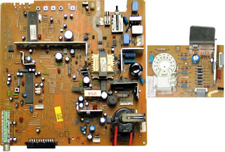
17MB55 Vestel Main Board have been used with several model LCD TVs. Toshiba, Panasonic, Philips and other popular brand TV manufacturers  uses this kit with their several models of LCD TVs.
T/T2/C/A TUNER (U119)
The Si2158 is Silicon Labs' fourth-generation hybrid TV tuner supporting all worldwide terrestrial and cable TV standards. Requiring no external balun, SAW filters, wire wound conductors or LNAs, the Si2158 offers the lowest-cost BOM for a hybrid TV tuner. Also included are an integrated power-on reset circuit and an option for single power supply operation. As with prior-generation Silicon Labs TV tuners, the Si2158 maintains very high linearity and low noise to deliver superior picture quality and a higher number of received stations when compared to other silicon tuners and discrete MOPLL-based tuners. The Si2158 also incorporates a harmonic-rejection mixer to deliver excellent Wi-Fi and LTE immunity. For the best performance with next generation digital TV standards such as DVB-T2/C2, the Si2158 delivers industry-leading phase noise performance.
Worldwide hybrid TV tuner
* Analog TV: NTSC, PAL/SECAM
* Digital TV: ATSC/QAM, DVBT2/T/C2/C, ISDB-T/C, DTMB
* 42-1002 MHz frequency range
· Industry-leading margin to A/74,NorDig, DTG, ARIB, EN55020,OpenCable™
· Lowest BOM for a hybrid TV tuner
* No balun at RF input
* Integrated tracking filters requiring no external conductors or SAW filters
* Increased ESD protection on 6 pins
· Best-in-class real-world reception
* Exceeds MOPLL-based tuners
* Lowest phase noise
* High Wi-Fi and LTE immunity
· Low power consumption
* 3.3 V and 1.8 V power supplies
* 3.3 V single-supply option
· Integrated power-on reset circuit
· Single or separate output pins for ALIF/DLIF connection to SoC
· Standard CMOS process
· 4 x 4 mm, 28-pin QFN package
· RoHS compliant.
S/S2 TUNER (U125) OPTIONAL
The RDA5815s is a fully integrated direct conversion RF front end for DVB-S,DVB-S2&ABS-S,MMDS digital satellite Reception standard CMOS process. The receiving frequency range is from 250MHz to 2150MHz, and the baseband filter’s bandwidth can be selected from 4MHz to 40MHz with 1MHz step.  The RDA5815s consists of a variable gain LNA, quadrature down converter, variable IF gain amplifiers,  variable low-pass filters, reference oscillator, VCOs, synthesizer and output baseband amplifier to drive external ADC.  Based on RDA’s some innovative technique, the rda5815s offers excellent phase noise and very low implementation loss, required for advanced modulation systems such as 8PSK and DVB-S2. This tuner RF IC
does not require a balun and its fully integrated design saves valuable board space and simplifies RF layout.
Single-Chip RF to baseband Satellite receiver
· CMOS Fully integrated RF front end
· Low noise and wide dynamic range zero IF receiver
· Input frequency range:250 to 2150 MHz
· Input signal level: -100 to 5dBm
· More than 85dB gain control range
· Fully integrated PLL
· Integrated RX VCO
· Integrated baseband LPF with selectable cut-off frequency from 4Mhz to 40Mhz with 1Mhz step
· Integrated LNA with RF AGC
· Integrated reference oscillator
· I2C bus interface
· Automatic gain control
· 0.11um RF CMOS technology
· 3V to 3.6V operations
· Power consumption of less than 600mW
· Lower profile packages 4X4mm QFN24.
T2 or S/S2 DEMODULATOR (U106) OPTIONAL
The Si216X family has 3 different IC which are pin to pin compatible. DVB-S/S2 is supported by Si2166 and DVB-T2 is supported by Si2168.
LNB SUPPLY and CONTROL IC (U108) WITH SAT OPTIONAL
Intended for analogue and digital satellite receivers/Sat-TV and Sat-PC cards, the LNBH29 series is a monolithic voltage regulator and interface IC, assembled in QFN16 (3x3) and QFN16 (4x4) specifically designed to provide the 13 / 18 V power supply and the 22 kHz tone signalling to the LNB down-converter in the antenna dish or to the multi-switch box. In this application field, it offers a complete solution with extremely low component count, low power dissipation together with a simple design and I²C standard interfacing.
This IC has a built-in DC-DC step-up converter that, from a single source from 9 V to 17.5 V, generates the voltages (VUP) that allow the linear post-regulator to work with a minimum.  Dissipated power of 0.5 W typ. @ 500 mA load (the linear post-regulator drop voltage is internally kept at VUP - VOUT = 1 V typ.). The IC is also provided with an under voltage lockout circuit that disables the whole circuit when the supplied VCC drops below a fixed threshold (4.7 V typically). The step-up converter is provided with a soft-start function which reduces the inrush current during startup. The SS time is internally fixed at 4 ms type. To switch from 0 to 13 V and 6 ms typ. to switch from 0 to 18 V.
AD87587 (U124) (OPTIONAL FOR 6W and 8W PRODUCTS)
The AD87587 is an integrated audio system solution, embedding digital audio process, power stage amplifier, and a stereo 2Vrms line driver, for driving stereo bridge-tied speakers and headphone. Using I2C digital control interface, the user can control AD87587’s input format selection, mute and volume control functions. AD87587 has many built-in protection circuits to safeguard AD87587 from connection errors. It can provide 20W output power to stereo amplifiers or 40W output power for mono applications.
Features
· 16/18/20/24-bit input with I2S, Left-alignment and Right-alignment data format
· PSNR & DR(A-weighting) Loudspeaker: 97dB (PSNR), 105dB (DR) @ 24V
· Multiple sampling frequencies (Fs)
32 kHz/ 44.1 kHz / 48 kHz and
64 kHz/ 88.2 kHz / 96 kHz and
128 kHz/176.4 kHz/192 kHz
· System clock = 64x, 128x, 256x, 384x, 512x, 768x,1024x Fs
256x~1024x Fs for 32 kHz/ 44.1 kHz / 48 kHz
128x~512x Fs for 64 kHz/ 88.2 kHz / 96 kHz
64x~256x Fs for 128 kHz/176.4 kHz/192 kHz
· Supply voltage
3.3V for digital circuit
10V~26V for loudspeaker driver
· Loudspeaker output power for Stereo@ 24V
10W x 2ch into 8_ @ 0.16% THD+N
15W x 2ch into 8_ @ 0.18% THD+N
20W x 2ch into 8_ @ 0.24% THD+N
· Sounds processing including:
Volume control (+24dB~-103dB, 0.125dB/step)
Dynamic range control
Power clipping
Channel mixing
User programmed noise gate
DC-blocking high-pass filter 1
· Anti-pop design
· Short circuit and over-temperature protection
I2C control interface with selectable device address
· Internal PLL
· LV Under-voltage shutdown and HV Under-voltage detection
· Power saving mode
· Dynamic temperature control.
DRV632 (U121) (OPTIONAL HP DRIVER FOR 2.5W PRODUCTS)
The DRV632 is a 2-VRMS pop-free stereo line driver designed to allow the removal of the output dcblocking capacitors for reduced component count and cost. The device is ideal for single-supply electronics where size and cost are critical design parameters.   The DRV632 is capable of driving 2 VRMS into a 10-kΩ load with 3.3-V supply voltage. The device has differential inputs and uses external gain-setting resistors to support a gain range of ±1 V/V to ±10 V/V, and gain can be configured individually for each channel. The DRV632 has built-in active-mute control for pop-free audio on/off control. The DRV632 has an external under voltage detector that mutes the output when the power supply is removed, ensuring a pop-free shutdown.
The DRV632 does not require a power supply greater than 3.3 V to generate its 5.6-Vpp output, nor does it require a split-rail power supply. The DRV632 integrates its own charge pump to generate a negative supply rail that provides a clean, pop-free ground-biased 2-VRMS output. The DRV632 is available in a 14-pin TSSOP.
POWER STAGE
The DC voltages required for different blocks of the main board and panel are provided by main power supply unit. MB55 chassis can operate with PW05, IPS60, IPS61, IPS70, IPS20, IPS11, IPS16, IPS17, IPS19, PW25, PW26, PW03, PW04, PW06, and PW07 as main power supply and also with 12V adaptor. The main difference from previous projects MB55 uses the 2x6 pin power connector. And only 12V_STBY supply is necessary to provide all required board supplies. As the main power board has 2x6 pin option, MB55 can operate with above given power boards. 
Which power board can be used for board to board or cable connection?
Board to board (BTB): PW05, IPS60, IPS61, IPS70, IPS11, IPS16, IPS17, IPS19
Power Cable: PW25, PW26, PW03, PW04, PW06, PW07, IPS20,
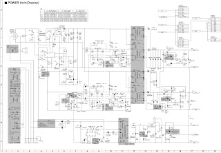
The power supplies generate 12V standby mode DC voltage and 24V system voltage only for audio IC voltage in necessary situations. Power stage which is on-chassis generates 5V, 3V3 stand by voltage and 12V, 5V, 3V3, 2.5V, 1.5V, 1.2 and 1.15V supplies for other blocks of the chassis. The power block diagram with the blocks power requirements of MB55 is given below. And also you can find below the details about the Step down IC’s and LDO’s which are used in MB55 main board.
RT7278 (U101) (3A) – RT7240 (U101) (5A)
The RT7278/RT7240 is a synchronous step down converter with Advanced Constant On-Time (ACOT) mode control. The ACOT provides a very fast transient response with few external components. The low impedance internal MOSFET supports high efficiency operation with wide input voltage range from 4.5V to 17V. The proprietary circuit of the RT7278/RT7240 enables to support all ceramic capacitors. The output voltage can be adjustable between 0.8V and 8V. The soft-start is adjustable by an external capacitor.
Features
· ACOT Mode Enables Fast Transient Response
· 4.5V to 17V Input Voltage Range
· 3A Output Current
· 60mOhm Internal Low Site N-MOSFET
· Advanced Constant On-Time Control
· Support All Ceramic Capacitors
· Up to 95% Efficiency
· 700kHz Switching Frequency
· Adjustable Output Voltage from 0.8V to 8V
· Adjustable Soft-Start
· Cycle-by-Cycle Current Limit
· Input Under Voltage Lockout
· Thermal Shutdown Protection.
MP1498 (U103 & U104) (2A)
The MP1498 is a high-frequency, synchronous, rectified, step-down, switch-mode converter with built-in internal power MOSFETs. It offers a very compact solution to achieve 2A continuous output current with excellent load and line regulation over a wide input supply range. The MP1498 has synchronous mode operation for higher efficiency over the output current load range. Current-mode operation provides a fast transient response and eases loop stabilization. Protective features include over-current protection, thermal shutdown, and external SS control.
· Wide 4.5V-to-16V Operating Input Range
· 100mΩ/40mΩ Low RDS(ON) Internal Power MOSFETs
· Proprietary Switching-Loss–Reduction Technique
· High-Efficiency Synchronous Mode Operation
· Fixed 1.4MHz Switching Frequency
· Can Synchronize to a 300kHz-to-3MHz External Clock
· Externally-Programmable Soft-Start
· OCP and Hiccup
· Thermal Shutdown
· Output Adjustable from 0.8V
· Available in an 8-pin TSOT-23 Package.
TLV70033 (U107)
The TLV700xx series of low-dropout (LDO) linear regulators are low quiescent current devices with excellent line and load transient performance. These LDOs are designed for power-sensitive applications. A precision band gap and error amplifier provides overall 2% accuracy. Low output noise, very high power supply rejection ratio (PSRR), and low dropout voltage make this series of devices ideal for most battery operated handheld equipment. All device versions have thermal shutdown and current limit for safety.
Features
· 23Very Low Dropout:
43 mV at IOUT = 50 mA, VOUT = 2.8 V
85 mV at IOUT = 100 mA, VOUT = 2.8 V
175 mV at IOUT = 200 mA, VOUT = 2.35 V
· 2% Accuracy
· Low IQ: 31 μA
· Available in Fixed-Output Voltages from 1.2 V to 4.8 V
· High PSRR: 68 dB at 1 kHz.
TLV1117LV15 (U111)
The TLV1117LV series of low-dropout (LDO) linear regulators is a low input voltage version of the popular 1117 voltage regulator. The TLV1117LV is an extremely low-power device that consumes 500 times lower quiescent current than traditional 1117 voltage regulators, making it suitable for applications that mandate very low standby current. The TLV1117LV family of LDOs is also stable with 0 mA of load current; there is no minimum load requirement, making it an ideal choice for applications where the regulator is required to power very small loads during standby in addition to large currents on the order of 1 A during normal operation. The TLV1117LV offers excellent line and load transient performance, resulting in very small magnitude undershoots and overshoots of output voltage when the load current requirement changes from less than 1 mA to more than 500 mA.
Features
· 1.5% Typical Accuracy
· Low IQ: 100 μA (max)
· 500 times lower than standard 1117 devices
· VIN: 2.0 V to 5.5 V
· Absolute maximum VIN = 6.0 V
· Stable with 0-mA Output Current
· Low Dropout: 455 mV at 1 A for VOUT = 3.3 V
· High PSRR: 65 dB at 1 kHz
· Minimum Ensured Current Limit: 1.1 A
· Stable with Cost-Effective Ceramic Capacitors:
· With 0-Ω ESR
· Thermal Shutdown and Over current Protection.
SHORT CIRCUIT PROTECTION CIRCUIT
Short circuit protection is necessary for protecting chassis and main IC against damages when any Vcc supply shorts to ground. Protect pin should be logic high while normal operation. When there is a short circuit protect pin should be logic low. After any short detection, SW forces the system to go into standby mode and to indicate short circuit detection LEDs on LED card blinked in a determined sequence.
MICROCONTROLLER – Novatek:  NT72567 (MAIN IC) (U112)
The NT72567 is an integrated digital TV system-on-chip which compliants with variety ATV as NTSC, PAL and SECAM, and DTV standards as ISDB-T, DVB-T/-C, ITU-T J.83B, integrates DTV and multi-media AV decoder, SIF demodulator, and support A/V post-processing.  The integrated video ADC and video decoder support PC VGA port, YPbPr, SCART, CVBS and S-Video Input. Regarding the tuner input, The digital VIF performs the universal analogue TV demodulation (NTSC, PAL, and SECAM), including IF processing, AGC, video demodulation, and second sound IF generation (SSIF). The video decoder supports universal TV video format. The integrated audio ADC supports stereo audio input corresponding to video input sources. The integrated TV sound decoder supports universal TV sound format.  The advanced picture quality and color engine create more vivid image impression than ever. The HDMI receiver v1.4a supports deep color, CEC features and 3D formats. The USB high speed host supports updating
firmware code, multi-media playback from the external USB flash devices.  The standby controller can operate solely from the main system, powered by the standby power source from power module, consumes as low current as possible. It meets the requirement of Green appliance.
DDR3 SDRAM K4B1G1646G 1GB G-DIE (U113)
The 1 GB DDR3 SDRAM G-die is organized as a 8Mbit x 16 I/Os x 8banks device. This synchronous device achieves high speed double-data-rate transfer rates of up to 2133Mb/sec/pin (DDR3-2133) for general applications. The chip is designed to comply with the following key DDR3 SDRAM features such as posted CAS, Programmable CWL, Internal (Self) Calibration, On Die Termination using ODT pin and Asynchronous Reset . All of the control and address inputs are synchronized with a pair of externally supplied differential clocks. Inputs are latched at the cross point of differential clocks (CK rising and CK falling). All I/Os are synchronized with a pair of bidirectional strobes (DQS and DQS) in a source synchronous fashion. The address bus is used to convey row, column, and bank address information in a RAS/CAS multiplexing style. The DDR3 device operates with a single 1.5V ± 0.075V power supply and 1.5V ± 0.075V VDDQ. The 1 GB DDR3 G-die device is available in 96ball FBGA(x16).
PANEL SUPPLY SWITCH CIRCUIT
This switch is used to open and close panel supply of TCON. It is controlled by port of main µcontroller.  Also, with this circuit, the panel power sequences could be adjusted correctly. 2 panel supply options are connected to the circuit. All of them are optional according to panels.
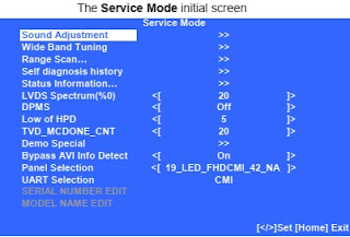
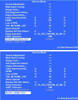
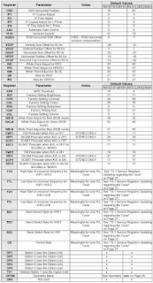
SERVICE MENU SETTINGS
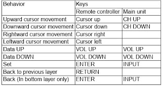
In order to reach the service menu, first press “MENU” button, then press “4725” from the remote controller keypad.
SOFTWARE UPDATE
Software update procedure can be done by following these steps below:
1. The format of the USB stick, which will be used in software update, should be in FAT32.
2. “bornova_usb_update.bin” and “bornova_usb_update.scr” files should be copied in the root directory.
3. Plug in USB stick to the TV when it is powered off.
4. Press and hold the “OK” button in the remote controller while the TV is turned off then turn on the TV.
When IR LED starts to blink, release the “OK” button and wait for installation. It may take several minutes.
This procedure finishes successfully with First Time Installation screen and then required selections will be done.
NO BACK-LIGHT PROBLEM
Problem: TV is working, IR led is OFF but there is no picture and back-light on the panel.
Possible causes: BACK-LIGHT_ON/OFF pin, DIMMING pin, back-light supply, STBY ON/OFF pin Solution: BACK-LIGHT_ON/OFF pin should be high in back-light open position. If it is low, check Q100 and panel cables.
DIMMING pin should be high or square wave in back-light open position. If it is low, please check S128 for Novatek side and panel or power cables, connectors.
For W/ADAPTOR models, back-light power supply should be in panel specs. Please check CN102 and related connectors for power supply cards.
STBY_ON/OFF should be low for standby on condition, check R104.
CI MODULE PROBLEM
Problem: CI is not working when CI module inserted.
Possible causes: Supply, supply control pin, detect pins, mechanical positions (short circuit) of pins.
Solution: CI supply should be 5V when CI module inserted. If it is not 5V  check CI_POWER_CTRL, this pin should be low.
Check mechanical positions of CI module in case a short circuit.
Detect ports should be low. If it is not low, please check CI connector pins, CI module pins and VCC_PCMCIA.
LED BLINKING PROBLEM
Problem: LED blinking, no other operation
Possible causes: A short circuit on Vcc voltages.
Solution: Protect pin should be logic high while the TV is in normal operation. When there is a short circuit, protect pin will be logic low. If you detect logic low on protect pin, unplug the TV set and control voltage points with a multimeter to find the shorted voltage to ground.
IR PROBLEM
Problem: IR or LED is not working.
Possible causes: No supply on the LED card.
Solution: Please check LED card supply.
KEYPAD OR TOUCH-PAD PROBLEM
Problem: Keypad or Touch-pad is not working.
Possible causes: No supply on the Keypad card.
Solution: Please check Keypad supply and KEYBOARD pin.
USB PROBLEMS
Problem: USB is not working or no USB Detection.
Possible causes: No supply on the USB Interface circuit.
Solution: check USB Supply, it should be nearly 5V.
NO SOUND PROBLEM AT MAIN SPEAKERS
Problem: No audio at main speaker outputs.
Possible causes: No supply voltages on VDD_AUDIO, 5V_VCC, 3V3_VCC, 12V_VCC or VDD_AUDIO_PWR.
A problem in headphone connector or headphone detect circuit.
Solution: Please check supply voltages of VDD_AUDIO, 5V_VCC, 3V3_VCC, 12V_VCC and VDD_AUDIO_PWR with a voltage-meter.  Check headphone connector and headphone detect circuit (when headphone is connected, speakers are automatically muted). Measure voltage at HP_DETECT pin, it should be 3.3v.
NO SOUND PROBLEM AT HEADPHONE
Problem: No audio at headphone output.
Possible causes: No supply voltages on 5V_VCC, 3V3_VCC or a problem in headphone connector or headphone detect pin.
Solution: Please check supply voltages of 5V_VCC, 3V3_VCC with a voltage-meter. Please check headphone connector and headphone detect pin when the headphone is plugged in. Measure voltage at HP_DETECT pin, it should be low state (0V). A headphone sign should be seen in OSD screen when volume up or down button is pressed in the remote controller.
STANDBY ON/OFF PROBLEM
Problem: Device cannot boot, TV hangs in standby mode.
Possible causes: No power supply or a problem about software.
Solution: Please check 12V_VCC, 5V_VCC and 3V3_VCC with a voltage-meter. Try to update TV with latest SW. Additionally it is good to check SW printouts via hyper-terminal (or TeraTerm). These printouts may give a clue about the problem.
DVD PROBLEM
Problem: DVD is not working.
Possible causes: A problem in Service menu or no DVD supply voltage.
Solution: Please check that DVD source is selected in Service menu. Please check supply voltage of DVD namely 12V_VCC.
NO SIGNAL PROBLEM
Problem: No signal in TV mode.
Possible causes: A problem in Service menu or no tuner supply voltage.
Solution: Please check tuner supply voltage; 3V3_TUN. Check tuner options are correctly set in Service menu.
Check AGC voltage at IF_AGC pin of tuner, it should be more than 2V.


Panasonic Microwave Oven NN-S550WF power supply and repair procedure - HV power supply schematic

$
0
0

The HV PSU measures 165mm x 105mm x 60mm and weighs 650g
At left is the control daughter board. In front of that on the main board are the opto-isolators for the control and status signals brought out to the green connector. Back left is the rectified mains filter choke.  The mains rectifier and switching transistors can just be seen on the heatsink behind the transformer.
The mains filter capacitor is at right rear. The HV rectifiers and filters (doubler) are right front – white wires are the HV output from the transformer. The green wire is for grounding the HV +ve. The two lugs at right are for connecting HV -ve and heater to the magnetron. The winding that can be seen on the transformer is the primary and is made from 3mm finely stranded wire.
Control end, High voltage end and the HV PSU
HV PSU circuit diagram
1. There is no information on the Inverter control circuit. The circuit itself is centred on one large, unmarked IC, so no help there.
2. The control and status signals seem to be a digital stream (2-3v suggests a 5V data stream).
They are opto-isolated because the majority of the circuit is at mains potential (BEWARE).
The part that isn’t is at 4kV (BEWARE)
3. The mains input side is monitored for both current and (under) voltage. No indication of what the control circuit does with this information.
4. The mains filter capacitor (C702) is very small – only 4uF. In a “normal” switching supply, there is usually 220 or 470 uF in this position.
5. Q701 that does all the hard work is a very heavy duty IGBT –  (GT60N90 - 900V @ 60 A.) Q702 forms some sort of flywheel circuit. This circuit from a Toshiba IGBT application note.
6. The HV side has a full-wave doubler rectifier and is marked 4kV @ 300mA. Unlike the classic microwave oven transformers (where one side of the winding is grounded), this means that the secondary must be well insulated from ground on both sides. A simple reconfiguration of the rectifier (replace the caps with diodes) into a bridge circuit should yield 2kV @ 600mA (depending on the diode ratings)
7. The HV filter capacitors are only 8200 pF each, effectively giving 4100pF in the doubler.  Considering that the inverter runs at about 30kHz, the reactance is equivalent to that of a 5uF capacitor at 50Hz.
8. The positive side of the HV is grounded, so it’s a –4kV supply. Don’t simply swap the ground from the positive to the negative to get a +4kV supply, as the core of the transformer is also connected to this ground trace and will suddenly rise to 4kV above ground with disastrous and potentially fatal results. Instead, reverse the polarity of the rectifier diodes to get +4kV.
A kit is available consisting of two replacements IGBT’s and a replacement capacitor. The GT60N90 has been replaced by a GT60N321 which has a 1kV rating vs. 900V. The smaller GT30J322 is unchanged, although a replacement is supplied in the kit (perhaps this is a post-blowup kit!). Also, a 330pF capacitor on the control board is replaced with a 56pF. Perhaps it would be wise to alter the value of that capacitor anyway, even if the bigger IGBT is not fitted.
Initial Measurements
Obtained the PSU from someone working in the servicing industry, so,  didn’t have a complete oven on which to do testing. So, the first challenge was to get the PSU to operate standalone. The major unknown here was the format of the control signal required to get the PSU to do anything at all. It could have been anything from a variable frequency square wave up to a complex data stream.
The only solution was to obtain a working oven, and eventually, one was obtained quite cheaply. As an added bonus, I now had a spare inverter.
With the cover off the microwave oven and CRO connected, the control and status signals were measured with the oven operating.  The Control signal turns out to be a TTL-level 220Hz square wave where the duty cycle determines the “Power” from the Magnetron.  The Status signal from the PSU is a 110Hz square wave with a fixed 50% duty cycle. This signal seems to be present when there is a current drain, probably to signal that the Magnetron is warm and operating.
The Control and Status signals are synchronised to each other, but bear no relationship to AC mains frequency or phase.  Here’s a pretty awful picture of the CRO trace showing the control signal (top) and the status signal (bottom).
The control signal duty cycles for different oven “Power” settings are shown in the table
At low power levels, the PSU starts at a higher power level (50%) until the Status signal appears, then drops back to a lower level (hence the two values in the table for On Time and Duty Cycle).  This could be because the Magnetron filament requires at least the 50% power level for it to heat up, then it sustains itself from back bombardment once RF is being produced.
At low levels, the PSU is cycled on and off at the 40% power level over a 22 second period to reduce the average power output.  Turning now to the output side of the PSU, using a 1000:1 high voltage probe on the input of the CRO shows the following waveforms. Note that the probe was not designed for use on the CRO, so the waveform could be somewhat inaccurate.
Vertical scale has 0 volts at the baseline and 1kV per division. Horizontal scale is 2mS per division.  This shows the PSU output at full power. The 100Hz ripple due to the small mains filter capacitor can clearly be seen. What is more difficult to see is the 30 kHz ripple from the inverter switching.
Although microwave ovens don’t really care if there’s ripple on the RF, it’s worth speculating why the designers allowed so much 100Hz ripple. One theory is that the Magnetron would probably stop oscillating during the low parts of the voltage cycle, allowing other users of the 2.4 GHz spectrum (e.g. WiFi networks) to get a go.
Stand-alone testing
The next step was to get the spare PSU up and running. To do this, two main things were required:
1. A circuit to generate the PWM control signal
2. A variable load, firstly to simulate a Magnetron and then to simulate a linear amplifier (the final use to which the HV Inverter supply is intended).
A simple PWM generator built using a 555. Details may be found in the 555 datasheet. The potentiometer that varies the duty cycle has fixed resistors at each end to limit the adjustment to within the 25% to 75% to range generated by the microwave oven controller.
The load is a bit more problematic. It needs to handle 4kV+ (at low loads, the output voltage might soar) at 300 mA – that’s 1200 watts. Plus, it needs to be variable for effective testing. Finally settled on using the RF deck from one of my linear amplifiers as the load. The GS-35b tube can handle up to 6kV and dissipate over 1500W (with the blower going). Also, the RF deck has a variable bias circuit so the current drain can be varied over a limited range easily.
The testing has done at each power level setting for the HV supply from minimum continuous (40%) to maximum (100%). At each setting, the RF deck bias setting was set to minimum and maximum and the voltage and current were measured for each of these.
Notes:
It is reluctant to exceed 4kV output, so, for the Minimum Load tests for 80% to 100%, the current drain is set to 300mA and voltage measured.
Working current from the HV PSU is listed as 300mA on the circuit diagram. For the Maximum Bias tests, that current was exceed by the 70% power level and the output voltage had flat-topped beyond that current, so I didn’t test at 100% power.
The initial reaction after measuring the voltage and current is that the output voltage from the HV PSU is extremely poorly regulated. However, Entered the data into a spreadsheet and calculated the power, it all became clear. The power supply is delivering constant power into the load, and doing a very good job of it. (For example, at the 50% power level, with a variation of almost 50% in current drain, the power output varies by just 1 watt.) I know little about Magnetrons, but  assume the constant power characteristic is to cope with variations in Magnetron characteristics. Regardless of whether a Magnetron operates at 3500V or 4000V, the power input (and hence heating output) will be the same.
However, the constant-power function is not very useful for powering a linear amplifier where power input varies widely (in my case, from 130 watts (idle) to 750 watts (peak)).
Required Modifications
The requirement is for 2kV @ 370mA. Therefore, the first step would be to obtain two more of the HV rectifier diodes and reconfigure the output to a bridge rectifier. The diodes must be the same type (UXC2B), which are high speed to cope with the 30 KHz switching. Of course, the diodes must also be reversed so that the negative output goes to ground.
The 100Hz ripple problem would be relatively easy to overcome. The obvious way to do this is to increase the value of the rectified mains filter capacitor. Rather than just replacing the cap (it’s a special non-polarised type), it may be better to leave the original in place in case it is also providing some special high frequency bypassing for the inverter. A 220uF capacitor can be added directly across the output of the bridge rectifier.
The 30kHz ripple would be solved in a similar manner. A standard (non-inverter) microwave oven HV filter capacitor (1uF @ 2700 VAC) would probably work OK.
Voltage regulation is the major issue. The Inverter control circuit senses the current and hence can calculate the power input to the power supply. It probably adjusts the switching duration until the current reaches the required level, according to the power setting.
There are several possible solutions
1. Regulate the output by sensing the HV output voltage and adjusting the control signal duty cycle.  Several things need to be considered here regarding the “normal” operation of the HV power supply in the microwave oven. The power output of the HV supply is never reduced below about 550 watts.  The lower power levels are achieved by cycling the 40% power level over a 22 second period. Is this because the magnetron needs a certain power level to keep the filament going or is there a problem with running the power supply below 40%? Also, the control signal is a 220 Hz square wave.
Therefore, there will be a significant delay (5+ mS) between any change in the control signal duty cycle and the HV supply responding, possibly leading to substantial spikes in the high voltage as the load changes.
2. Regulate the HV by generating an artificial current-sense signal to fool the Inverter Control Circuit into thinking that it is delivering a different power level to actual.
The comment above about minimum power level also applies here. This could be tricky to implement and, if the current-sense signal ever disappeared for any reason, the HV supply could well self-destruct as it tries to push as much power as possible into the load.
3. Use a fixed load on the power supply If a linear amplifier is required, then it could be operated in Class A. To switch off the amplifier during receive periods, the HV supply is simply turned off. Thus there is always a constant load in the power supply when it is operating.
Using a Panasonic HV Inverter power supply to power a linear amplifier has many interesting possibilities:
* Much lighter and more compact than a power supply using an iron-core transformer
* High efficiency
* 1200W of power (although continuous rating would probably be less)
* Simple control of power level
However, the constant-power characteristic of the power supply output is not compatible with the varying power load drawn by a linear amplifier, unless the amplifier is operated in Class A in which case the heat dissipation may become an issue.
Further experimentation is required for conversion of the power supply to constant voltage.

How to enter the adjustment mode – Sharp LC30HV4H LCD TV – data adjustment procedure, firmware update and details - SMPS and backlight inverter schematic

$
0
0

Sharp LC-30HV4M, Sharp LC-30HV4H - How to enter adjustment mode, adjustment procedure, firmware update and more..
Adjustment procedures (AVC system)
1.The product has been adjusted and optimised in the factory. If the product needs to be readjusted for some reason, e.g., after parts replacement, follow the instructions shown below.
2. Control parameter values set in the in-process adjustment mode has been stored in the corresponding registers. When the product is readjusted, the contents of the registers are changed. Before readjustment, factory settings should be noted in case the contents of registers require to be restored.
3. Use a stabilised AC power supply.
4. To rewrite a program, you should note the items ("OSD MENU" and "Adjustment Values") you want to change and initialise EEPROM, and then rewrite the changes into EEPROM.
How to enter the in-process adjustment mode
[Exercise great care to hide the procedure in entering the in-process adjustment mode from the customer. Inadvertent setting changes in this mode may cause a fatal error resulting in a program being unrecoverable]
Entering the in-process adjustment mode
Connect the system cable between the display and AVC system. Connect the AC cord, respectively.  An AVC System is set as a standby state, and turn off the "MAIN POWER" button of the Display.
1. Turn on the main power while holding down the "Input" button and the "VOL (-)" button of the Display simultaneously. (Be continuing pushing "INPUT" and "VOL (-)" buttons until a display comes out.)
The system will be activated.
If you see multiple lines of blue characters on the display, you are in the in-process adjustment mode. If not (the normal activation screen opens), retry.
2. Accessing the inspection process mode:
After activation of the system, make adjustments according to the instructions indicated on the process adjustment OSD menu screen.
Move to the General Process Adjustment (AVC System Section Process).
3. Restoring factory settings:
(At the time of "INDUSTRY INIT" execution, please wait for about 30 seconds until /// disappears.)
When the "INDUSTRY INIT" button is selected after activation of the system, factory channel setting remains unchanged.
After the system exits from the in-process adjustment mode.
Changes made by the user will default to factory settings. Note that channel setting is also initialised.
4. Exiting from the in-process adjustment mode
Unplug the power cable while the system is in the in-process adjustment mode to exit from the mode. Take care not to press the "POWER" button on the remote controller or the AVC system after using factory settings to run the system.
5. OSD menu screen and menu items during manual adjustment:
 The layout and menu items of the OSD menu screen may somewhat vary depending on the program versions.
 Just rewriting a program does not cause settings to be "initial values". (Preparation for adjustment)
Button operation in the in-process adjustment mode
Cursor Up
Cursor Down
Volume (Up)
Volume (Down)
ENTER
Cursor Left
Cursor Right
Channel (Up)
Channel (Down)
INPUT
Move to the next page
Back to the previous page
Increase the setting by 1
Decrease the setting by 1
Execute the function
Increase the setting by 10
Decrease the setting by 10
Move the cursor up
Move the cursor down
Change input (Tuner -> Input 1 -> Input 2 ->Input 3 -> Input 4 -> PC ->)
In-process adjustment screen layout
6. Loading the backup data and setting HDCP when the PC I/F unit is replaced
Nearly all data including factory settings, user settings, and channel setting is stored in the PC I/F unit.  The product comes with EEPROM (IC1506) on the Main Unit in case the PC I/F unit is replaced; original data backed up on the EEPROM can be loaded to the new PC I/F unit.
 How to load the backup data
Select EEPROM RECOVER in the OSD menu (page 19/19) and turn the "Volume" key ON; then press "ENTER".
 How to set HDCP
After completion of adjustments, select KEY WRITE "ON" in the OSD menu (page 1/19) for manual adjustment.
Voltage Adjustment

Tuner adjustment
PAL signal adjustment - SECAM signal adjustment
 N358 signal adjustment
Component 15k Hz signal adjustment - Component HDTV signal adjustment - Factory settings
1) Perform factory setting as the latest task. Do not turn on the power after factory setting.
2) Turn the AVC ac power off to turn off the system.
Never turn off the power during factory setting.
3) After completion of factory setting, the system will exit from the process adjustment mode automatically. If not so,
HDCP has been set to off. Check HDCP setting.
4) Factory setting results in initialisation of all user settings including channel setting.
(Items set in process adjustment mode are not initialised).
Items initialised by factory setting include the following:
 User settings (menu)
 Channel data (including broadcast frequencies)
 Password
 Operation time
 Auto installation flag
 Optimal manufacturer settings.
Adjustment Mode Menu List (AVC System)
Upgrading installed programs
Programs installed in the product are mainly divided into the following two categories:
 Main programs (for AVC system)
 Monitoring program (for display)
CAUTON: Exercise great care to hide the procedure in entering the in-process adjustment mode from the customer. Inadvertent setting changes in this mode may cause a fatal error resulting in a program being unrecoverable.
Tools required
 PC
A Windows 95/98/me/2000/XP PC that has a COM port (RS-232C).
A USB-R232C converter will be acceptable provided that it is appropriately set and has PC compatibility.
 RS-232C cross cable
Interlink cable is also acceptable.
Preparations
Rewriting a program needs the product to enter the in-process adjustment mode.
1) The rewriting software is supplied in the form of an exe file named e.g., "MAIN_2002_10_10A.exe" (provisional).
Create a directory on a HD and copy the software into the directory.
2) Double-click the file. The file will be self-extracted. Check the extracted file against the documentation accompanying with the software.
3) Connect the AVC System and the display unit with each other and make them ready for operation (make sure the power LEDs of the AVC System and display unit turn red).
4) Use an RS-232C cable to connect the PC to the AVC System.
5) Turn off the "MAIN POWER" button of the Display.
6) Press the "MAIN POWER" button while holding down the "VOL (-)" and "INPUT" buttons on the display unit simultaneously. (Be continuing pushing "VOL (-)" and "INPUT" buttons until a display comes out.)
If blue characters appear on the display, the system has entered the in-process adjustment mode successfully.
If not (the normal activation screen opens), retry.
Rewriting the main program
1) In the in-process adjustment mode, press the "CH (Up)" button on the remote controller.
2) Make sure CENTER PROG UPDATE on page 1/19 is highlighted.
(It checks that "CENTER PROG UPDATE" on page 1/19 is chosen.)
3) Use the "VOL (+)/(-)" burtons to change OFF to ON.
4) Press the "ENTER" button on the remote controller. Characters on the screen will disappear and the screen blacks out.
5) Double-click the batch file specified in the document accompanying with the software.
6) A black window (MS-DOS window) will open and rewriting starts automatically.
For a while, "ok received" will appear on the screen.
Rewiring of the main program is now complete. Unplug the AC cord from the AVC System and turn off the system and then on again.
7) Enter the in-process adjustment mode and make sure the version information on the "CENTER Version", "OSD Version" and "CVIC Version" lines on page 1/19 has been updated.
Adjustment procedures (display)
See "Adjusting mode" described above for the steps to go into adjustment process mode.
NOTE: When IC2203 is replaced, it id needed to initialisation first then Background adjustment and Common bias adjustment.
+B adjustment (LCD Control PWB: R4648)
1. Receive NTSC standard color bar signal.
2. Connect digital voltmeter to TP4602 and adjust to the specified value.
Specification: 13.00 ± 0.05V
2) Common bias adjustment
Make this adjustment each for "50 Hz", "60 Hz" and "PC". Select the input signal according to the indication onscreen.
1. Go to "Adjustment process mode".
2. On the LCD, select "14" of "PATTERN 1", dot inversion flicker pattern 2.
3. Then, select "COM BIAS" on the LCD.
4. Set the value so that the flicker on the screen is minimised.
Note: Apply this adjustment after for at least 30 min.
3) Background adjustment
1. Select video standard, and confirm the indication that the unit is preset to the standard.
2. At video input, receive the window pattern signal having left 80% WHITE (200/255) and right 20% WHITE (48/ 255).
3. Set the screen size to the full mode.
4. Go to "Adjustment process mode".
5. Adjust "R OFFSET", "G OFFSET" and "B OFFSET" in "SIL861" so that left side 80% WHITE window pattern is set to the specified value.
6. Adjust "R GAMMA", "G GAMMA" and "B GAMMA" in "SIL861" so that right side 20% WHITE window pattern is set to the specified value.
Specification: x = 0.278, y = 0.274 (80% WHITE), x= 0.259, y = 0.248 (20% WHITE) (LC-30HV4M) x = 0.283, y = 0.274 (80% WHITE), x= 0.263, y = 0.242 (20% WHITE) (LC-30HV4H)
Note: Apply this adjustment after for at least 30 min.
4) Initialisation
1. Go to "Adjustment process mode".
2. Select "1" thru "3" of "CLR MODE" in "TEST".
Setting range: 0 Normal
1 Initial setting (User clear: Factory setting)
2 Initial setting (All clear) Full initialisation of EEPROM (except for ROM area)
3 Full initialisation of Configuration EEPROM
3. Move the cursor down by one line.
4. Press "VOL UP" key and change the display from "WAIT" to "SEND" (write).
5. Do not shut down power while the display is "SEND".
6. When the writing is finished, the display changes from "SEND" to "WAIT".
5) Resetting lamp error counter
1. Go to "Adjustment process mode".
2. Select "L ERR RESET" in "TEST".
3. Reset the data to "0".
ERROR RESET
Function: Reset of fluorescent lamp error counter
It resets the times of fluorescent lamp errors and clears the last value in the memory.
Indication range: 0-5 (Fluorescent lamp errors)
(When lamp error exceeds 5 times, power supply is disabled. Resetting is required in this case.)
Adjusting Mode
1. Overview
The controller IC can be adjusted in this mode.
Adjustment is done while controlling the setting of the resistor corresponding to the selected adjustment item.
When monitor is used independently, it is adjusted using the OSD simple display function incorporated in LCD controller.
The OSD function of panel link receiver (SIL861) is used for adjustment of the independent monitor.
2. Entry to the mode
1) When cable is not connected (independent mode), follow the steps below.
a) When power switch is turned on, press the main unit INPUT and VOL DOWN keys simultaneously.
b) Press the remote controller's process adjustment key (R/C code: 40h) / process adjustment mode 2 key (R/ C code: 31h).
2) When not in independent mode, follow the steps below.
a) When power switch is turned on, press the main unit CH DOWN and VOL UP keys simultaneously.
b) Press the remote controller's process adjustment mode 2 key.
3. Exit from the mode
Turn off the power.
Press the remote controller's process adjustment mode 2 key.
4. Display
1) First layer display
The third line shows the title. The 5th line and below show the items. Microprocessor's version number appears in the 16th line.
2) Second layer display (Adjustment item display)
A single page shows up to 10 adjustment items (or 14 lines).
The third line shows the title and the screen mode selected in MODE items (only when LCD is selected).
The 5th line shows the item. Microprocessor's version number appears in the 16th line.
Example) 1.00 * 1 00
Setting is shown in decimal number.
Changing data
In "adjustment item display", the items pointed by cursor can be changed using VOL UP/DOWN key.(Holding down the key is effective.)
For the items in "LCD DATA", select the item and hit ENTER key. The ten's digit (leftmost digit) in the address changes to red (others in green). Data change using VOL UP/DOWN key is enabled.
To move to the next digit, press CH UP key (or rightward cursor key). To go back to the previous digit, press CH DOWN key (or leftward cursor key). Thus, 4 digits data can be entered.
When CH UP key is pressed while in rightmost digit, the cursor moves to the leftmost digit. When CH DOWN key is pressed while in leftmost digit, the cursor moves to the rightmost digit.
After address data adjustment, press ENTER key to exit from 4-digit adjustment and change the entire "LCD DATA" line to red letters. (Same status as item selection)
Key operation
1) Basic behaviors
Basic key behaviors are as follows
2) Data UP/DOWN
For the item for which OSD display is available, switch the display.
Adjust the data with UP/DOWN operation. (Any value beyond the limit is replaced by the limit value.)
Output data processing
Data transmission for every UP/DOWN operation (Data related to peripheral controller IC)
Execution of the last memory data when key is off
While the key is held down, the second step is performed approx. 500ms after the key operation and, after this, every single step of UP/DOWN is carried out sequentially at 135ms interval.
3) Cursor UP/DOWN
Select the adjustment item by pointing it with the cursor.
When upward cursor movement is done while the cursor is at the top item, the cursor goes to the bottom item.
(In the case of multiple pages, the cursor goes to the bottom item on the previous page.)
When downward cursor movement is done while the cursor is at the bottom item, the cursor goes to the top item. (In the case of multiple pages, the cursor goes to the top item on the next page.)
While the key is held down, the second step is performed approx. 500ms after the key operation and, after this, every single step of UP/DOWN is carried out sequentially at 135ms interval.

Inverter ground unit - schematic
Inverter unit-1 - schematic
Inverter unit-2 - schematic
SMPS (Power board) schematic

TCL L48S4700 - TCL L55S4700 – Service mode, connector socket details and software update method

$
0
0

How to enter the service mode – TCL L484700 – firmware update procedure, power, LVDS and HDMI connector details, Audio amplifier schematic
Software update
 To access the service menu
Whenever this manual asks to access the service menu, the following procedure must be performed:
- Turn on the device;
- On the remote control press the MENU button;
- Select PICTURE menu;
- Select option CONTRAST;
- On the remote control press the numerical sequence 9735;
- The service menu will be displayed.
Verification of the software version.
1) With the TV connected enter the service menu
2) In the Service menu, verify that the installed software version is correct.
MAIN SW + MBOOT SW
A - Through the user menu.
B - Save the file "MS08F6upgrade.bin" to the root of a USB device.
C - Connect the USB device, with the software, to the USB port.
D - Select MENU > OPTIONS > UPDATE SW > CONFIRM
E - Press ENTER.
F - The update will start.
[Note: The version of the Software to be used should be the one that is informed in the material plan of the respective product.]
P101 – connector pin voltages
Update when the appliance has no video
A - Save the file to the root of a USB device.
B - Leave the unit switched off (Power AC).
C - Connect the USB device, with the installation software, to the USB port
D - Press and hold the Power key of the TV and connect the TV to the power outlet.
E - The update will start.
Changing the Project ID (If panel information is wrong)
If the screen is completely dark due to the difference of panel and software installed, press 062598 + MENU + xxx
(xxx: Panel ID)
After updating, the TV will enter the TV channel mode. Enter the service menu again, select the option
Factory Reset, press enter, select yes and press enter again.
After the reset, switch the appliance off and on again using the power switch.
P101 – Main power socket voltages

HDMI socket pin details
LVDS
Audio Power Amplifier schematic


HCD-RG100 Sony mini H i-fi component system schematics, service mode and adjustments - STK433-030

$
0
0

CD section
Model Name Using Similar Mechanism - HCD-RG121
CD Mechanism Type: CDM74-K6BD80
Optical Pick-up Name: KSM-213DCP/Z-NP
Tape deck section
Model Name Using Similar Mechanism - HCD-RG121
Tape Transport Mechanism Type: CWM43FF-05
Amplifier section
AUDIO POWER SPECIFICATIONS
DIN power output (rated): 15 + 15 watts (6 ohms at 1 kHz, DIN)
Continuous RMS power output (reference):
20 + 20 watts (6 ohms at 1 kHz, 10% THD)
Music power output (reference)
40 + 40 watts (6 ohms at 1 kHz, 10% THD)
SPEAKER: accepts impedance of 6 to 16 ohms.
The laser beam on this model is concentrated so as to be focused on the disc reflective surface by the objective lens in the optical pickup block. Therefore, when checking the laser diode emission, observe from more than 30 cm away from the objective lens.
The release method of a CD disc tray LOCK function
There is a disc lock function for the disc theft prevention for a demonstration at a shop front in this machine.
Procedue:
1. Press the POWER button to turn the set on.
2. Press two buttons of STOP and (EJECT) simultaneously for five seconds.
3. The message “LOCKED” is displayed and the tray is locked.  (Even if exiting from this mode, the tray is still locked.)
4. Press two buttons of STOP and  (EJECT) simultaneously for five seconds again.
5. The message “UNLOCKED” is displayed and the tray is unlocked.
6. To exit from this mode, press the POWER button to turn the set off.
CD changer mechanism [exploded] [CD changer fittings]
[Change-over of AM Tuner Step between 9 kHz and 10 kHz]
A step of AM channels can be changed over between 9 kHz and 10 kHz.
1. Press POWER button to turn the set ON.
2. Select the function “TUNER”, and press TUNER/BAND button to select the BAND “AM”.
3. Press the POWER button to turn the set off.
4. Press TUNER/BAND and POWER buttons simultaneously, and the display of fluorescent indicator tube changes to “AM 9 k STEP” or “AM 10 k STEP”, and thus the channel step is changed over.
 [Cold Reset]
• The cold reset clears all data including preset data stored in the RAM to initial conditions. Execute this mode when returning the set to the customer.
1. Press three buttons STOP , PLAY MODE/TUNING MODE and DISC1 simultaneously.
2. The fluorescent indicator tube displays “COLD RESET” and the set is reset.
[Aging Mode]
This mode can be used for operation check of CD section and tape deck section.
• If an error occurred:
The aging operation stops and is displayed status.
• If no error occurs:
The aging operation continues repeatedly.
Operating method of Aging Mode
Turn on the main power and select “CD” of the function.
1) Set three discs in tray. Select ALL DISCS, and REPEAT OFF.
2) Load the tapes recording use into both decks.
3) Press three buttons STOP , PLAY MODE/TUNING MODE , and DISK SKIP/EX-CHANGE simultaneously.
4) Aging operations of CD and tape are started at the same time.
5) To exit the aging mode, perform [Cold Reset].
Aging mode in CD section
1) Operation during aging mode
• In the agining mode ,the program is executed in the following sequence.
(1) The disc tray opens and closes.
(2) The disc tray turns to select a disc 3.
(3) The pick-up accesses to the first track, and plays 3 seconds.
(4) The pick-up accesses to the last track, and plays 3 seconds.
(5) The disc tray opens and closes.
(6) The disc tray turns to select a disc 1.
(7) The same operation starts like step (3).
(8) After a disc 1 aging operation, a disc 2 is selected.
(9) When an aging operation of a disc 3 is completed, the display “AGING
∗∗∗∗” value increases.
(10) If no error occurs, the aging operation continues repeatedly.
Error display
Aging mode in Tape Deck section
1) Operation during aging mode
• In the aging mode, the program is executed in the following sequence.
Error display
• If error occurred, the display remains like “TAPE BAG-2”.
4. Exiting from the aging mode
• Be sure to perform Cold Reset to exit from the aging mode.
Procedure:
1. Press POWER button to turn the set ON.
2. to enter the test mode, press the three buttons STOP, PLAY MODE/TUNING MODE and ENTER simultaneously.
3. All segments and LEDs (without STANDBY LED) are turned on.
4. Press PAUSE and ENTER buttons simultaneously, and the key check mode is activated.
5. The message “KEY 0 0 0” is displayed.
Each time a button is pressed, the key code number is displayed.
6. Press PAUSE and ENTER buttons simultaneously, and the key count mode is activated.
7. The message “KEYCNT 0” is displayed.
Each time a button is pressed, “KEYCNT 0” value increased.  However, once a button is pressed, it is no longer taken into account.
8. Press PAUSE and ENTER buttons simultaneously, and the head phone detect mode is activated.
9. The message “H_P OFF” is displayed when a headphone jack is not inserted.
“H_P ON ” is displayed when a headphone jack is inserted.
10. Press PAUSE and ENTER buttons simultaneously, and the volume control detect mode is activated.
11. The message “VOLUME FLAT” is displayed.
“VOLUME UP” is displayed if rotating MASTER VOLUME knob clockwise, or “VOLUME DOWN” is displayed if rotating counterclockwise.
12. To exit from the GC test mode after the head phone detect mode, press PAUSE and ENTER buttons simultaneously.
 [Version and Destination Display Mode]
• The version or destination is displayed.
1. Press POWER button to turn the set ON.
2. To enter the test mode, press the three buttons STOP, PLAY MODE/TUNING MODE and DISC2 simultaneously.
3. The destination is displayed.
4. Press DISPLAY buttons simultaneously.
5. The version is displayed.
6. To exit from this mode, press POWER button to turn the set OFF.
Schematic [Circuit diagram]
[AMP TEST MODE]
Procedure:
1. Press POWER button to turn the set ON.
2. To enter the test mode, press the three buttons STOP, PLAY MODE/TUNING MODE and ENTER simultaneously.
3. Press the DISPLAY button.
The message “V0 0 0” “ 000” is displayed.
4. Press the GROOVE button.
The message “DBFB ON” “DBFB OFF” is displayed.
5. Press the SURROUND button.
The message “SURROUND ON” “SURROUND OFF” is displayed.
6. Press the EQ BAND button.  The message “LOW” “MID” “HIGH” is displayed.
7. Press POWER button to turn the set OFF.

[CD Service Mode]
• This mode can run the CD sled motor freely. Use this mode, for instance, when cleaning the pick-up.
Procedure:
1. Press POWER button to turn the set ON.
2. Select the function “CD”.
3. To enter the test mode, press three buttons STOP, PLAY MODE/TUNING MODE , and  EJECT simultaneously.
4. The CD service mode is selected.
5. With the CD in stop status, press >> button to move the pickup to outside track, ore press << button to inside track.
6. To exit from this mode, perform as follows:
1) Move the pick-up to the most inside track.
2) Press POWER button to turn the set OFF.
Note: • Always move the pick-up to most inside track when exiting from this mode. Otherwise, a disc will not be unloaded.
• Do not run the sled motor excessively; otherwise the gear can be chipped.
[MC Test Mode]
• This mode is used to test the function of the equalizer.
Procedure:
1. Press POWER button to turn the set ON.
2. To enter the test mode, press the three buttons STOP, PLAY MODE/TUNING MODE and DISC-3 simultaneously.
3. Press the EQ+ button.  The function of the equalizer is set to “MIN”.
4. Press the EQ– button.  The function of the equalizer is set to “MAX”
5. Press the PRESET EQ button.  The function of the equalizer is set to “EQ FLAT”.
6. MASTER VOLUME up and down.  “VOLUME MIN”, “VOLUME 16”, “VOLUME MAX” is displayed.
7. Press GROOVE button.  The message “VACS OFF” on “VACS ON” is displayed.
8. To exit from this mode, press POWER button to turn the set OFF.
 [CD Ship Mode (LOCK) ]
• This mode moves the pick-up to the position durable to vibration. Use this mode when returning the set to the customer after repair.
1. Press POWER button to turn the set ON.
2. Select the function “CD”.
5. Press the POWER button to turn the set off.
4. Press CD button and POWER button simultaneously.
5. The “STANDBY” display blinks instantaneously, and the CD ship mode is set.
[CD Ship (LOCK) & COLD RESET MODE]
Procedure:
1. Press POWER button to turn the set ON.
2. Select the function “CD”.
3. Press POWER button to turn the set OFF.
4. Press three buttons STOP, CD and DISPLAY simultaneously.
5. The “STANDBY” display blinks instantaneously and CD ship mode is set.
6. The fluorescent indicator tube displays “COLD RESET” and the set is reset.
[Disc Tray Lock]
1. Press the POWER button to turn the set ON.
2. Press two buttons of STOP & EJECT simultaneously for five seconds.
3. The message “LOCKED” is displayed and the tray is locked.  (Even if exiting from this mode, the tray is still locked.)
4. Press two buttons of STOP & EJECT simultaneously for five seconds again.
5. The message “UNLOCKED” is displayed and the tray is unlocked.
6. To exit from this mode, press the POWER button to turn the set OFF.
[CD Repeat 5 Times Limit Release Mode]
Procedure:
1. Press POWER button to turn the set ON.
2. Select the function “CD”.
3. Press three buttons STOP CD and ENTER simultaneously.
4. The message “LIMIT OFF” is displayed.
5. Press POWER button the set OFF.


How to enter service mode BBK LED LCD TV fault finding chart, SMPS schematic and more .......

$
0
0

BBK LED LCD TV 75 and 85 series service help; How to enter the service mode, fault finding chart, SMPS schematic and more ….
How to enter the Service Mode
Press “Source” button on the remote control, then press”2580”, the service menu will be displayed.
Service mode description
Color Temp: select a color temperature mode that you want to adjust;
R Gain: red gain for white balance adjusting;
G Gain: green gain for white balance adjusting;
B Gain: blue gain for white balance adjusting;
R Offset: red offset for white balance adjusting;
G Gain: green offset for white balance adjusting;
B Gain: blue offset for white balance adjusting;
Aging: to turn on or off aging mode, optional setting: On /Off;
Auto config: Auto adjust ADC channel difference, only available in VGA mode;
EEprom clear: reset EEPROM data to default value, all users’ program and setting will be lost;
Panel: select different panel for factory;
TTX language: select Teletext language, optional setting: West East Russia;
DVD source set: to turn on or off DVD source in the user menu, optional setting: On/Off;
Hotel mode: to turn on or off hotel mode, optional setting: On/Off;
Key mode:to turn on or off local keyboard, optional setting: On/Off;
Power on: to setting the power on source, optional setting: TV Other;
Power mode: to setting the power on mode, optional setting: Force on Memory standby;
Volume:to setting the max sound volume when hotel mode is active;
AGC: to setting tuner’s RF AGC value;
Notes:
Color temperature adjusting:in different source the white balance can be adjust separated.the details as below:
1) DVD&YpbPr source use same group color temperature value.
2) TV&Scart source use same group color temperature value.
3) VGA&HDMI source use separated color temperature value. Auto Config:please change source to VGA mode and with grey scale pattern then enter service mode to do this item.
Main Board Software upgrade
1.burn the software to USB device. Noted please, software name have to be MERGE182.bin.
2 Power on TV, and switch source to ATV.
3 Insert USB device to TV, then screen will display a message window to inform you upgrade TV or not. Press” LEFT” direction button to upgrade
4 It will take 40 seconds to upgrade. In this process, please don’t unplug USB device, don’t power off TV.
DVD Software upgrade
1) Rename the upgrading file to “MTK.BIN”.
2) Run“Nero Express” select burn format “ISO data disc”
3)Add “MTK.BIN” file to burn list
4)Set disc name to“1389J” then press ”burn” to start
5)After several minutes, it will display the following picture. Press “ok” to finish.
6) Enter DVD source and insert the upgrading disc to DVD loader
7) DVD begins to read the disc, Will show a dialog box.
Press “Play” button on remote control, Will shown a dialog box.
Please wait a few minutes(about 5 minutes) ,then DVD will restart auto .
During upgrading time, please don’t power off TV.
9) After TV restart, Enter DVD setup menu to check the version number.
10) Press “9” “2” “1” “0” button, You will enter DVD factory menu.
A dialog box will be showed. the version number.
SMPS PWB, circuit diagram & Troubleshooting & Connector voltages

FSE060E is a Power board+LED board ASS. Can supply 5V/3A and 12V/1.5A to system, and drive the LED backlight also.


SMPS service chart
OT2450 is a LED adaptor board, to work with FSE060E together. By configuring the circuit parameter for OT2450, so that the FSE060E output current value is used to meet the needs of a variety of panel's backlight current.
Troubleshooting chart
Main board connection details
GENERAL DESCRIPTION
00K104 is a control board of DVD. It supports DVD loaders which are produced by HuaYang It can control a LCD TV(Built-in DVD) with TV control board
00K104 includes audio output such as 2CH and SPDIF
00K104 provides extended functions such as USB2.0 FULL SPEED.

Sharp LCD TV T’Con board faults. No screen, Distorted screen, vertical lines

$
0
0
Sharp T-con Board: X3219TPZ - LCD Panel Model: 37 inches – No display, display distortion
Used with Insignia LS-LCDTV32, Toshiba 26WL46B and Sharp 32 inch LCD TVs
* MOSFET. If this component failure, it will cause the TV No Display.
* IC1= KZ4E167212. If this IC failure, it will cause the TV No Display.
* IC200= 1H04627 power management IC. If this IC failure, it will cause the TV No Display.
* IC2 & IC3= SDRAM memory IC. If this IC failure, it will cause the TV No Display or Display Distortion problem.
Sharp T-con Board: CPWBX3255TPZ - LCD Panel Model: 32 Inches, 37 Inches - Vcc input= 5V – No display fault
Used with Sharp LD 26SH3U, Sharp 32LX500
* IC501= ADD8707 Gamma IC. If this IC failure, it will cause the TV No Display.
* IC600= LZ9FB27. If this IC failure, it will cause the TV No Display.
* IC201= THV1031 power management IC (DC-DC circuit IC). If this IC failure, it will cause the TV No Display.
* IC1= T3Z16AGF. If this IC failure, it will cause the TV No Display or Full Screen of Colorful Vertical Lines/Bars.
T-con Board: CPWBX3749TP - LCD Panel Model: 52 inches- No display, full screen vertical lines or bars.
Used with Sharp 52MF437S/37, Philips 52PFL5432/78, Philips 52PFL7762D, Philips BDL4631V/00, LG 50LG50FD and more models
* IC28= BD8133FV Gamma IC. If this IC failure, it will cause the TV No Display or Full Screen of Vertical Lines/Bars.
* IC7= THV3051 power management IC. If this IC failure, it will cause the TV No Display.
* IC1 & IC2= T3Z18AFG IC. If this IC failure, it will cause the TV No Display.
* IC30= TB730A5 IC. If this IC failure, it will cause the TV No Display.
Sharp T-con Board: X3562TP ZE - Vcc input= 5V – No display, Full white screen, Vertical lines/bars
Used with Sharp LC32GA8E, Sharp LC32AD5E-BK, Sharp LC32AV22U and many other models
* IC4= EEPROM memory IC. If this IC failure, it will cause the TV No Display or White Screen.
* IC1= T3Z18AGF. If this IC failure, it will cause the TV No Display or Full Screen of Vertical Lines/Bars.
* FET4= A2706. If this component failure, it will cause the TV No Display.
* IC6= THV3051 power management IC (DC-DC circuit IC). If this IC failure, it will cause the TV No Display.
* BD8139EFV Gamma IC. If this IC failure, it will cause the TV No Display.

UE32ES5500, UE26EH4500 – Samsung LCD TV – firmware update, troubleshooting, PIN reset, calibration and more

$
0
0

Samsung X10+ LED TV - UE32ES5500(5700), UE40ES5500(5700), UE46ES5500(5700)
UE32EH5300, UE40EH5300, UE46EH5300, UE26EH4500, UE22ES5400 
ES5700 : DVB-T/C/S2 Model
When you want to initialize the TV setting, use the 'reset' menu. Initial PIN number : '0-0-0-0
(If you want change the PIN number, use the Change PIN function located 'System-Security' menu.)
After you execute 'Reset' function, All the settings will return to factory default.
If you forget the PIN code, press the remote control buttons in the following sequence in Standby mode, which resets the PIN to 0,0,0,0:
[MUTE 8,2,4, Power ON.]
How to check the SW version
Use the main menu
 Click the "menu" key in remote controller.
 Select Support menu.
 Locate the menu cursor "Software Upgrade" menu.
 Click the "info" key.
 Check the Main SW and SubMicom SW Version.
How to Upgade Main SW and Micom
Insert the USB device containing the firmware upgrade downloaded from Samsung.com into TV.  Be careful not to disconnect the power or the USB drive while upgrades are being applied.  The TV will turn off and turn on automatically after completing the firmware upgrade.  Check the firmware version after the upgrade are complete [the new version will have higher number than the older version].  When the software is upgraded, video and audio setting you have made will return to their default [factory] settings.  It is recommended you to write down your settings before the beginning of the firmware update.  After update is completed, restore the previous settings.
How to Upgrade Main SW
Store the SW program named –T-MST10PDEUC” in USB memory stick.
Connect the USB
Click the Menu key in remote control.
Select Support Menu
Locate the menu cursor :Software Upgrade” menu.
Click the Enter key.
How to Upgrade SubMicom SW
Store the SW program named “SubmicomEU_10***” in USB memory stick.
Connect the USB.
Enter the factory.
Locate the cursor “SVC” menu.
Click Enter key.
Locate the cursor ‘SUBMICOM UPGRADE” menu.
Click on the pictures to magnify
Troubleshooting

This Troubleshooting is based on E5500(5700) Model.

No Power – troubleshooting table and possible fault locations

No video  HDMI 1, 2, 3 – Digital signal – troubleshooting table &  possible fault locations
No video – Tuner_CVBS – Troubleshooting and possible fault  locations
No video – Tuner DTV – troubleshooting and fault locations
No video AV – troubleshooting and fault locations
No video – Component – troubleshooting and fault locations
No sound – Speaker, Headphone out, Optical – troubleshooting and fault locations
Calibration


How to troubleshoot LG 43LH60 series LED TVs - Universal remote control set-up codes

$
0
0

LG 43LH60** -ZA/ZB/ZF, 43LH615V 43LH615V-ZE  LED TV - CHASSIS : LD66H
DTV (MPEG2/4, DVB-T) : 26 countries
Germany, Netherlands, Switzerland, Hungary, Austria, Slovenia, Bulgaria, France, Spain, Belgium, Luxembourg, Greece, Czech, Turkey, Morocco, Ireland, Latvia, Estonia, Lithuania, Poland, Portugal, Romania, Albania, Bosnia, Slovakia, Belarus.
DTV (MPEG2/4, DVB-T2) :11 countries
UK(Ireland), Sweden, Denmark, Finland, Norway, Ukraine, Kazakhstan, Russia, Italy, Croatia, Serbia.
DTV (MPEG2/4, DVB-C) : 37 countries
Germany, Netherlands, Switzerland, Hungary, Austria, Slovenia, Bulgaria, France, Spain, Italy, Belgium, Russia, Luxembourg, Greece, Czech, Croatia, Turkey, Morocco, Ireland, Latvia, Estonia, Lithuania, Poland, Portugal, Romania, Albania, Bosnia, Serbia, Slovakia, Belarus, UK, Sweden, Denmark, Finland, Norway, Ukraine, Kazakhstan.
DTV (MPEG2/4,DVB-S) : 37 countries
Germany, Netherlands, Switzerland, Hungary, Austria, Slovenia, Bulgaria, France, Spain, Belgium, Luxembourg, Greece, Czech, Turkey, Morocco, Ireland, Latvia, Estonia, Lithuania, Poland, Portugal, Romania, Albania, Bosnia, Slovakia, Belarus, UK(Ireland), Sweden, Denmark, Finland, Norway, Ukraine, Kazakhstan, Russia, Italy, Croatia, Serbia.
Supported satellite : 35 satellites
ABS1 75.0E, AMOS 4.0W, ASIASAT3S 105.5E, ASTRA 19.2E, ASTRA 23.5E, ASTRA 28.2E, ASTRA 4.8E, ATLANTIC BIRD2 8.0W, ATLANTIC BIRD3 5.0W, BADR 26.0E, DIRECTV-1R 56.0E, EUROBIRD 9A 9.0E, EUROBIRD3 33.0E, EUTELSAT 36 A/B 36.0E,EUTELSAT W2A 10.0E, EUTELSAT W3A 7.0E, EUTELSAT7WA 7.3WEUTELSAT 16.0E, EXPRESS AM1 40.0E, EXPRESS AM3 140.0E, EXPRESS AM33 96.5E, HELLASSAT 39.0E, HISPASAT 1CDE 30.0WHOTBIRD 13.0E, INTEL SAT10&7 68.5E, INTELSAT15 85.2E, INTELSAT1R 50.0W, INTEL SAT903 33.5W, INTELSAT904 60.0E, NILESAT 7.0W, NSS12 57.0E, THOR 0.8W, TURKSAT 42.0E,YAMAL201 90.0E, OTHER
4 System : PAL, SECAM, NTSC4.43, PAL60 Hybrid Type.
USB Software download
(1) Put the USB Stick to the USB socket.
(2) Automatically detecting update file in USB Stick
- If your downloaded program version in USB Stick is Lower, it didn’t work. But your downloaded version is Higher, USB data is automatically detecting (Download Version High & Power only mode, Set is automatically Download)
(3) Show the message “Copying files from memory”.
(4) Updating is starting.
(5) Updating completed, the TV will restart automatically.
(6) If your TV is turned on, check your updated version and Tool option. (Explain the Tool option, next stage)
* If downloading version is more high than your TV have, TV can lost all channel data. In this case, you have to channel recover. if all channel data is cleared, you didn’t have a DTV/ATV test on production line.
* After downloading, have to adjust Tool Option again.
(1) Push "IN-START" key in service remote control.
(2) Select "Tool Option 1" and push "OK" key.
(3) Punch in the number. (Each model has their number)
Disassembly: Back Cover.
Repair Procedure.
First of all, Check whether all of cables between board is inserted properly or not.  (Main Board, Power B/D, LVDS Cable, Speaker Cable, IR B/D Cable)
Video error - No video/Normal audio - Check back light with naked eye
After turning on the power and disassembling the case, check with the naked eye, whether you can see light from locations.
Check White Balance value
Entry method
1. Press the ADJ button on the remote control for adjustment.
2. Enter into White Balance of item 13.
3. After recording the R, G, B (GAIN, Cut) value of Color Temp (Cool/Medium/Warm), re-enter the value after replacing the MAIN BOARD.
Video error_Video error, video lag/stop
TUNER input signal strength checking method
All Settings > Channels > Channel Tuning > Manual Tuning > Select Channel
Signal Strength is too strong : Use attenuator (-10dB, -15dB, -20dB etc.)
Signal Strength is too weak : Use Signal Booster.
Version checking method
Press the IN-START with the remote control for adjustment. (Service Remote Control)
Video error_Video error, video lag/stop - TUNER checking.
1. Check the signal strength or check whether the screen is normal when the external device is connected.
2. After measuring each voltage from power supply, finally replace the Main Board.
Video error _Vertical/Horizontal bar, residual image, light spot.
As the part connecting to the external input, check the screen condition by signal.
Check the contact condition of the Link Cable, especially dust or mis-insertion.
Module faults.  No repair, Exchange the display module. These symptoms are common for all LCD screens, irrespective of its brand or screen size.
Power error _Off when on, off whiling viewing - POWER OFF MODE checking method.
Press the IN-START button of the remote control for adjustment.
Check the entry into adjustment item 3.
Audio error_No audio/Normal video. Checking method in menu when there is no audio.
1. Press the Setting button on the remote control
2. Select the Sound function of the Menu
3. Select the Sound Out
4. Select TV Speaker.
Check Main B/D 13V
Check Power B/D 13V
After connect speaker and contact the output terminal of the speaker with GND, if there is sound output noise, we conclude the speaker works well.
Function error - Remote control operation checking method
1. Check IR cable condition between IR & Main board.
2. Check the standby 3.5V on the pin 18.
Wi-Fi operation checking method
1. Check the IR cable condition
2. Check the WiFi Cable condition
3. Check the voltage 3.4V_WIFI on P4101.
Universal remote control set-up codes for LG & Goldstar
0011 0025 0049 0050 0054 0055 0101 0107 0110 0119 0152 0165 0166 0168 0181 0182 0195 0235 0250 0303 0379 0380 0414 0421 0433 0460 0465 0611 0613 0658

How to enter the service mode – Pioneer VSX821, VSX521, adjustments, error codes, amp schematic

$
0
0

Pioneer VSX-821-K, VSX-921-K, VSX-521-K AUDIO/VIDEO MULTI-CHANNEL RECEIVER - Error codes, service mode, adjustments, firmware update, Amp-circuit diagram and more
Service mode
The numbers of detections for various protection processes are displayed.
How to enter/exit
During Standby mode, simultaneously press and hold the [PRESET –] and [STANDBY/ON] keys for 2 seconds to enter this mode.
The display will return to the normal indication when no key operation is performed for 5 seconds.
Display mode is available only when the product operates properly.
If any protection function is activated while the product is in use, the product cannot be turned ON and enter the Display mode. In such a case, cancel the protection function, simultaneously holding the [ADVANCD SURROUND] and [STANDBY/ON] keys on the front panel pressed for 2 seconds will cancel Key Input Inhibition mode after a DC error detection and turn the unit ON  to cancel the status after detection of the DC error." If a protection function is activated immediately after the previous protection function is canceled, cancel that protection function again then enter STBY mode immediately. You can then see the error logs, following the above procedures, until a next protection function is activated.
Service mode display and details
Setting and adjustment: adjustment required when the unit is repaired or replaced
When any of the following assemblies is replaced
AMP Assy > "8.3 IDLE CURRENT ADJUSTMENT" (All channel)
Other assemblies > No adjustment required.
Idle current adjustment: VSX-821-K, VSX-521
 When any component parts which are within the red square on the following circuit diagram are replaced, the idle current adjustment of that channel is required. (Idle current adjustment for another channel is not required.)
However, when any capacitors are replaced, the adjustment is not required.
(The following circuit diagram is for SL channel, but another channel also has same circuit diagram and same adjustment is required).


VSX-921-K
Firmware update: Necessary Tools
*PC with a serial port
*RS-232C cable (9-pin to 9-pin, straight cable)
*RS-232C UPDATE jig: GGF1642 (Use FFC of GGF1642. (10P to 10P FFC))
*Firmware
Connections
MAIN and SUB microcomputers update
Check to the software VER of MAIN & Sub microcomputers.
Make sure that the main unit is in STANDBY mode.
Press and hold the "ENTER" and "STANDBY/ON" keys, then press the "ENTER" key to display each UCOM version.
Each time the "ENTER" key is pressed, and then indications on the FL display change as follows:
Schematic diagram:  audio assy
AMP ASSY (1/2) (for VSX-921-K)
AMP ASSY (2/2) (for VSX-921-K)
How to Update the USB Microcomputer (VSX-821-K, VSX-921-K ONLY)
1. Copy the "VSX_USB.rom" file to the root directory of a USB memory device.
2. Press the iPod USB key on the remote control unit to select iPod/USB function then connect the USB memory device.
3. After accessing the USB memory device, "UPG? NO" is displayed on the FL display and "UPDATE? NO" is displayed as
an On-Screen display.
4. Press the iPod USB key on the remote control unit.
5. Send either iPod/USB Cursor Left or iPod/USB Cursor Right code.
6. "UPG? YES" is displayed on the FL display and "UPDATE? YES" is displayed as an On-Screen display.
7. After sending the iPod/USB Enter code, updating starts. (“UPDATE” is displayed on the FL display.)
8. When "UPG? NO" is displayed on the FL display and "UPDATE? NO" is displayed as the On-Screen display, updating is
completed.
9. Disconnect the USB memory device then turn the unit off.
[Procedures]
(3) How to update the DSP Microcomputer
1. Select an Input Function that allows reception via Optical input 1 or 2 then set the unit to STBY_Off mode.
2. Press the SPEAKERS and STANDBY/ON keys simultaneously to enter DSP UpDate mode. ("DSP UP" is displayed.)
3. When "PLAY" is displayed, playback of the .wav file starts. (Play the file only once. NEVER repeat playback.)
("PLAY" is displayed.)
4. After playback is finished and "ENTER" is displayed, press the ENTER key on the front panel. ("ENTER" is displayed.)
5. "WRITING" is automatically displayed.
6. After writing is completed, "COMPLETE" is displayed.
7. Turn the unit off then confirm that the version has been updated.
[How to Confirm the Version of the USB Microcomputer]
1. Select the iPod/USB function then turn the unit off.
2. While holding the ENTER key on the front panel pressed, press the STNADBY/ON key.
3. When the receiver is turned on, press the ENTER key on the main unit three times.
(Each time the ENTER key is pressed, the indications on the FL display change as follows:
Main -> Sub -> DSP -> USB -> All segments lit.)
4. The version is displayed on the FL display, as "USB:***."
Notes on updating
* If you perform updating of the same software twice, it may fail.
* If the indication "UPDATE" on the FL display does not change, let it sit for a few minutes.
If the indication on the FL display changes to one other than "UPDATE," the unit becomes operable.
Turn the unit off after it becomes operable.

DELL 2005FPW 20 inch LCD color monitor, How to enter service mode, disassembly, schematic diagram, troubleshooting chart

$
0
0
How to disassemble, hot to upgrade, EDID data download, Troubleshooting, circuit diagram - DELL 2005FPW-20 inch LCD colour monitor
Disassembly
* Remove the screws.
** Lift central inside edge of Cabinet upward with fingertip then latch will be departed.  (This time take care so that do not give damage on the module surface.)
*** Progress to left and lifts cabinet furtively and extracts latch.
**** Progress to right and extracts cabinet side latch by same method.
****** Progress to bottom. 
Warning : if you lift cabinet up, power connector lead may be disconnected or damaged.)  Refer to the small picture.
******* Turn upside down then lift the back cover ass'y up.
Video Controller Part & Display Data Transmitter Part.
This part amplifies the level of video signal for the digital conversion and converts from the analogue video signal to the digital video signal using a pixel clock.
The pixel clock for each mode is generated by the PLL.
The range of the pixel clock is from 25MHz to 147MHz.
This part consists of the Scaler, Flash-ROM IC which stores program data, Reset IC.
The Scaler gets the video signal converted analog to digital, interpolates input to 1680 x1050 resolution signal and outputs 8-bit R, G, B signal to transmitter.
Especially pre-amp / ADC / Video controller/ Transmitter are merged to one chip "Gm1501" by Genesis.
This part transmit digital signal from the Scaler to the receiver of module’s.
Power Part
This part consists of the two 3.3V and one 2.5V and one 1.8Vregulators to convert power which is provided
12V in Power Board V is provided for LCD Panel.(Only LPL)
5V in Power Board V is provided for LCD Panel.(Only AUO)
12V in Power Board V is provided for Inverter Part.
Also, 5V is converted 3.3V and 2.5V and 1.8V by regulator. Converted power is provided for IC in the main board.
Operation description (Power)
1. EMI components.
This part contains of EMI components to comply with global marketing EMI standards like FCC,VCCI CISPR, the circuit included a line-filter, across line capacitor and of course the primary protection fuse.
2. Input rectifier and filter.
This part function is for transfer the input AC voltage to a DC voltage through a bridge rectifier and a bulk capacitor.
3. Energy Transfer.
This part function is for transfer the primary energy to secondary through a power transformer.
4. Output rectifier and filter.
This part function is to make a pulse width modulation control and to provide the driver signal to power switch, to adjust the duty cycle during different AC input and output loading condition to achieve the dc output stabilized, and also the over power protection is also monitor by this part.
5. Photo-Coupler isolation.
This part function is to feed back the dc output changing status through a photo transistor to primary controller to achieve the stabilized dc output voltage.
6. Signal collection.
This part function is to collect the any change from the dc output and feed back to the primary through photo transistor
7. Inverter
The inverter converts from DC12V to AC 840Vrms and operate back-light lamp of module.
Adjustments
Windows EDID V1.0 User Manual
Operating System: MS Windows 98, 2000, XP
Port Setup: Windows 98 > don’t need setup
Windows 2000, XP > Need to Port Setup.
This program is available to LCD Monitor only.
Port Setup
a) Copy “UserPort.sys” file to “c:\WINNT\system32\drivers” folder
b) Run Userport.exe.
c) Remove all default number
d) Add 300-3FF
e) Click Start button.
f) Click Exit button.
EDID Read & Write
1) Run WinEDID.exe
Edit Week of Manufacture, Year of Manufacture, Serial Number.
a) Input User Info Data
b) Click “Update” button
c) Click “Write” button
Service mode
1. Turn off the power switch at the front side of the display.
2) Wait for about 5 seconds and press MENU, PLUS, POWER key.

3) The SVC OSD menu contains additional menus that the User OSD menu as described below.
a) WB Adjust: To adjust ADC cutoff/gain.
Use Black pattern for cutoff adjustment and press Menu. If the number changes to 1, cutoff adjustment is OK.
Use full white pattern for gain adjustment and press Menu. If the number changes to 2, gain adjustment is ok.
b) NVRAM Init : EEPROM initialise (24C16).
c) Reset Time : Reset elapsed time.
d) Aging: Select Aging mode (On/Off).
e) WProtect : To enable write protection.(24c02)
f) Blue : Allows you to set the R/G/B - 9300K value manually.
g) Red: Allows you to set the R/G/B - 5700K value manually.
h) Normal: Allows you to set the R/G/B - 6500K value manually.


Cable Connection
Troubleshooting chart
Schematic 

LG 32LF520D LED TV – SMPS schematic, troubleshooting, firmware update procedure and more

$
0
0

North/Latin America, Europe/Africa, Asia/Oceania Models
IC Remove/Replacement
Some chassis circuit boards have slotted holes (oblong) through which the IC leads are inserted and then bent flat against the circuit foil. When holes are the slotted type. When working with boards using the familiar round hole, use the standard technique.
Circuit Board Foil Repair
Excessive heat applied to the copper foil of any printed circuit board will weaken the adhesive that bonds the foil to the circuit board causing the foil to separate from or "lift-off" the board. The following guidelines and procedures should be followed whenever this condition is encountered.
Adjustments
(1) The adjustment is according to the order which is designated and which must be followed, according to the plan which can be changed only on agreeing.
(2) Power adjustment: Free Voltage.
(3) Magnetic Field Condition: Nil.
(4) Input signal Unit: Product Specification Standard.
(5) Reserve after operation: Above 5 Minutes (Heat Run)
Temperature : at 25 °C ± 5 °C
Relative humidity : 65 ± 10 %
Input voltage : 100-220 V~, 50/60 Hz
(6) Adjustment equipment
: Color Analyzer(CA-210 or CA-110), Service remote control.
USB DOWNLOAD(*.prg file download)
(1) Make sure USB disk format is FAT32.
(2) Copy "MBOOT_AS_*.prg"(for Mboot updated if need) and "UPDATE_A71_INIT_PAD_*.prg" two files to root of USB disk.
(3) Insert USB disk to USB slot.  (if no need to update Mboot, jump to step 7 directly)
(4) AC OFF > ON
(5) TV set will display like as this photo. It will take around 10 sec. wait for 100%.
(6) Keep USB disk in USB solt.
(7) AC OFF > ON
(8) TV set will display like these.
(9) Wait for display "100%"
(10) AC Off.
(11) Unplug USB disk.
(12) AC On.
(13) Check firmware version : 2.00(for example)
When you finish initialization setting, you can check firmware version on Factory Menu Switch to AV input source, press "Left" key > 7 > 9 > "OK" key to enter Factory Mode.
(14) Select a country : GHANA (for example)
Go to "Ship To" and use "Left", "Right" to select country and press "OK", TV should be turn Off.
(15) After turn on again, Check selected country : GHANA (for example)
Press "Right"> "EXIT"> "OK" to go to Engineering Information menu.
ADC Process
Enter Factory mode.
The screen will show as below, select Source Calibration and pushing enter key.
After pushing the right key, this function will be implement and show OK on screen button side as below.
Only Component is requested calibration.
The timing: 1080i/60Hz,
Manual W/B process using adjusts Remote control.
* Color analyzer( CA210) should be used in the calibrated ch by CS-2000.
* Operate the zero-calibration of the CA-210, then stick sensor to the module when adjusting.
* After enter M Mode by pushing up or down key to select “Cool”, ,
* Press “enter” key to enter the item.
* For manual adjustment, it is also possible by the following sequence.  (1) Set TV in M mode using learning remote controller and then operate heat run longer than 15 minutes. (If not executed this step, the condition for W/B may be different.)
(2) Zero Calibrate the probe of Color Analyzer, then place it on the center of LCD module within 10 cm of the surface (3) Select each items (Red/Green/Blue Gain) using / (CH +/-) key on Remote control.
(4) Adjust R/ G/ B Gain using /(VOL +/-) key on R/C.
(5) Adjust three modes all (Cool / Medium / Warm)
- For G-FIX model
Cool Mode
1) Fix the G gain to 132 (default data) and decrease the others.
2) Adjust B Gain to set y in spec.
3) Adjust R Gain to set x in spec.
Medium / Warm Mode - Fix G gain to 132 (default data) and adjust the others.
(6) When adjustment is completed, exit adjustment mode using EXIT key on Remote control.
CASE Cool
First adjust the coordinate far away from the target value(x, y).
1) x, y > target
i) Decrease the R, B.
2) x, y < target
i) First decrease the B gain,
ii) Decrease the one of the others.
3) x > target, y < target
i) First decrease B, so make y a little more than the target.
ii) Adjust x value by decreasing the R.
4) x < target, y > target
i) First decrease B, so make x a little more than the target.
ii) Adjust x value by decreasing the R.
* After you finish all adjustments unplug the AC cable.
SMPS & LED driver schematics
Troubleshooting procedure

How to enter service mode to Panasonic TX42G30J Plasma TV, LED blinking codes and other service adjustments

$
0
0

Panasonic Plasma TV - TX-P42G30E, TX-P42G30J, TX-PF42G30 [GPF14D-E Chassis]
Replacement of ICs:
When Peaks IC (IC8000) is replaced, EEPROM (IC8902) should be also replaced with new one the same time.
When EEPROM (IC8902) is replaced, Peaks IC (IC8000) is not necessary to be replaced the same time.
After the replacement of IC, SELF CHECK should be done to generate the final KEY data.
How to SELF CHECK: While pressing [
VOLUME ( - )] button on the main unit, press [MENU] button on the remote control for more than 3 seconds.
TV will be forced to the factory shipment setting after this SELF CHECK.
How to enter into Service Mode
While pressing [VOLUME ( - )]button of the main unit, press [0] button of the remote control three times within 2 seconds.
Key command
[1] button...Main items Selection in forward direction
[2] button...Main items Selection in reverse direction
[3] button...Sub items Selection in forward direction
[4] button...Sub items Selection in reverse direction
[RED] button...All Sub items Selection in reverse direction
[GREEN] button...All Sub items Selection in forward direction
[VOL] button...Value of sub items change in forward direction ( + ), in reverse direction ( - )
To EXIT, Switch off the power with the [POWER] button on the main unit or the [POWER] button on the remote control.
Contents of adjustment mode
• Value is shown as a hexadecimal number.
• Preset value differs depending on models.
• After entering the adjustment mode, take note of the value in each item before starting adjustment.
Option - Mirror
Picture can be reversed left and right or up and down.
00 : Default (Normal picture is displayed)
01 : Picture is reversed left and right.
02 : Picture is reversed up and down.
[If the defective symptom (e.g. Vertical bar or Horizontal bar) is moved by selection of this mirror, the possible cause is in A-board]
Service Tool mode
1. Select [SRV-TOOL] in Service Mode.
2. Press [OK] button on the remote control.
Display of SOS History
SOS History (Number of LED blinking) indication.
From left side; Last SOS, before Last, three occurrence before, 2nd occurrence after shipment, 1st occurrence after shipment.
This indication will be cleared by [Self-check indication and forced to factory shipment setting].
POWER ON Time, On/Off
Note : To display TIME/COUNT menu, highlight position, then press MUTE for 3 sec.
Time : Cumulative power on time, indicated hour : minute by decimal
On/Off : Number of On/Off switching by decimal
Note : This indication will not be cleared by either of the self-checks or any other command.
Exit
1. Disconnect the AC cord from wall outlet or switch off the power with [ Power ] button on the main unit.
Hotel mode
To Restrict a function for hotels.
Access command to the Hotel mode setup menu
In order to display the Hotel mode setup menu:
While pressing [VOLUME (-)] button of the main unit, press [AV] button of the remote control three times within 2 seconds.
To exit the Hotel mode setup menu
Disconnect AC power cord from wall outlet.
Data Copy by SD Card
Board replacement (Copy the data when exchanging A-board):
When exchanging A-board, the data in original A-board can be copied to SD card and then copy to new A-board.
(b) Hotel (Copy the data when installing a number of units in hotel or any facility):
When installing a number of units in hotel or any facility, the data in master TV can be copied to SD card and then copy to other TVs
Make pwd file as startup file for (a) or (b) in a empty SD card.
1. Insert a empty SD card to your PC.
2. Right-click a blank area in a SD card window, point to New, and then click text document. A new file is created by default (New Text Document.txt).
3. Right-click the new text document that you just created and select rename, and then change the name and extension of the file to the following file name for (a) or (b) and press ENTER.
File name:
(a) For Board replacement : boardreplace.pwd
(b) For Hotel : hotel.pwd
Note:
Please make only one file to prevent the operation error.
No any other file should not be in SD card.
Data copy from TV set to SD Card
1. Turn on the TV set.
2. Insert SD card with a startup file (pwd file) to SD slot.  On-screen Display will be appeared according to the startup file automatically.
3. Input a following password for (a) or (b) by using remote control.
(a) For Board replacement: 2770
(b) For Hotel : 4850
Data will be copied from TV set to SD card.
It takes around 2 to 6 minutes maximum for copying.
4. After the completion of copying to SD card, remove SD card from TV set.
5. Turn off the TV set.
Note:
Following new folder will be created in SD card for data from TV set.
(a) For Board replacement: user_setup
(b) For Hotel : hotel
Data copy from SD Card to TV set
1. Turn on the TV set.
2. Insert SD card with Data to SD slot.  On-screen Display will be appeared according to the Data folder automatically.
3. Input a following password for (a) or (b) by using remote control.
(a) For Board replacement: 2771
(b) For Hotel : 4851
Data will be copied from SD card to TV set.
4. After the completion of copying to SD card, remove SD card from TV set.
(a) For Board replacement: Data will be deleted after copying (Limited one copy).
(b) For Hotel : Data will not be deleted and can be used for other TVs.
5. Turn off the TV set.
Note:
1. Depending on the failure of boards, function of Data copy for board replacement does not work.
2. This function can be effective among the same model numbers.
Check of the IIC bus lines
Produce TV reception screen, and while pressing [VOLUME ( - )] button on the main unit, press [OK] button on the remote control for more than 3 seconds.
Self-check indication and forced to factory shipment setting:
Caution:
New key will be generated and previous TV programmes recorded in USB HDD will not be viewed.
Produce TV reception screen, and while pressing [VOLUME ( - )] button on the main unit, press [MENU] button on the remote control for more than 3 seconds.
Exit
Disconnect the AC cord from wall outlet or switch off the power with [ Power ] button on the main unit.
Power LED blinking timing chart
Information of LED Flashing timing chart.
When an abnormality has occurred the unit, the protection circuit operates and reset to the standby mode. At this time, the
defective block can be identified by the number of blinks of the Power LED on the front panel of the unit.

Philips 43PFH4082-96 How to enter the service mode, software update, SMPS schematic

$
0
0

How to remove the stand and the back cover – Philips 43PFH4082 – 43 inch LCD TV, firmware update, power schematic
How to remove the stand, and the back cover
Remove the fixation screws [1] that secure the stand 2. Take the stand bracket out from the set.
How to remove the back cover
1. Use electric screwdriver to dismantle 7PCS Ф3×6mm screws from back cover.
2. Put removed screws at appointed material box. Do not mix it with others material
3. After self-check OK, flow it into next station by foot switch.
Disassemble Back Cover-2
1. Take off screws with electric screwdriver.
2. Categorise and place removed screws at the appointed material box. Do not mix with other material.
3. Both hands respectively grasp the middle of left and right sides of back cover-M, lift the right side of back cover to separate the buckle on lower right side of back cover-M, from back cover-L. Then Pushing back cover-M toward right and up to make the buckle on the lower left side of back cover-M separate from back cover-R. Take out power cord from the slot and then take down back cover-M and put it on the mat of circulated cart.
4. After self-check OK, flow it into next station by foot switch.
Disassemble Wire
Use diagonal pliers to cut off 2pcs cable ties from the baffle and place them at appointed position.
2. As figure show, tear off fabric tapes from wires and place them at appointed position.
3. As Figure show, tear off aluminium foil from FFC wire and place them at appointed position.
4. Unplug all wire terminals from motherboard connector.
5. Unplug rocker power switch and power cord from the slot of back cover.
6. Take down power cord and LVDS wire, categorise and place them at appointed position orderly.
Factory Mode
Press the following key sequence on a standard RC transmitter: “1999” directly followed by MENU,  To perform extended alignments.
Software Upgrading and Panel Code
Operations and procedure of software upgrading:
1). Changed the file name to "MERGE.bin", then stored software in the FAT32 format blank U disk.
2). Insert USB flash disk into the USB upgrade port, upgrade the software according to the following the operating instructions:
Select AIR or DTV signal source, press Menu key to pop up the main menu, then choose.
Select CHANNEL, press right key or OK key to enter.
Select Software Update (USB), press right key or OK key to enter.
Software update menu will pop up when press confirm key, then select “Yes” to confirm:
Method 2Keep pressing VOL+ and CH+ keys on the machine panel, power on the machine, the standby light flashes quickly after about 5 seconds, standby light extinguish and turn into lighting after about a minute, means that the upgrade is completed.
 Note:

* When the machine Upgrading (U disk light flash), do not remove U disk or switch off the power, otherwise it will destroy the software and lead cannot upgrade.
* The machine must be power off when inserted or pulled out U disk, to avoid U disk or damage the machine.
Panel Code
Press the following key sequence on a standard RC transmitter: “1999” directly followed by MENU, can see the panel type information from factory menu, see the Panel PN from the configuration table.
43PFH4082/96 - Panel Type K430WDK3-LA260A4 - Panel PN 7422-430LGK-385AK041-F
SMPS and sub-power schematic
Power Supply Unit
All power supplies are a black box for Service. When defective, a new board must be ordered and the defective one must be returned, unless the main fuse of the board is broken. Always replace a defective fuse with one with the correct specifications! This part is available in the regular market.
Consult the Philips Service web portal for the order codes of the boards.
Important delta’s with the platform are:
• New power architecture for LED backlight
• “Boost”-signal is now a PWM-signal + continuous variable The control signals are:
• PS-ON
• Lamp “on/off”
• DIM (PWM) (not for PSDL)
In this manual, no detailed information is available because of design protection issues.
• +12 output (on-mode)
• +12V_audio (audio AMP power)
• Output to the display; in case of
- IPB: High voltage to the LCD panel
- PSL and PSLS (LED-driver outputs)
- PSDL (high frequent) AC-current.
The diversity in power supply units is mainly determined by the diversity in displays.
The following displays can be distinguished:
• CCFL/EEFL backlight: power panel is conventional IPB
• LED backlight:
- side-view LED without scanning: PSL power panel
- side-view LED with scanning: PSLS power panel
- direct-view LED without 2D-dimming: PSL power panel
- direct-view LED with 2D-dimming: PSDL power panel.
PSL stands for Power Supply with integrated LED-drivers.
PSLS stands for a Power Supply with integrated LED-drivers with added Scanning functionality (added microcontroller).
PSDL stands for a Power Supply for Direct-view LED backlight with 2D-dimming.
DC/DC Converters
The on-board DC/DC converters deliver the following voltages(depending on set execution):
• +5V-SB, permanent voltage for the Stand-by Power system
• +3V3-STANDBY,voltage for IR/Key board
• +12V, input from the power supply for the panel common(active mode)
• +3V3-EMMC, +V-EMMC-IO, voltage for EMMC when TV on
• +1V5-DDR, +VREF-A2-DQ,, +VREF-A2-CA, voltage for DDR
• TUNER_3V3, supply voltage for tuner
• +5V-SW, input intermediate supply voltage for USB Power
• +12V-AUDIO1 for the AUDIO AMP
• +3.3VA_T2, +1.2V_T2 voltage for Demodulator IC channel decoder
Video and Audio Processing - MSD3463
The MSD3463 is the main audio and video processor (or System-on-Chip) for this platform. It has the following features:
1. Worldwide multi-standard analog TV demodulator
2.PAL/SECAM/DVB-T/DVB-T2 /DVB-C demodulators
3.1920*1080@60Hz direct drive
4. Powerful CPU core
5. A transport de-multiplexer
6. A muti-standard video decoder
7. Rich format audio codec
8. HDMI1.4 receiver
9. MHL input
10. 2D converter
11. PWM dimming (LED backlight)
12. Two-link LVDS,
The MediaTek MSD3463family consists of a DTV front-end demodulator, a backend decoder and a TV controller and offers high integration for advanced applications. It integrates a transport de-multiplexer, a high definition video decoder, an audio decoder, a –link LVDS transmitter, and a NTSC/PAL/SECAM TV decoder .The MSD3463 enables consumer electronics manufacturers to build high quality, low cost and feature-rich DTV.
World-Leading Audio/Video Technology: The MSD3463 supports Full MPEG2/4/H.264 video decoder standards, and JPEG. The MSD3463 also supports MediaTek MDDiTM de-interlace solution which can reach very smooth picture quality for motions.
The special color processing technology provides a natural, deep colors and true studio quality video. Moreover, theMSD3463 family has built-in high resolution and high-quality audio codec.
Rich Features for High Value Products: The MSD3463 family enables true single-chip experience. It integrates high-quality HDMI1.4, high speed VGA ADC, a-link LVDS, USB2.0 receiver , and ATSC/DVB-T/DVBC/DTMB/ISDB-T demodulators.
All New FHD@60Hz Experience: The MSD346 family provides consumers with FHD 60Hz direct drive.
WW Common Platform Capability: The MSD3463 family supports ATSC, DVB-T, DVB-C, and ISDB-T demodulation functions. It reserves transport stream inputs for external demodulators for other countries or areas. TV maker can easily port the same UI to worldwide TV models. First-class adjacent and co-channel rejection capability grants excellent reception. Professional error-concealment provides stable, smooth and mosaic-free video quality.

How to enter the service mode of TVs using TDA11105, TDA11115, TDA11145, TDA12165 Micro-jungle IC, and service mode adjustments

$
0
0

UOC-TOP configuration instructions: NT11106PC201AG
In the following NXP or Trident Micro-Jungle: 
TDA11105PS, TDA11106PS, TDA11115PS, TDA11126PS, TDA11145PS, TDA12135PS, TDA12136PS, TDA12165PS, TDA12196PS
Technical description
Introduction to UOC-TOP technology (series TDA11106PS)
The TDA11106PS / N2 series mainly adopts the form of pin package SDIP64 With the following:
* 200 channels in memory
* Image processing includes brightness control, contrast control, control color, system color control, image enhancement and five image modes.
* Users can edit the LOGO, show the LOGO when starting up and without signal
* Have the perpetual calendar and the game function.
* New OSD style, compatible with English, Thai, Vietnamese, Indonesian, Persian, Turkish, French, Bulgarian, Russian, Portuguese, Roman, Spanish, Italian, German, Dutch, Swedish, Norwegian, Hungarian, Polish, Czech, Slovenian, Croatian, Macedonian, Serbian, Greek, Kenyan
* Compatible with the FS and VS tuner
* With the screen change function, the up and down mode, and the left mode and Right is optional.
* The AKB function of all products is optional. When AKB is disabled, the energy in the cost of use can be reduced
* Added the left and right line suppression setting for an easy configuration of different parameters of the image tube
* Added CORING and the black extension in the image processing, obviously the image quality is improved.
Description of IC pins
Chip peripheral controller TDA11106 PS: EEPROM: 24C08

Remote control IC: NEC code / SANYO code. The factory debugs instructions.
 How to enter the Factory mode (Service Mode): input method
Method 1: in normal use, press the [MENU] key, the menu is displayed "Image". When it is displayed, press the numeric keys "6, 4, 8, 3" in sequence and the television enters the factory mode.
Method 2: use the [PROOF] button on the factory-specific remote control:
Remote control of the NEC code, press the [PRESET] key first, then press the [TEST] key within 2 seconds, the TV enters production mode and the screen shows the production mode indicator.
Remote control of the SANYO code, press the [TEST] button, the TV enters production mode, display screen, show tips for the mode of production.
Press [TEST] or [POWER] to switch from production mode to status normal work.
Press [- / - -] in the [PROOF] state to enter the [BUS OPEN] state.
Under [BUS OPEN], press the [- / - -] key to return to the factory state.
Enter the debug / configure menu method
*User debugging menu: press the [TEST] or [MENU] key plus the numeric key "6, 4, 8, 3", enter the white balance debug state " B / W BALANCE "and then press [TEST] or [Display] to enter the "M0" menu, then press the [MUTE] button to enter the "M1" menus and "M2"
* User configuration menu: set "SETUP SELECT" in the menu "M2" to "1", press the [MENU] key again to enter the "M3" menu ~ "M9".
* In the "M0" ~ "M9" state, press the [Display] button to enter "FACTORY" mode.
Description of the debugging project of the menu: Factory.
Image debugging menu, take the PHILIPS / PAL test card (or select the built-in verifier signal).
*V.SLOPE adjustment so that the horizontal centerline of the test card is in the upper part of the piece.
* Adjust V.POSI so that the vertical center of the image is consistent with the vertical center of the CRT
* Adjust V.SIZE so that the vertical amplitude of the image complies with the requirement, and the re-emphasis rate = 90%
* Adjust VSC to make the vertical correction of the best image S
* Adjust H.PHASE so that the horizontal center of the image is consistent with the horizontal center of the CRT
 H.BLK.L (0 ~ 15), you can adjust the line erase position to the left
 H.BLK.R (0 ~ 15), you can adjust the line cutting position on the right side
* Take the PHILIPS test card (NTSC) and adjust the 60 Hz value to the base original 50 Hz. On the basis of increase or decrease.
Adjust the white balance (after the values recommended in the table)
*in "TEST.S" select the signal with the remote control.
* Then select the item "VSD", press the "V +" button to enter the state of the horizontal line.
* The numeric key "2" reduces "R.BIA", the numeric key "3" increases "R.BIA"
* The numeric key "4" reduces "G.BIA", the numeric key "5" increases "G.BIA"
* The number key "6" reduces "B.BIA", the number key "7" increases "B.BIA"
* When adjusting to white, adjust potentiometer G2 on the FBT so that on the screen appears one line horizontally, then press the "V +" button to return to full screen status
* Set the values of "R.DRV, G.DRV, B.DRV" until it reaches the desired level.
Adjust white balance 2 (after setting the recommended values in the table)
*First in "TEST.S" select the signal with the remote control.
or Select "R. BIA ", press [Display] to display a horizontal line
*Press the "V +" and "V-" keys to adjust the compensation. Press the keys "P +" and "P-" for any of the following options: R. BIA, G. BIA and B. BIA
*When adjusting to the white, adjust potentiometer G2 on the FBT so that the screen appears one line horizontally, then press [Display] to return to full screen status
*Set the values of "R.DRV, G.DRV, B.DRV" until it reaches the desired level.
The temperature of the color sought.
*Take the signal of the VH color bar of 60dB (1mv) and adjust the menu value AGC (high or low voltage). The noise in the image is gradually reduced until the noise simply disappears. At that moment, the tension of the point of TP-AGC test, and the voltage is the desired AGC voltage. This tension is the tension of AGC adjustment of the machine in the future.
*When "SETUP SELECT" is set to "1", press the "Mute" button to enter between the menus after "M2". Get in.
Start LOGO input method: LOGO edit
In M_MODE, press [Display] to enter the editing status of the LOGO.
Operation
Press [1] / [2]: Vertical position adjustment of the LOGO, [1] above, [2] below;
Press [3] / [4]: horizontal position adjustment LOGO, [3] to the left, [4] to the right;
Press [5] / [6]: Color selection of LOGO character, [5] adjust the first color of line, [6] adjust the second color;
Press [7] / [8]: Adjust the character size of the LOGO, [7] adjust the first line size, [8] adjust the second line large or small
Press [0]: Delete the entered letter
Press [up arrow] / [down arrow]: LOGO character selection (0 ~ 9; A ~ Z; a ~ z; ":. + - * / @", SPACE);
Press [arrow to the left] / [arrow to the right] to move the cursor;
Press the [Display] key: Exit the LOGO editing status, the information of the LOGO is stored in EEPROM, returns M_MODE;
When the tuner is used without band change, PIN 28 is the UHF output, PIN 30 is the VHF-L output and PIN31 is a VHF-H output, all are "output from OPEN DRAIN ", and they need to connect a pull-up resistor to 5V.
* When [HALFTONE] and [MENU BG] are all "ON", the interface OSD is of semi-transparent brightness.
* When [HALFTONE] is "ON" and [MENU BG] is "OFF", the interface OSD is completely transparent
* When [HALFTONE] is "OFF" and [MENU BG] is "ON", the OSD interface is opaque.


Insignia LCD Television LTA550HJ05\JK\ROH – How to enter service mode, adjustments, how to update the software

$
0
0

To enter the Factory OSD Menu
First in the “Factory Option” item “Mode” choose “M” or “U”, default is “U”.
M-Can enter factory mode with factory RC or user RC.
U-Can enter factory mode only with user’s RC.
Note: Mode “M” is only used for factory production.
With factory RC (remote control)
1. Press “M” button and enter factory mode.
2. Press “Menu” button and enter factory OSD menu.
3. Press “CH+”/“CH-” button select the function menu, press “VOL+”/“VOL-” enter the selected function menu. Press “VOL+”/“VOL-” button adjust values in the menu.
4. Press “M” button exit factory mode in the factory OSD menu.
When TV outgoing factory, user cannot enter factory OSD menu with Factory Remote.
With user’s RC
1. Power TV On
2. Press Menu button and call up User OSD Menu
3. If enter 1>9>9 >9 in sequence. Note: If necessary, re-do number keys. Factory OSD appears.
4. If enter 1>9>7 >7 in sequence.ˈ BBY Service Factory OSD appears.
5. Press the standby button then AC turn off and restart the TV, which can exit factory OSD menu.
White Balance
Different source has different WB values.
Before adjusting, please change to desired source.
Auto Color
For VGA and Component Video sources, WB values must be adjusted.
Before adjusting, prepare the signal instruments such as DVD or K-8256 first, and find the video picture with full colour bars. Then change to desired source.
Press M button and enter factory mode.
Press Menu button and enter factory OSD menu,
Select the item Auto Color.
Press Vol+ button to auto colour.
Close the OSD menu after 5 seconds.
Note:  mode M is only used for factory production.
Note: The factory menu date varies according to different sources. In case changing the factory data by error, you can choose to “Clean Protected”, by which you can resume the default value.
To clear the EEPROM
Select the item Clean All.
Press the Vol+ button to clear the EEPROM data.
Close the OSD menu after 5 seconds.
Restart the TV.
Video Mode: NS-55E560A11

Video Curve and Volume Curve: NS-55E560
How to exit the Aging mode
If there is a red “M” moving on the screen, it means the TV is in Aging mode. To exit the Aging mode, use your user RC, and enter 8>0>8>7 in sequence.
Software Upgrading
1. Before upgradingˈ Write down the ADC Calibration values of the channel of VGA and component.
2 Upgrade the software.
3 To clear the EEPROM .
A Select the item “Clean Unprotected”.
B Press VOL+ button to clear the EEPROM data.
C Close the OSD menu after 5 seconds.
D Restart the TV.
4 Write the ADC Calibration values copied just now into the channels of VGA and component.
5 After operation above all, necessarily, Renew search the channels for the customer.
USB direct Software Upgrading
The software is upgraded by a burning toll-MtkTool, which can burn the program file *.bin to the main board of the unit.
The software can be upgraded by USB Disk.
First, copy the *.pkg file to USB Disk;
Second, rename the pkg file name to LTDN55T28GUS.pkg NS-55E560A11 .
Power on the TV, and insert USB Disk to USB port.
The TV will identify the software and upgrade automatically. Follow the instructions and do it.
Get ready for upgrading:  Install the driver
Double click the icon [PL2302 driver installer.exe] to install the driver
Select the default value, the driver will be installed step by step.
Hardware connecting
Connect the unit to your PC with a USB-to-serial port cable. USB port connects to your pc, and serial port to the TV’s VGA port.
For the first connecting, the PC will recognise and automatically install the USB device. The process is just like the installation of a mini disk.
Upgrading with the MtkTool
MTKtool is a green program needing no installation. It is saved in the folder
The MtkTool using log is restored in the MtkLog folder. It records the running time and date whenever the tool is used. The log will be a txt file named by the date and time.
After connecting the TV with your PC, double click icon, open the MtkTool.
If following error appears, it means the related port is not be set properly.
Ignore these errors, click “Confirm” and enter the Flash Type interface:
select “NOR”,click “OK” and enter the MtkTool main interface, see the following picture.
Flash chip model
 follow these steps to update the software
1 Select mode of Flash chip to MT5387 as the below picture.
2 Refer to the next page instruction to select the communicate port.
3 Press the icon beside the baud rate and make sure it is green as the below picture.
4 Set the flash baud rate to 115200 as the below picture.
5 Click the browse button to select the *.bin file that will be updated.
6 Click the “start” button to update software.
Open the “Device Manager” and find which port is connected with the TV. In above picture, COM4 is connected to the TV; so, select “COM4” in the MtkTool main interface. Select the right baud rate according to chip model. For this unit( chip model is MT5387), select 115200.
Note: Where or not click the “Auto Set Flash Baud Rate” in the “window” menu depends on the chip type. If the flash chip does not support high speed transport, do not select this option; otherwise, reserve the selected mode.
Click “Browse” button, find the upgrading program file, and select it. Press “Upgrade” button and start upgrading.
The following interface appears on the screen, indicating upgrading successfully.

Noblex 55LDUHDTI and Sanyo LCD TVs: LTDN85XT910XWAM3D, LTDN55K680XWAM3D, LTDN55K680XWAM3D 20 – how to enter the service mode, firmware update, SMPS schematic

$
0
0

MT5652+MST6M40 – chassis – PAL-M/N, NTSC, ISDB-T system

To enter the Factory OSD Menu
With user’s RC
1. Power TV On
2. Press Menu button and call up User OSD Menu
3. Select Audio> Balance, when Balance is “0”
4. Enter 1>9>6>9 in sequence.
Note: If necessary, re-enter number keys.
5. Factory OSD appears.
6. Press "EXIT" Key on remote control then can leave factory OSD Menu.
Note: MODE “M” is only used for factory production.
The factory menu date varies according to different sources. In case changing the factory data by error, you can choose to “Clean ALL”, by which you can resume the default value.
To clear the EEPROM
a. Select the item “Clean All”.
b. Press VOL+ button to clear the EEPROM data.
c. Close the OSD menu after 5 seconds.
d. Restart the TV.
USB Software Upgrading directly
The software can be upgraded by USB Disk.
 First, copy the upgrade_loader.pkg file to USB Disk;.
 Second, make sure there is no other .pkg file in the root directory of USB Disk.
 Insert USB Disk to USB port, and then power on the TV.
 The TV will identify the software and upgrade automatically.
USB upgrading unsuccessfully
If USB upgrading unsuccessfully, then need burning the Nand Flash program file“ *.bin ”to the Nand Flash.
Hardware connecting
Connect the unit to your pc with a USB-to-serial port cable. USB port connects to your PC and serial port to the TV’s RS232 port.
Install the driver
Select the default value, the driver will be installed step by step.
Upgrading with the FlashTool0.6.0.exe
FlashTool is a green program needing no installation. After Connect the unit to your pc with a USB-to-serial port cable run flashTool0.6.0.exe. Please refer to the following steps to set.
Open “Device Manager” and find which port is connected with the TV. In above picture, COM4 is connected to the TV, so, select “COM4” and if COM6 is connected to the TV, so select “COM6”.
Select the right baud rate according to chip model. For this unit( chip model is MT5652), select 115200.
Click to connectif connect successfully then button from red turn green.
Click,bounce the following dialog box. Load Bin File find the upgrading program file, and select it. for example:HIS_5651_m1v2_oceania_secure_nandboot.bin.
Press “Upgrade” button and start upgrading. if update defeat, try again.
If bootloader Tool upgrading is ok, then need renew USB upgrading.reference to 4.1( USB Software Upgrading directly)
Network updating
Network updating includes three ways. Auto Upgrade Network upgrade and USB upgrade.
No matter Auto Upgrade is ON or Off
Network Upgrade is validated
 Auto Upgrade -- When set to “on” , system can automatically check whether or not have any new updating file in servers after have connected to the network. Customer can download and update according to the guide.
Network upgrade -- Check the process and it will prompt you to upgrade the software.
SMPS schematic
Products feature

BEKO TFT- LCD TV – how to enter the service mode, service mode adjustments, main board descriptions and more - LC CHASSIS

$
0
0

Color TFT LCD Module is very sensitive both electrically and physically. Users, are requested to follow the Guidance of handling color TFT LCD Module on the followings.
Be careful not to make scratch on the polarizer.
Surface of polarizer is soft and can be physically damaged easily.
Do not touch, push or rub polarizer surface with materials over HB hardness.
Keep clean the surface.
Wear rubber glove when touch the surface of LCD screen. Please use soft and anti-static material as cleaner.
Keep out of water.
Water on/in the LCD may cause electrical short or corrosion. Please wipe out dry or water carefully.
Prevent swift Temperature & Humidity change.
Instantaneous temperature and/or humidity change can make dew or ice which cause non conformance such as malfunction.
High temperature & high humidity reduce the life-time.
LCD is not proper to be used at high temperature and high humidity. Please keep specified temperature and humidity condition.
Keep out of Corrosive Gas.
Corrosive gas affects the polarizer and the circuit chemically and cause defects accordingly.
Electrostatic discharge can make Damage
There are electro-static sensitive components such as CMOS in LCD Module. Please earth human body when handle the LCD.In addition, do not touch the interface connector pin with bear.
Do not operate for a long time under the same pattern
Operating LCD for a long time under the same pattern can cause image persistence and can damage it. Please follow following guidance.
1. Turn the power off when do not use.
2. Change the pattern periodically.
Power rating and panel specification
Service mode
Service Menu is entered by pressing 9, 3, 0, 1 keys on the remote controller when the Picture icon is highlighted in the Main Menu.
Service Menu has 3 sub-menus. These are:
 Options
 Adjustments
 Selections.
Navigation through these menus can be done by pressing OK button. Every adjustment made in this menu is saved automatically.
Options
Options are adjustments that the user can select On or Off.
 SCART 2
 FAV
 SVHS
 HOTEL MODE
 STAND BY
 MSP CARRIER MUTE
 WSS SCART
 FIRST ATS
SCART 2 / FAV / SVHS
If a source is disabled in the Service Menu, it will be skipped during source switches. If SCART2 is enabled, SW assumes that the FAV source share the same path as the SVHS source on the HW. If it is disabled, it is assumed that FAV and SVHS share separate paths. TUNER and SCART1 are enabled by default.
Hotel mode
Enabling Hotel Mode has two effects. First, SETUP menu is no longer accessible by the user. Second, maximum adjustable volume value is limited to HOTEL VOLUME value. This value can be adjusted in the ADJUSTMENTS sub-menu of the Service Menu.
Standby
If this Option is OFF, the TV will stay in Stand By mode after a Power On. If this Option is ON, the TV will recall its last stand by status before the Power Off, and switch on from Stand By automatically, if the last state was ‘Stand by On’.
MSP carrier mute
If this option is ON, sound processor’s carrier mute functionality will be enabled. The MSP will mute the sound automatically if the signal quality is bad. Setting this option Off will disable this functionality.
ATS
If this option is set to ON, TV will display Country Selection menu in the next start. After some country is selected, the user will be prompted for the start of Auto Programming process.
Adjustments
This sub-menu contains numeric adjustments. These items are:
WHITE R
WHITE G
WHITE B
BRIGHTNESS
CONTRAST
COLOR
PRESCALE FM
PRESCALE NICAM
PRESCALE SCART
HOTEL VOLUME
WHITE R / WHITE G / WHITE B
These are used for color bias adjustment. Unlike other items in the service menu, changes will take effect immediately.
PRESCALE FM / PRESCALE NICAM / PRESCALE SCART
These are prescale values that will be used for the initialization of the sound processor (MSP), at the next switch on.
Hotel volume
This value is used as the volume limit, when the Hotel Mode is on.
Selections
This sub-menu contains selections.
TUNER TYPE SAMSUNG / PHILIPS
TELETEXT NO TEXT / FAST / FAST&TOP
MSP CLIP REDUCE VOL / REDUCE TONE
TUNER TYPE
One of two supported tuner can be selected from this item. System must be restarted for this change to take effect.
TELETEXT
NO TEXT: Teletext is totally disabled. TXT/MIX button will not be functional. AUTO picture format mode will be disabled in RF, F-AV and SHVS modes. Naming and sorting functionality during Auto programming will be disabled.
FAST: TOPtext functionality will be disabled.
FAST&TOP: TOPtext functionality is enabled.
TIMER MODE
If OFF TIMER is selected, the user will be able to enter time of the day info for the TV to switch off. If SLEEP TIMER is selected, the user can specify some time period, after which the TV will go to stand by automatically.
MSP CLIP
This selection identifies which method will be used by the sound processor to prevent clipping effects on volume.
Auto programming
When the user selects the Auto program item in Setup menu, Country Selection menu is opened. The user must select a country before the Auto programming starts. Broadcast system will be selected according to the country selected.
Broadcast systems according to countries
BELGIUM
CROATIA
CZECH REP.
DENMARK
BG + L
BG
DK
BG
FINLAND
FRANCE
GERMANY
BG
L + BG
BG
GREECE
BG
HUNGARY
DK
IRELAND
I
ITALY
BG
NETHERLANDS
BG
NORWAY
BG
POLAND
DK
PORTUGAL
BG
SPAIN
BG
SWEDEN
SWITZERLAND
TURKEY
BG
BG + L
BG
UNITED KINGDOM
I
For countries France, Belgium and Switzerland, auto-programming is done twice. For Belgium and Switzerland, first BG channels will be searched, after the search in BG is done, searching will restart for L standard. If the selected country is France, the sequence of standards is reversed, thus, first L then BG.
TELETEXT languages
L5C SW decides which teletext language group will be used for teletext decoding, according to the country selected for auto-programming.Teletext languages according to countries
EAST EUROPE:CROATIA ,CZECH_REP, POLAND
WEST EUROPE: BELGIUM ,DENMARK, FINLAND, UK, FRANCE, GERMANY, IRELAND ,ITALY ,NETHERLANDS, NORWAY, PORTUGAL,SPAIN, SWEDEN, SWITZERLAND, HUNGARY
TURKISH-GREEK:GREECE TURKEY
PC MODE
PC mode can be entered by pressing PC button on the remote controller. User can return back to TV mode by pressing the PC or TV buttons.
After the switching to PC mode, VGA input will be displayed on screen, as soon as the mode (input resolution and frequency) is determined.
If there is no input from the VGA input, NO SIGNAL dialog will be displayed for 15 seconds. At the end of this period if there is no signal from VGA input, the TV will go to Sleep State. While in the sleep state, the TV will keep monitoring the VGA input. If VGA signal is detected, the TV will wake from Sleep State, to PC mode. Alternatively, the user may select to switch the TV on from Sleep State, just like switching on from Stand-by. In this case, the set will switch on from TV mode.
GENESIS GM5221 LCD TV CONTROLLER
The GM5221 is an LCD TV controller supporting resolutions up to SXGA (1280x1024). The gm5221 leverages Genesis patented advanced image-processing technology as well as a proven integrated ADC/PLL and an Ultra-Reliable DVI™ compliant digital receiver to provide excellent image quality.  GM5221 also integrates a microcontroller, an OSD controller, advanced color management and dual LVDS transmitters.
GM5221 System Design Example
Figure 1 below shows a typical dual interface LCD TV system based on the gm5221. Designs based on the GM5221 have reduced system cost, simplified hardware and firmware design and increased reliability because only a minimal number of components are required in the system.
GM5221 Family Features
Intelligent Image Processing
Fully programmable zoom ratios
High-quality shrink capability from UXGA resolution
Programmable coefficients for variable sharpness control
RealRecovery™ provides full color recovery image for refresh rates higher than those supported by the LCD panel
Analog RGB Input Port
Supports SDTV RGB inputs in interlaced mode
Supports EDTV (480p) up to 1080i HDTV inputs
Supports mid level clamp for YPbPr inputs
Macro vision decoding
Supports up to 162 MHz (SXGA 75Hz / UXGA 60Hz)
On-chip high-performance PLLs (single reference crystal required)
Composite-sync, Sync-on-Green (SOG) and Sync-on-Y(SoY) support
Input format detection
Phase and image positioning
Ultra-Reliable DVI-Compliant Input Port
Operating up to 165 MHz (up to UXGA 60Hz)
Direct connect to all DVI 1.0-compliant transmitters
High-bandwidth Digital Content Protection (HDCP) Note: HDCP function is available H version only.
CCIR-656 8-bit Video Input Port
Supporting NTSC / PAL interlaced and progressive
Direct connect to commercially available video decoders
Spatial de-interlacing
Advanced Color Management
Programmable gamma correction (CLUT)
TV color controls including hue and saturation controls
Full color matrix allows end-users to experience the same colors as viewed on CRTs and other displays (e.g. sRGB compliance)
Advanced Active Color Management ™ (ACM-II) provide flesh-tone compensation and image enhancement for video preset modes like sport, nature .
Adaptive Contrast and Color (ACC) ensures full dynamic range is used in video content
On-chip Versatile OSD Controller
On-chip RAM for high-quality programmable menus
1, 2 and 4-bit per pixel character cells
Horizontal and vertical stretch of OSD menus
Blinking, transparency and blending
Supports two independent OSD menu rectangles
Proportional fonts
Embedded X86 On-chip Microcontroller
High-performance X86 MCU with on-chip RAM and ROM
External parallel ROM or serial SPI ROM interface
Unified memory architecture simplifies chip programming
23 general-purpose inputs/outputs (GPIOs) available
2-wire serial bus master to control NVRAM, video decoder
Two DDC2Bi ports with DMA buffer to internal RAM
Four PWM outputs for analog backlight control, audio, etc.
General-purpose ADC’s for keypad and temperature sensing
Integrated reset circuit
Slow clock mode for 50mW sleep mode power consumption
JTAG debug / ICE support for firmware debugging
Built-in Test Pattern Generator
Simplifies manufacturing / test
Energy Spectrum Management (ESM™)
Digital clock spectrum management
Eliminates EMI suppression components and shielding
Built-in LVDS Transmitters
Four channel 6/8-bit LVDS transmitter
Support for 8 or 6-bit panels with high-quality dithering
Single / double wide up to SXGA 75Hz output
Pin swap, odd / even swap and red / blue group swap of RGB outputs for flexibility in board layout
Highly integrated System-on-a-Chip
All system clocks synthesized from a single external crystal
50mW power saving mode
5-Volt tolerant inputs
Two Layer PCB support
On-chip reset feature to eliminate external reset component
Integrated Schmitt trigger for HSYNC and VSYNC
PACKAGE
208-pin PQFP
3.3V IO and 1.8V core power supplies.
The VCT 49xxI is an IC family of high-quality single chip TV processors. Modular design and deep-submicron technology allow the economic integration of features in all classes of single-scan TV sets. The VCT 49xxI family is based on functional blocks contained and approved in existing products like DRX 396xA, MSP 34x5G, VSP 94x7B, DDP 3315C, and SDA 55xx.
Each member of the family contains the entire IF, audio, video, display, and deflection processing for 4:3 and 16:9 50/60-Hz mono and stereo TV sets. The integrated microcontroller is supported by a powerful OSD generator with integrated Teletext & CC acquisition including on-chip page memory.
The VCT 49xxI family offers a rich feature set, covering the whole range of state-of-the-art 50/60-Hz TV applications.
PSSDIP88-1/-2 package
Submicron CMOS technology
Low-power standby mode
Single 20.25-MHz reference crystal
8-bit 8051 instruction set compatible CPU
Up to 256 kB on-chip program ROM
WST, PDC, VPS, and WSS acquisition
Closed Caption and V-chip acquisition
Up to 10 pages on-chip teletext memory
Multi-standard QSS IF processing with single SAW
FM Radio and RDS with standard TV tuner
TV-sound demodulation:
all A2 standards
all NICAM standards
BTSC/SAP with MNR (DBX optional)
EIA-J
Baseband sound processing for loudspeaker channel:
volume
bass and treble
loudness
balance
spatial effect (e.g. pseudo stereo)
Micronas AROUND (virtual Dolby optional)
Micronas BASS
CVBS, S-VHS, YCrCb and RGB inputs
4H adaptive comb filter (PAL/NTSC)
multi-standard color decoder (PAL/NTSC/SECAM)
Nonlinear horizontal scaling “panorama vision”
Luma and chroma transient improvement (LTI, CTI)
Non-linear color space enhancement (NCE)
Dynamic black level expander (BLE)
Scan velocity modulation output
Soft start/stop of H-drive
Vertical angle and bow correction
Average and peak beam current limiter
Nonlinear and dynamic EHT compensation
Black switch off procedure (BSO)
Si9933ADY
Dual P-Channel PowerTrenchOO MOSFET
General Description
This P-Channel MOSFET is a rugged gate version of Fairchild Semiconductor’s advanced PowerTrench process. It has been optimized for power management applications with a wide range of gate drive voltage
(2.5V – 12V).
Applications
 Load switch
 Motor drive
 DC/DC conversion
 Power management
The MP1593 is a step-down regulator with an internal Power MOSFET. It achieves 3A continuous output current over a wide input supply range with excellent load and line regulation.
Current mode operation provides fast transient response and eases loop stabilization.
Fault condition protection includes cycle-by-cycle current limiting and thermal shutdown.
Adjustable soft-start reduces the stress on the input source at turn-on. In shutdown mode the regulator draws 20µA of supply current.
The MP1593 requires a minimum number of readily available external components to complete a 3A step down DC to DC converter solution.
Features3A Output CurrentProgrammable Soft-Start100mΩ Internal Power MOSFET SwitchStable with Low ESR Output Ceramic CapacitorsUp to 95% Efficiency20µA Shutdown ModeFixed 385KHz FrequencyThermal ShutdownCycle-by-Cycle Over Current ProtectionWide 4.75 to 28V Operating Input RangeOutput Adjustable From 1.22Under Voltage LockoutAvailable in 8 pin SOIC Package
Applications
Distributed Power SystemsBattery ChargerPre-Regulator for Linear Regulators.

Sony KDL-32EX340, KDL-32EX440 LCD TV how enter he service mode, Detailed service adjustments - full

$
0
0
Sony AZ3FK Chassis
KDL-32EX340 RM-YD080 US/CND
KDL-32EX340 RM-YD080 MX/LA
KDL-42EX440 RM-YD080 US/CND
KDL-42EX440 RM-YD080 MX/LA
KDL-42EX441 RM-YD080 US
Updates and adjustments
The models in this manual utilize a “generic” type of Main Board, therefore a software update must be performed and certain service adjustment settings must be changed or confirmed whenever the Main Board, LCD Panel or TCON Board is replaced.
There are 2 reasons for updating the software on the TVs:
Software updates for customers
These updates are for enhancements or improvements that have been made to the software after the TV was released.
These updates are accessed by the customer from the Sony Support Site at http://esupport.sony.com.
Software update for service technicians
These updates are specifically for servicers to use during a service call and are only available on the Sony Authorized Servicer Portal.
Software updates for customers
The subject of software updates is very important. The televisions of today have advanced to the point where they are not simply a television anymore.
They are evolving into devices that are designed to integrate with numerous other devices found in the home. Some examples are: portable audio and video devices, still cameras, home computer networks and accessing the internet to name a few.
Communications with these varying devices requires that the television be compatible with varying communications protocols. Although standards are detailed for each of these protocols, the real world dictates that occasional errors may occur that could prevent devices from operating or communicating properly.
Keeping the software in the television up-to-date is a procedure that is normally handled by the owner of the television. Most customers who own computers and other digital devices are familiar with and are accustomed to updating the software in their products. If a customer contacts the Sony Customer Support Center and it is deemed to be correctable with a software update, the issue is handled at the customer level.
Software updates can be performed by:
Customer Manual Downloads
Software updates can be accessed by the customer from the Sony Support Site at http://esupport.sony.com where they can be downloaded and placed on a USB thumb drive to be loaded onto the TV. The instructions for downloading the software file vary from chassis to chassis and sometimes from model to model. The customer is provided with the instructions to properly format the USB thumb drive, unzip the file, and the procedures for loading the software into the television.
Software updates for service technicians
Replacement Main Boards are now stocked with basic software. Once the replacement board is installed in the TV, the most current software needs to be installed using a USB thumb drive containing the necessary software.
This new method of supplying Main Boards significantly reduces the complexity of replacing the Main Boards. Information about the LCD panel is stored on the TCON circuits. This information is automatically loaded onto the Main Board when the TV is powered up. With the correct software version the Main Board and/or the TCON can be replaced more efficiently. The software update and procedures for the software installation are located on the Sony Authorized Service Portal.
Software update responsibility
Software updates are designed to be performed by the customer. Warranty repairs in which the issue can be resolved by a software update are not reimbursable. Most issues involving software updates are handled by the customer service center and should not be directed to an authorized service center. It is the responsibility of the servicer to prevent service calls for issues that involve software updates. Exceptions to this are certain cases whereby the customer is unable or unwilling to perform the task. In this situation, the servicer will be notified and receive the proper authorization for reimbursement.
It is the servicer’s responsibility, however, to make certain that any TV requiring a legitimate service is running the latest software version and to install it if necessary.
Checking the software version
The easiest way to check the version of software that is currently on the TV is to access the Contact Sony screen by using the customer menu.
Examples of software correctable symptoms
Always check the Sony Authorized Servicer Portal for any known and/or listed issues that are software related. Most symptoms that are correctable by software updates involve communications issues with other devices or minor glitches in the operation of a specific function. Below is a list of some of the symptoms that may be corrected with a software update:
* Fluctuations in picture brightness
* Intermittent picture freezing or noise
* Problems with certain inputs (especially HDMI)
* Intermittent or distorted audio
* Erratic remote control operation
* Unit turns on and off by itself
* Loss of color
* Internet connectivity (internet models only)
* Certain features not working correctly (photo or video file viewing)
After replacing the Main Board, LCD Panel or TCON Board, you MUST UPDATE the SOFTWARE to the latest version. Instructions for updating the software are included with the software package on the Sony Authorized Service Portal website
Accessing service adjustment mode
To access Service Mode, please follow the next instructions:
1. TV must be in Standby mode.
2. Press the following buttons on the Remote Commander within a second of each other:
DISPLAY > Channel 5 > Volume + > POWER
Remote control: RM-YD080
3. The Service Mode initial screen, will be displayed.
4. Do one of the following:
a. Proceed to Completing Service Requirements when Replacing the Main Board.
b. Proceed to Completing Service Requirements when Replacing the LCD Panel.
Completing service requirements when replacing the main board
The following must be performed after replacing the Main Board to ensure
that all of the features for the TV will be available.
 View the Status Information
 Select the Panel ID Code
 Add the Serial Number
 Add the Model Name.
Viewing the status information
After replacing the Main Board you MUST UPDATE the SOFTWARE to the latest version.
Whenever the Main Board is replaced, the software must be updated so that the new board syncs with the LCD Panel. If a message displays indicating the latest software is already installed, proceed to Resetting the LCD Panel to Update the Software.
Verify the latest software is installed before proceeding to the service adjustments.
Press (Down) until Status Information is selected.
Then press (Righty) to view the Status Information screen.
The latest version is displayed as shown:
Selecting the panel id code caution: you must select the correct panel id code for the picture to display properly.
Verify before proceeding to the next step:
Verified the Status Information
Press (Down) to select Panel Selection
Using the table below, press (Left)  or (Right)  to select the correct Panel Code for the Panel ID.
CAUTION:If you do not select the correct Panel ID code, the picture may not display.
Verify the Panel ID is correct before proceeding to the next step.
Proceed to Adding the Serial Number.
Adding the serial number
Verify before proceeding to the next step:
 Verified Status Information
 Selected the Panel ID Code
 Locate the Serial Number for the TV on the side of the Rear Cover of the TV.
Press (Down) until SERIAL NUMBER EDIT is selected.
Press (Right) to be able to select the first digit.
CAUTION: The Serial Number can only be selected once.
Be sure to verify the information is correct before saving the changes.
 Press Left) or (Right) until the first number of the Serial Number of the TV displays.
Continue to use (Right) and (Up) or (Down) to enter the remaining digits of the Serial Number.
Verify the Serial Number is correct before proceeding to the next step.
When the complete Serial Number is displayed, press (+) .
When the confirmation screen displays, press (Left) to select YES, and then press (+) .
Proceed to Adding the Model Name.
adding the model name
Verify before proceeding to the next step:
 Verified Status Information
 Selected the Panel ID Code
 Added the Serial Number
Press (Down) until MODEL NAME EDIT is selected.
Press (Right) to be able to select the first character.
CAUTION: The Model Name can only be selected once.
Be sure to verify the information is correct before saving the changes.
Press (Up) or (Dn) until the first character of the Model Name of the TV displays
Continue to use (Right) and (Up) or (Dn) to enter the remaining digits of the Model Name
Verify the Model Name is correct before proceeding to the next step.
When the complete Model Name is displayed, press (+) .
When the confirmation screen displays, press to select YES, and then press (+) .
Press POWER to exit Service Mode.
Completing service requirements when replacing the lcd panel
The following must be performed after replacing the LCD Panel.
NOTE: The TCON Board for the KDL-32EX340 model is internal and cannot be replaced.
 View the Status Information
 Verify the Panel ID Code
Reset the Panel Operation Time
1. TV must be in Standby mode.
2. Press the following buttons on the Remote Commander
within a second of each other:
DISPLAY > Channel 5 > Volume + > POWER
After replacing the LCD Panel or TCON Board you MUST UPDATE the SOFTWARE to the latest version. Verify the latest software is installed before proceeding to the service adjustments.
If the latest software is installed, proceed to Verifying the Panel ID Code.
If the latest software is not installed, update the software and then proceed to Verifying the Panel ID Code.
Verifying the panel id code
Press (Dn) to select Panel Selection.
Using the table below, verify the correct Panel Code for the Panel ID
Proceed to Resetting the Panel Operation Time.
Resetting panel operation time
On the Self Check screen, identify the Panel Operation Time location.
Press 7 > 0
Verify Panel Operation Time has been changed to 00000
To exit the Self Check, press HOME.
Accessing factory adjustment mode
To access, please follow the next instructions:
1. TV must be ON.
2. Press the following buttons on the Remote Commander within a second of each other:
NOTE: The instructions to access Factory Mode are NOT THE SAME as the Service Mode procedure.
Adjusting the color temperature
The default White Balance data values are set for optimal viewing. The following instructions are for technicians who have been requested to customize calibrations for their customers.
Using (Down), scroll down to select Color Temp.
Press to access Color Temp adjustments.
Press the or buttons to select the Color Temp type. (Cool, Neutral, Warm1 or Warm2).
After the correct Color Temperature is selected, press to select the temperature type that needs to be modified.
After the correct temperature type is selected, press to increase the data value or press to decrease the data value.
Complete the data value adjustments to the remaining temperature items within the selected temperature type.
NOTE: Changes to the data value must be saved within the temperature type selected before making changes to one of the other temperature types.
To save the changes, press (Dn) to select Data Backup
Press (Right) to select the option: W/B and press (+) .
Do one of the following:
a. To make changes to one of the other temperature types,
repeat steps.
b. To exit Factory mode, press HOME.

Sharp 21LT 45SES how to enter the service mode, default data values, and all details of 11AK44 Chassis

$
0
0
PAL B/G / SECAM L/L’, B/G, D/K SYSTEM COLOUR TELEVISION: AK-44 Chassis
11AK44 is a 90° chassis capable of driving 20"/21" tubes at the appropriate currents. The chassis is capable of operating in PAL, SECAM and NTSC standards. The sound system is capable of giving 4 watts RMS output into a load of 16 ohms.
The chassis in this receiver is partially hot. Use an isolation transformer between the line cord plug and power receptacle, when servicing this chassis.
White Level
Apply the rated voltage at the rated frequency to the TV set, while it is receiving full white pattern RF signal of 60 dB/µV from its RF input via the pattern generator.
Turn all picture controls to maximum value. Measure the colour temperatures at the center of the screen by using the colour analyzer.
X=0.290 ± 0.015 Y=0.300 ± 0.015
It is important that the static charge is removed from the high voltage system when carrying out work on the receiver. This can be achieved by connecting a 10K resistor (with a suitably insulated lead) from the CRT cavity connector to the CRT ground tag. This must be carried out with the AC supply disconnected from the receiver.
DO NOT increase the EHT to more than 29.5 KV, (at a instantaneous beam current of 1150 µA
This level has been preset in the factory. Always check that this level has not been exceeded after carrying out any repair on the receiver.
To update the Technical Information
Web site: https://www.vestelservice.com
Select: Technical Support
Login: 101278
Password: SHPII278
By this access you can consult the latest schematic diagram or request the Parts Listing of a concrete Production Date / Serial Number.
PERI-TV SOCKET connections detail
Vision IF amplifier
The vision IF amplifier can demodulate signals with positive and negative modulation. The PLL demodulator is completely alignment-free. Although the VCO (Toko-coil) of the PLL circuit is external, yet the frequency is fixed to the required value by the original manufacturer thus the Toko-coil does not need to be adjusted manually. The setting of the various frequencies (38.9 or 33,8 MHz) can be made via changing the coil itself.
QSS Sound circuit (QSS versions)
The sound IF amplifier is similar to the vision IF amplifier and has an external AGC de-coupling capacitor. The single reference QSS mixer is realised by a multiplier. In this multiplier the SIF signal is converted to the inter-carrier frequency by mixing it with the regenerated picture carrier from the VCO. The mixer output signal is supplied to the output via a high-pass filter for attenuation of the residual video signals. With this system a high performance hi-fi stereo sound processing can be achieved. The AM sound demodulator is realized by a multiplier. The modulated sound IF signal is multiplied in phase with the limited SIF signal. The demodulator output signal is supplied to the output via a low-pass filter for attenuation of the carrier harmonics. The AM signal is supplied to the output via the volume control.
FM demodulator and audio amplifier (mono versions)
The FM demodulator is realized as narrow-band PLL with external loop filter, which provides the necessary selectivity without using an external band-pass filter. To obtain a good selectivity a linear phase detector and constant input signal amplitude are required. For this reason the inter-carrier signal is internally supplied to the demodulator via a gain controlled amplifier and AGC circuit. The nominal frequency of the demodulator is tuned to the required frequency (4.5/ 5.5/6.0/6.5 MHz) by means of a calibration circuit that uses the clock frequency of the µ-controller/Teletext decoder as a reference. The setting to the wanted frequency is realized by means of the software. It can be read whether the PLL frequency is inside or outside the window and whether the PLL is in lock or not.
With this information it is possible to make an automatic search system for the incoming sound frequency. This is realized by means of a software loop that alternate the demodulator to various frequencies, then select the frequency on which a lock condition has been found. De-emphasis output signal amplitude is independent of the TV standard and has the same value for a frequency deviation of ±25 kHz at the 4.5 MHz standard and for a deviation of ±50 kHz for the other standards. When theIF circuit is switched to positive modulation the internal signal on de-emphasis pin is automatically muted. The audio control circuit contains an audio switch and volume control. In the mono inter-carrier sound versions the Automatic Volume Levelling (AVL) function can be activated. The pin to which the external capacitor has to be connected depends on the IC version. For the 90° types the capacitor is connected to the EW output pin (pin 20). When the AVL is active it automatically stabilises the audio output signal to a certain level.
Synchronisation circuit
The video processor (STV224X) performs the horizontal and vertical processing. The external horizontal deflection circuit is controlled via the Horizontal output pulse (HOUT). The vertical scanning is performed through an external ramp generator and a vertical power amplifier IC controlled by the Vertical output pulse (VOUT).
The main components of the deflection circuit are:
• PLL1: the first phase locked loop that locks the internal line frequency reference on the CVBS input signal. It is composed of an integrated VCO (12 MHz) that requires the chroma Reference frequency (4.43 MHz or 3.58 MHz crystal oscillator reference signal), a divider by 768, a line decoder, and a phase comparator.
• PLL2: The second phase locked loop that controls the phase of the horizontal output (Compensation of horizontal deflection transistor storage time variation). Also the horizontal position adjustment is also performed in PLL2.
• A vertical pulse extractor.
• A vertical countdown system to generate all vertical windows (vertical synchronization window, frame blanking pulses, 50/60 Hz identification window...).
• Automatic identification of 50/60 Hz scanning.
• PLL1 time constant control.
• Noise detector, video identification circuits, and horizontal coincidence detector.
• Vertical output stage including de-interlace function, vertical position control.
• Vertical amplitude control voltage output (combined with chroma reference output and Xtal 1 indication).
Chroma and luminance processing
The chroma decoder is able to demodulate PAL, NTSC and SECAM signals.
The decoder dedicated to PAL and NTSC sub-carrier is based on a synchronous demodulator, and an Xtal PLL locked on the phase reference signal (burst).
The SECAM demodulation is based on a PLL with automatic calibration loop.
The color standard identification is based on the burst recognition.
Automatic and forced modes can be selected through the I2C bus.
NTSC tint, and auto flesh are controlled through I2C bus.
Xtal PLL can handle up to 3 crystals to work in PAL M, PAL N and NTSC M for South America.
ACC an ACC overload control the chroma sub-carrier amplitude within 26dB range. Both ACCs are based on digital systems and do not need external capacitor.
All chroma filters are fully integrated and tuned via a PLL locked on Xtal VCO signal.
A second PLL is used for accurate fine-tuning of the SECAM bell filter. This tuning is achieved during the frame blanking.
An external capacitor memorizes the bell filter tuning voltage.
A base-band chroma delay-line rebuilds the missing color line in SECAM and removes transmission phase errors in PAL.
The base-band chroma delay line is clocked with 6 MHz signal provided by the horizontal scanning VCO.
The luminance processor is composed of a chroma trap filter, a luminance delay line, a peaking function with noise coring feature, a black stretch circuit.
Trap filter and luminance delay lines are achieved with the use of bi-quad integrated filters, auto aligned via a master filter phase locked loop.
µ-Controller
The ST92195 is the micro-controller, which is required for a color TV receiver. ST92195D1 is the version with one page Teletext and ST92195D7 is the one with 7 page Teletext. The IC has the supply voltage of 5 V and they are mounted in PSDIP package with 56 pins.
µ-Controller has the following features
- Display of the program number, channel number, TV Standard, analogue values, sleep timer, parental control and mute is done by OSD
- Single LED for stand-by and on mode indication
- System configuration with service mode
- 3 level logic output for SECAM and Tuner band switching
IC 501 controls all the functions of the receiver operated by the remote control and the front panel customer controls. It produces the on screen graphics, operates tuning, customers controls and engineering controls, and also incorporates all of the Teletext functions. It also controls the video processor, the audio processor, and the tuner. The circuits just mentioned are controlled via the I²C bus. Also IC501 controls the video source switching, vertical position adjustment and the vertical linearity adjustment via its ports.
An external 8K EEPROM is used by the micro. The EEPROM comes fully programmed. The main clock oscillator is 4.0 MHz crystal X501 on pins 50 and 51. Reset is provided on pin 2 via Q504. On switching on pin 2 becomes high and the controller gets reset which stays valid till a low signal comes on that pin.
Controls
Command information from the infrared remote controller is fed through the sensor IC502 to pin 1 of the microprocessor. Operation of the customer front panel keys is detected by pin 8 that is an ADC (analogue to digital converter). Pressing a switch will connect the 5V to the ground through a particular resistor that determines the value of the voltage on pin8 at that instant. This obtained value is comprehended by the micro and the corresponding operation is performed.
IC501 automatically switches from TV mode to AV1 by detecting the signal from or pin8 at the Scart connector, through it 56 pins.
Teletext
The microprocessor IC501 performs all of the Teletext functions internally. The Composite blanking video and Sync signal (CBVS) is input to pin 33 of the micro from pin 29 of IC403. When text is selected the text graphics are output as R.G.B signals on pins 15/16/17 of the micro and fed to pins 34/35/36 of IC403. At the same time pin 18 of the micro goes high taking pin 37 of IC403 high, blanking the picture and selecting text R.G.B. input.
Note: mixed mode is available and fast text with 8-page memory.
Video Path
The detected video signal is output from pins 18 of IC403, to sound traps Z403/404. The video is taken from the other side via the appropriate filter to Pin 18 of IC403. (1.2 p to p) Video to the Scart connectors is taken after R458 to Pin 19 of the Scart connector. The CVBS_TXT output Pin29 output is fed to IC501 Pin 34 (for Teletext). The video signal is sometimes labelled CVBS on the circuit diagram. This stands for Composite Video Blanking & Sync.
The composite signal is input Pin 13 (Video input) of IC403. This IC carries out all of the luma/Chroma processing internally and also provides the customer control functions of brightness, contrast, sharpness and saturation. IC403 is I²C bus controlled and incorporates auto grayscale circuitry and internal luma/chroma delay lines. The resulting R.G.B drive is output on pins 30,31 and 32. The R.G.B passes via connector PL405 to the CRT base PCB. Here the R.G.B signal is amplified by IC901 to provide drive for the cathodes of the CRT. IC901 produces a feedback signal, which is fed to IC403 (pin 33) for blanking and auto grayscale correction.
Sound Path
The demodulated mono sound is taken from pin 55 of IC403 directly to the sound output stage IC401 Pin 7. The output signal from IC401 is Volume controlled achieved within IC403 using the I²C bus line from IC501. To limit the volume at the specified out put the A_out pin 55 is fed to IC 401 through a voltage divider R455 and R454. Muting of the output stage is provided from Pin 46 of IC501 to pin3 of IC401/6 of IC301.
IN the stereo model the IF from PINS 10 & 11 of the tuner passes through Z401 and the output signal goes through pins 1&2 of IC403. The output QSS signal from IC 403 is taken from pin 11 and sent to audio processor IC700. The left channel is output on PIN 29 and the right channel output is on PIN 28. Then to IC301 after passing through a voltage divider R454/R455 for the right channel and R463/R464 for the left channel.
IC403 handles also the AM modulated signals in L/L’ systems at pins 1&2.
DIGITAL TV sound processor MSP34X0
The MSP 34x0G is designed to perform demodulation of FM or AM-Mono TV sound.
Alternatively, two-carrier FM systems according to the German or Korean terrestrial specs or the satellite specs can be processed with the MSP 34x0G. Only the MSP 3410 does digital demodulation and decoding of NICAM-coded TV stereo sound. The MSP 34x0G offers a powerful feature to calculate the carrier field strength which can be used for automatic standard detection (terrestrial) and search algorithms (satellite).
Sound output stage TDA7266L/TDA7266
TDA7266L is used as the AF output amplifier for mono applications. It is supplied by +12 VDC coming from a separate winding in the SMPS transformer. An output power of 4 W (THD = 0.5 %) can be delivered into an 16 ohm load.
TDA7266 is used as the AF output amplifier for stereo applications. It is supplied by +12 VDC coming from a separate winding in the SMPS transformer. An output power of 2*4W (THD = 0.5 %) can be delivered into an 16 ohm load.
Vertical output stage - TDA8174A
The TDA8174A is a power amplifier circuit for use in 90° and 110° color deflection systems for 25 to 200 Hz field frequencies, and for 4 : 3 and 16 : 9 picture tubes.
IC403 generates a vertical pulse signal VER_OUT and V_AMP that are fed to IC600 (the vertical stage IC). IC600 is supplied by a 26V DC via diode D610. It generates its own ramp signal and based on the V_AMP & VER_OUT signals it produces the vertical deflection signals that are fed to connector PL601. Vertical linearity adjustment is controlled by Q604, which is driven by the PWM output of IC501 at pin 49. Vertical position adjustment is conducted by Q606 derived by the VER_OUT signal. Switching Q606 will change the DC voltage on VOUT_2 pin, which will either lower or higher the picture. A DC level is supplied at VOUT_2 via D614 to stabilize the picture and make its position changeable.
Power supply (SMPS)
The DC voltage required at various parts of the chassis are provided by an SMPS transformer controlled by the IC MC44608 which is designed for driving, controlling and protecting switching transistor of SMPS. The transformer produces 126 V (Flat models) or 116 V (non Flat models) for FBT input, +/- 14 V for audio output IC, S + 3.3, S + 5 V and 8 V for ST92195.
The ZX series of receivers incorporate a Motorola switch mode power supply using a MC 44608 regulator controller IC. The circuit provides power to the receiver in both standby and normal operation modes.
Start Up
The switch on the mains supply is fed through the mains filter network TR801, the surge limiter resistor R828, the bridge rectifier diodes D811/13/37/38, and reservoir capacitor producing approx. 320 volts D.C. to feed the switching MOSFET Q801 via the primary winding of TR802 pins 6 and 7.
Start up resistor R801 feeds from a 500V coming from the mains through the adder diodes D809, D890 to pin 8 of IC800, the IC uses 9mA current source and connects it internally to VCC at pin6 allowing a rapid charge enough for start up. Then IC800 responds with the oscillator starting to oscillate at a 40 KHz frequency fixed by the IC manufacturer.
The IC then produces, pulse width modulation pulses, at this frequency on pin 5 to drive the base of the switching FET Q801, that will then switch current on and off through the primary of TR802, which will in turn provides voltages in the secondary windings. The secondary winding voltages being proportional to the length of time that Q801 is turned on in each cycle. The voltage produced between pins 4 and 3 of TR802 is rectified by D804 developing aprox. 12 volts on C810, which takes over from the start up resistor to supply pin 8 of IC800.
The Demag pin at pin1 offers 3 different functions: Zero voltage crossing detection (50mV), 24mA current detection and 120mA current detection. The 24mA level is used to detect the secondary reconfiguration status and the 120mA level to detect an Over Voltage status called Quick OVP.
The VCC at pin6 operates between 6,6V and 13V in normal operation, when this voltage exceeds 15V then the IC output is disabled.
Voltage Regulation
After initial start up the secondary voltages of TR802 are established. These voltages then need to be regulated to the required levels. In a switch mode power supply such as this, it is the ON time of the switching FET Q801 that determines the output voltages produced. To provide regulation of the supply there is a feedback loop via an adjustable zener IC118 and an OPTO- coupler connected to pin3 of IC800. The reference voltage of IC118 is set to 2,5V to supply a B+ voltage of 115V. Any fluctuation at this pin will cause IC800 to compensate it either by increasing or decreasing the voltage at the secondary outputs.
Voltage Protection
The MC44608 offers two OVP functions:
1- A fixed function that detects when V CC is higher than 15.4V
2- A programmable function that uses the demag pin. The current flowing into the demag pin is mirrored and compared to the reference current Iovp (120mA). -Thus this OVP is quicker than normal number one as it directly senses the change in current rather than waiting for a specific voltage value, and is called QOVP. In both cases, once an OVP condition is detected, the output is latched off until a new circuit START–UP.
3- A software controlled function acts on pin52 of IC501. This pin monitors feedback from both 8V and 5V via D512, then compares these to a reference value Vref pre-set by the hardware through resistors R545, R546, R548. In normal mode operation 1.2V < Vref < 2.4V. Any voltage outside this window will cause the micro controller to force the TV to stand by mode by lowering the standby port. Refer to standby mode.
Current Protection
To monitor the current drawn by the receiver the source of Q801 is returned to the bridge rectifier through a low value resistor R807. All the current drawn by the receiver will flow through that resistor each time Q801 conducts; this will produce a voltage across the resistors proportional to the current drawn by the receiver. This voltage is fed to pin 2 of IC800 via R806. When the receiver is working normally the voltage across R807 is only a fraction of a volt and is not large enough to have any effect on IC800. Under fault conditions, if the receiver draws excessive current the voltage across R807 will rise. This voltage is monitored by the current sense input pin2.
This Current Sense pin senses the voltage developed on the series resistor R806 inserted in the source of the power MOSFET. When I sense reaches 1V, the Driver output (pin 5) is disabled. This is known as the Over Current Protection function. A 200mA current source is flowing out of the pin 3 during the start–up phase and during the switching phase in case of the Pulsed Mode of operation. A resistor can be inserted between the sense resistor and the pin 3, thus a programmable peak current detection can be performed during the SMPS stand–by mode.
Standby Operation
As mentioned earlier the Start–up Management of MC44608 is as follows:
The Vi pin 8 of IC800 is directly connected to the HV DC rail Vin. This high voltage current source is internally connected to the VCC pin and thus issued to charge the VCC capacitor. The V CC capacitor charge period corresponds to the Start–up phase. When the V CC voltage reaches 13V, the high voltage 9mA current source is disabled and the device starts working. The device enters into the switching phase.
To help increase the application safety against high voltage spike on pin8 a small wattage 1k _ series resistor is inserted between the Vin rail and pin 8. After this start-up the IC can distinguish between the different modes of operation using the following technique:
Mode Transition
The LW latch is the memory of the working status at the end of every switching sequence. Two different cases must be considered for the logic at the termination of the SWITCHING PHASE:
1. No Over Current was observed
2. An Over Current was observed
These two cases correspond to the two signals “NOC” in case of “No Over Current” and “OC” in case of Over Current.
The effective working status at the end of the ON time memorised in LW corresponds to Q=1 for no over current, and Q=0 for over current.
To enter the standby mode secondary side is reconfigured using D889 loop, this starts with the microprocessor ‘s pin 47 becomes high; as the standby port becomes high Q503 conducts and Q802 becomes off then D889 conducts and the high voltage output value becomes lower than the NORMAL mode regulated value. The shunt regulator IC118 is fully OFF. In the SMPS stand–by mode all the SMPS outputs are lowered except for the low voltage output that supply the wake–up circuit located at the isolated side of the power supply. In that mode the secondary regulation is performed by the Zener diode (D801) connected in parallel to the TL431. The secondary reconfiguration status can be detected on the SMPS primary side by measuring the voltage level at pin4 of TR802.
In the SMPS stand–by mode the 3 distinct phases are:
The SWITCHING PHASE: Similar to the Overload mode. The current sense clamping level is reduced. When VCC crosses the current sense section, the C.S. clamping level depends on the power to be delivered to the load during the SMPS stand–by mode. Every switching sequence ON/OFF is terminated by an OC as long as the secondary Zener
diode voltage has not been reached. When the Zener voltage is reached the ON cycle is terminated by a true PWM action. The proper SWITCHING PHASE termination must correspond to a NOC condition. The LW latch stores this NOC status. The LATCHED OFF PHASE: The MODE latch is set.
The START–UP PHASE is similar to the Overload Mode. The MODE latch remains in its set status (Q=1).
The SWITCHING PHASE: The Stand-by signal is validated and the 200uA is sourced out of the Current Sense pin 2.
SMPS Switch Off
When the mains is switched OFF, so long as the electrolytic bulk capacitor provides energy to the SMPS the controller remains in the switching phase. Then the peak current reaches its maximum peak value, the switching frequency decreases and all the secondary voltages are reduced. The V CC voltage is also reduced. When VCC is less than 6,5V, the SMPS stops working
Line circuit
Line and frame drive are generated by IC403. The sync pulses are separated from the incoming video signal at pin 18/ 20/22 and used to control the internal circuitry of the IC. Line drive is produced by counting down the external 4.43 MHz crystal at pin 40 to 15.625 KHz locked to the incoming sync. This drive is output on pin 48 and feeds directly to the line drive transistor Q601. Note. That the output of IC403 Pin 48 is an open-collector and requires a pull up resistor, if the pin is open circuited for test no waveform will be seen. Q601 collector feeds the line output transistor Q603.
The line output stage is conventional with a transformer containing a split diode winding for EHT generation. Fifth harmonic tuning is achieved by capacitor C618/619.
A fly-back pulse is taken from pin 1 of the FBT transformer. This is required by IC403 (Pin 49) for burst / sync gating, and RGB line blanking. The ver_sync signal is output from the pin47 and fed to Pin41 of IC501. The H_sync pulse is taken from pin 1 of the FBT and fed to the micro at pin 40. These two signals are required by the micro for graphics timing and also for text.
B.C.L Circuit (Beam Current Limiter)
Beam current limiting is employed to protect the circuitry in the receiver, the CRT and to prevent excessive X Ray radiation in fault conditions. The current drawn by the CRT is monitored by the current drawn through the winding of the fly-back transformer that produces the EHT for the CRT anode. The end of the winding (Pin 10) is returned to IC403
Pins 46, the beam current drawn by the CRT passes through Q603 and develops a voltage on the collector proportional to the current (V=IxR).
The voltage on the collector will vary depending on the beam current being drawn reducing the brightness and contrast of the picture. If the voltage is sufficiently negative (indicating very high excess beam current) the output will be reduced, reducing the picture brightness and contrast.
Serial access CMOS 8K EEPROM 24C08
The 24C08 is a 8 Kbit electrically erasable programmable memory (EEPROM), organized as 4 blocks of 256*08 bits.
The memory is compatible with the I²C standard, two wire serial interface which uses a bi-directional data bus and serial clock.
EEPROM Initialization
If the E²PROM IC500 is replaced it will come fully programmed and therefore it is not necessary to initialize the new device. In some circumstances the E²PROM may become corrupted in use i.e. static discharge or lightning strike. If this happens, it is advised that the E²PROM is replaced.
MSP34X0G
The MSP 34x0G family of single-chip Multistandard Sound Processors covers the sound processing of all analog TVStandards worldwide, as well as the NICAM digital sound standards. The full TV sound processing, starting with analog sound IF signal-in, down to processed analog AF-out, is performed on a single chip. Figure 3 shows a simplified functional block diagram of the MSP 34x0G. This new generation of TV sound processing ICs now includes versions for processing the multichannel television sound (MTS) signal conforming to the standard recommended by the Broadcast
Television Systems Committee (BTSC). The DBX noise reduction, or alternatively, Micronas Noise Reduction (MNR) is performed alignment free.
Other processed standards are the Japanese FM-FM multiplex standard (EIA-J) and the FM Stereo Radio standard.
Current ICs have to perform adjustment procedures in order to achieve good stereo separation for BTSC and EIA-J.
The MSP 34x0G has optimum stereo performance without any adjustments. All MSP 34xxG versions are pin compatible to the MSP 34xxD. Only minor modifications are necessary to adapt a MSP 34xxD controlling software to the MSP 34xxG. The MSP 34x0G further simplifies controlling software.
Standard selection requires a single I2C transmission only. The MSP 34x0G has built-in automatic functions: The IC is able to detect the actual sound standard automatically (Automatic Standard Detection).
Furthermore, pilot levels and identification signals can be evaluated internally with subsequent switching between mono/ stereo/bilingual; no I2C interaction is necessary (Automatic Sound Selection). The MSP 34x0G can handle very high FM deviations even in conjunction with NICAM processing. This is especially important for the introduction of NICAM in China. The ICs are produced in submicron CMOS technology.
Service Menu(Service mode)
All system, geometry and white balance alignments are performed in Service Mode. Before starting the service mode alignments, make sure that all manual adjustments are done correctly.
To enter the service mode:
1. Press the MENU (30) button on the remote control gun.
2. Press digit keys 4, 7, 2 and 5 consecutively.
1. Use the CURSOR UP (2) / DOWN (31) buttons to move between the registers.
2. Use the CURSOR LEFT (32) / RIGHT (3) buttons to change the data. See figure 5.
To memorize the adjustment:
It is not required to memorize the adjustment. Data are stored automatically.
To exit the Service Mode:
Switch the TV off using the mains switch.
Service Adjustments default values.
Using Colored Buttons
By using the four coloured buttons on the remote control different features or adjust may be accessed.
AVL
Press the RED button to activate or deactivate the AVL (Automatic Volume Level, between different broadcast channels).
GEOMETRY MENU
Press the GREEN button in order to change from the Main Service Menu to the Geometry Menu,
To return to the Main Service Menu it should be pressed the Menu button.
In the bottom area of this Menu, it can be seen “AUTO”. By pressing the WIDE MODE button it changes to 4:3 or 16:9 format. To perform the Geometry adjustments select the most suitable option:
- AUTO, entering 4:3 or 16:9 signal and proceeding with adjustments as below.
- 4:3, entering 4:3 signal and proceeding with adjustments as below.
- 16:9, entering 16:9 signal and proceeding with adjustments.

Viewing all 2033 articles
Browse latest View live


<script src="https://jsc.adskeeper.com/r/s/rssing.com.1596347.js" async> </script>