TPM17.5L LA- Chassis, MTK5561 – Platform, 24PHG4032/77 – Model
Display resolution
640 x 480 - 60Hz
800 x 600 - 60Hz
1024 x 768 - 60Hz
1360 x 768 - 60Hz
640 x 480 - 60Hz
800 x 600 - 60Hz
1024 x 768 - 60Hz
1360 x 768 - 60Hz
Video formats
Resolution — Refresh rate
480i - 60Hz
480p - 60Hz
576i - 50Hz
576p - 50Hz
720p - 50Hz, 60Hz
1080i - 50Hz, 60Hz
1080p - 24Hz, 25Hz, 30Hz, 50Hz, 60Hz
Resolution — Refresh rate
480i - 60Hz
480p - 60Hz
576i - 50Hz
576p - 50Hz
720p - 50Hz, 60Hz
1080i - 50Hz, 60Hz
1080p - 24Hz, 25Hz, 30Hz, 50Hz, 60Hz
Picture / Display
Display type: - LED backlight HD
Diagonal size: - 59.8 cm / 24 inches
Aspect ratio: 16:9 (widescreen)
Panel resolution: - 1360x768p @60Hz
Picture enhancement: Digital Crystal Clear
Picture Performance Index (PPI): 240
Display type: - LED backlight HD
Diagonal size: - 59.8 cm / 24 inches
Aspect ratio: 16:9 (widescreen)
Panel resolution: - 1360x768p @60Hz
Picture enhancement: Digital Crystal Clear
Picture Performance Index (PPI): 240
Service Modes
The Service Mode feature is split into following parts
Factory Mode
Customer Service Mode (CSM).SAM and the Factory mode offer features, which can be used by the Service engineer to repair/align a TV set.
The CSM is a Service Mode that can be enabled by the consumer. The CSM displays diagnosis information, which the customer can forward to the dealer or call centre. In CSM mode, “CSM”, is displayed in the top right corner of the screen. The information provided in CSM and the purpose of CSM is to:
Increase the home repair hit rate.
Decrease the number of nuisance calls.
Solved customers’ problem without home visit.
Note: For the new model range, a new remote control (RC) is used with some renamed buttons. This has an impact on the activation of the Service modes. For instance the old “MENU” button is now called “HOME” (or is indicated by a “house” icon).
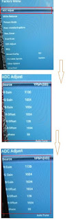
Factory mode
To perform extended alignments.
To perform extended alignments.
How to Activate the Factory mode
To activate the Factory mode, use the following method:
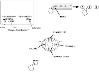
Press the following key sequence on the remote control transmitter: from the “menu/home” press “1999”, directly followed by the“Back/Return” button. Do not allow the display to time out between entries while keying the sequence.
After entering the Factory mode, we can see many items displayed, use the UP/DOWN keys to display the next/previous menu items
To activate the Factory mode, use the following method:
Press the following key sequence on the remote control transmitter: from the “menu/home” press “1999”, directly followed by the“Back/Return” button. Do not allow the display to time out between entries while keying the sequence.
After entering the Factory mode, we can see many items displayed, use the UP/DOWN keys to display the next/previous menu items
How to Exit the Factory mode
Use one of the following methods:
Select EXIT_FACTORY from the menu and press the “OK” button.
Note: When the TV is switched “off” by a power interrupt, or normal switch to “stand-by” while in the factory mode, the TV will show up in “normal operation mode” as soon as the power is supplied again. The error buffer will not be cleared.
Customer Service Mode (CSM)
The Customer Service Mode shows error codes and information on the TVs operation settings.The call centre can instruct the customer (by telephone) to enter CSM in order to identify the status of the set.This helps the call centre to diagnose problems and failures in the TV set before making a service call.
The CSM is a read-only mode; therefore, modifications are not possible in this mode.
Ignore “Service unfriendly modes”.
Line number for every line (to make CSM language independent).
Set the screen mode to full screen (all contents on screen is visible).
After leaving the Customer Service Mode, the original settings are restored.
Possibility to use “CH+” or “CH-” for channel surfing, or enter the specific channel number on the RC.
How to Activate CSM
To activate CSM, press the following key sequence on a standard remote control transmitter: “456987” (do not allow the display to time out between entries while keying the sequence). After entering the Customer Service Mode, the following items are displayed. use the Right/Left keys to display the next/previous menu items
Note: Activation of the CSM is only possible if there is no (user) menu on the screen.
How to Navigate
By means of the “CURSOR-DOWN/UP” knob (or the scroll wheel) on the RC-transmitter, can be navigated through the menus.
By means of the “CURSOR-DOWN/UP” knob (or the scroll wheel) on the RC-transmitter, can be navigated through the menus.
How to Exit CSM
To exit CSM, use one of the following methods.
Press the MENU/HOME button on the remote control transmitter.
Press the POWER button on the remote control transmitter.
Press the POWER button on the television set.
To exit CSM, use one of the following methods.
Press the MENU/HOME button on the remote control transmitter.
Press the POWER button on the remote control transmitter.
Press the POWER button on the television set.
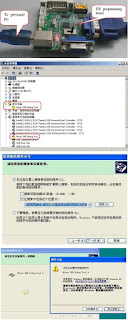
Software Upgrading
The following update is for .bin file.
1. Rename the file to “Usb_update.bin”
2. Prepare a USB memory.
3. Copy the software to USB flash disk(root directory).
4. Switch off the TV and Insert the USB memory stick that contains the software update files in one of the TV’s USB 2.0 ports.
5. Switch on the TV. The TV will detect the USB memory s tick automatically.
6. When the TV software is updated, the TV will turn on again automatically. Remove your USB flash drive.
7. We can enter in CSM or Factory mode to check the current software version.
7. We can enter in CSM or Factory mode to check the current software version.
Check the SW version
1. After burning software, TV will restart
2. Press “Menu+1999+back”, enter Factory mode to check if the software version is correct
Caution: Please make sure that software upgrade is finished before unplug the USB and AC power.
1. After burning software, TV will restart
2. Press “Menu+1999+back”, enter Factory mode to check if the software version is correct
Caution: Please make sure that software upgrade is finished before unplug the USB and AC power.


Power Supply Unit
All power supplies are a black box for Service. When defective, a new board must be ordered and the defective one must be returned, unless the main fuse
of the board is broken. Always replace a defective fuse with one with the correct specifications! This part is available in the regular market.
Consult the Philips Service web portal for the order codes of the boards.
Important delta’s with the platform are:
New power architecture for LED backlight
“Boost”-signal is now a PWM-signal + continuous variable
The control signals are
PS-ON
Lamp “on/off”
DIM (PWM) (not for PSDL)
No detailed information is available because of design protection issues.
+12 output (on-mode)
+12V_audio (audio AMP power)
Output to the display; in case of
- IPB: High voltage to the LCD panel
- PSL and PSLS (LED-driver outputs)
- PSDL (high frequent) AC-current.
DiversityAll power supplies are a black box for Service. When defective, a new board must be ordered and the defective one must be returned, unless the main fuse
of the board is broken. Always replace a defective fuse with one with the correct specifications! This part is available in the regular market.
Consult the Philips Service web portal for the order codes of the boards.
Important delta’s with the platform are:
New power architecture for LED backlight
“Boost”-signal is now a PWM-signal + continuous variable
The control signals are
PS-ON
Lamp “on/off”
DIM (PWM) (not for PSDL)
No detailed information is available because of design protection issues.
+12 output (on-mode)
+12V_audio (audio AMP power)
Output to the display; in case of
- IPB: High voltage to the LCD panel
- PSL and PSLS (LED-driver outputs)
- PSDL (high frequent) AC-current.
The diversity in power supply units is mainly determined by the diversity in displays.
The following displays can be distinguished:
CCFL/EEFL backlight: power panel is conventional IPB
LED backlight:
- side-view LED without scanning: PSL power panel
The following displays can be distinguished:
CCFL/EEFL backlight: power panel is conventional IPB
LED backlight:
- side-view LED without scanning: PSL power panel
- side-view LED with scanning: PSLS power panel
- direct-view LED without 2D-dimming: PSL power panel
- direct-view LED with 2D-dimming: PSDL power panel.
PSL stands for Power Supply with integrated LED-drivers.
PSLS stands for a Power Supply with integrated LED-drivers with added Scanning functionality (added microcontroller).
PSDL stands for a Power Supply for Direct-view LED backlight with 2D-dimming.
DC/DC Converters
The on-board DC/DC converters deliver the following voltages(depending on set execution):
PVDD from the power 12V_AMP for the AUDIO AMP.
3V3SB, permanent voltage for the Stand-by controller, LED/IR, keyborad receiver and controls.
+12V, input from the power supply for the panel common(active mode)
+12V, input from the power supply for the AMP
DDRV supply voltage for DDR
TUNER3.3V, supply voltage for tuner
+5V_SW, input intermediate supply voltage for the USB Power
3V3SB, from the power supply for the scaler IC MT5561
DVDD3V3, +1V2,clean voltage for Demodulator IC channel decoder.