Quantcast
Channel: Electro help
Viewing all 2033 articles
Browse latest View live

Technics SL-L2 direct drive automatic turntable-How to troubleshoot, How to disassemble

$
0
0

Technics Quartz Direct Drive automatic turntable system SL-L2[M] – troubleshooting, disassembly, mechanical and electrical adjustments
How to remove turntable platter
Open the upper cabinet.
Remove the turntable mat, and lift the turntable platter.
[when removing turntable platter, it is not necessary to remove the 45rpm adopter.  The turntable platter is tightly fitted to the center spindle.  When removing it, take care not to damage the upper cabinet.}
To remove the dust cover,
Remove the terminal solder by using a solder sucker.
Hold the Hall element with tweezers and remove it while touching the soldering iron to the terminal.
(Fit the hall element with the part number Print “UP”.
How to remove the tonearm.
Remove the dust cover.
Remove the shield cover setscrew.
Unsolder the 5 lead wires.
Turn the worm gear with your fingers to remove the tonearm inward.
To remove the offset angle detection circuit board.
Remove the indicator cover setscrew.
Remove the indicator cover.
How to remove the arm dirive motor.
Remove the dust cover.
Remove the two setscrews.
Unsolder the two lead wires from the motor.
Open the cushion rubber.
How th remove the stylus set-down position volume circuit board setscrew.
Remove the cover.
Remove the stylus set-down position volume circuit board setscrew.
How to remove the reset switch.
Remove the screw.
Remove the two claws of the switch holder.
Unsolder the two switch terminals.
[when replacing the reset switch, be sure to open the upper cabinet]
How to set the tonearm drive chord.
Remove the dust cover and tonearm cover.
Remove the roller cover.
Set the chord in the order of steps 1 to 6.
Fit the chord connector to the tonearm.
Set the roller cover and turn the worm gear by hand to see the torn am moves.
How to remove the 45 rpm adapter.
The two adapter claws fit into the turntable platter.  Remove the 45rpm adapter by pushing by pausing it in. [when removing the 45rpm adapter, remove the turntable platter; otherwise the adapter claws will be broken.]
How to remove turntable platter.
Open the upper cabinet. Remove the turntable mat, and lift the turntable platter. [when removing the platter, it is not necessary to remove the 45rpm adapter.  The turntable platter is tightly fitted to the center spindle.  When removing the platter, take care not to damage the upper cabinet.
How to remove the bottom board.
Turn over the unit on a soft cloth.
Remove the six screws.
How to remove the power switch.
Remove the three screws.
Lift the holder slightly.
Pull out the power switch.
How to remove the Hall element.
Remove the terminal solder.
Hold the Hall element with a tweeter and remove it while touching the soldering iron to the terminal.
How to use the repair table.
Remove the bottom board.
Remove the operation circuit board and connect the PCB ground terminal to the chassis (stator frame)
Put the unit on the repair table.
Fit the turntable platter and put the turntable mat.
Put on the record and check the circuit from under the unit.
How to raise the set.
Turntable platter is not fixed on the center spindle.  Take care so that the platter will not come loose. Take care allow the set the set to fall down.
Remove the bottom board.
Completely open the upper cabinet.
Hold the reset switch (cabinet) with the tape.
Fit the turntable platter.
Raise the unit and check the circuit.
How to turn over the set.
The purpose is to check the voltage of each circuit point during stop of the turntable.
Remove the turntable platter and turn over the unit.
Remove the bottom board.
Turn the power switch ON and check the voltage.
How to remove the cartridge.
Open the upper cabinet.
Remove the setscrew and pull out the cartridge. [when attaching the cartridge, match the tonearm connector with the cartridge pin, and completely insert it and tighten the setscrew.]
Adjustment points.
Turntable drive control schematic
Troubleshooting Measurements and adjustments
Start position:
Open the upper cabinet and put on the record.
Turn the power switch ON.
Push the Start switch.
Turn the start position adjusting screw.  If it descends between tunes, turn it counterclockwise.
Clock frequency:
Connect the lead wire with clip to IC301 29pin of operation circuit board.
Connect the scope to IC301 8pin.
turn the power switch ON.
Adjust VR301 so that the cycle of the output waveform is 1.6msec +/-0.06msec.
Sensor gain:
Connect DC voltmeter to IC401 12pin + and Ground.
Put on the record for adjustment with A side up.
Turn the power switch ON.
Torn arm is on a between songs gap [blank area of the reord]
Adjust VR401 so that the output voltage is 8.5 +/- 0,3v.
Sensor resolution:
Connect the Scope to the IC401 9pin + to ground.
Put on the record for adjustment with slide A up.
Turn the power switch ON.
Keep the ‘F’skip switch depressed to move the tonearm. (output is delivered between tunes is 3.0 +/- 0.3v.
Stylus cue-down position: open the upper cabinet and hold the cabinet switch with tape.
Put on the record for adjustment with side B up.
Close the upper cabinet.
Connect the unit to amplifier (connect the speakers to the speaker terminals)
Turn the power switch ON.
Press the ‘F’ skip switch twice and then press the start switch.
After completion of cueing, again press the ‘B’ skip switch to cue down.
Make sure that the descending position is around 18 – 19.
Tonearm offset angle:
Remove the dust cover. Open the upper cabinet and hold the cabinet switch with tape.
Close the upper cabinet.
Put on the record.
Turn the power switch ON.
Keep the ‘F’ skip switch depressed to move the tonearm.
Turn the adjusting screw so that the arm center matches the V-groove of the lift bar.
Servo gain and offset voltage:
Remove the dust cover.
Open the upper cabinet and hold the cabinet switch with tape.
Connect the DC voltmeter to CN301 5-pin + and Ground.
Remove the sensor cover.
Turn the power switch ON.
Keep the ‘F’ skip switch depressed to move the tonearm.
Open the upper cabinet.
Completely shift the tonearm to the left, and then adjust VR501 so that the voltage is 6.0V[servo gain].
Set the tonearm to the center and make sure that the output voltage is 3.0v.
If the voltage is not 3.0v, adjust the set screw, so that the output voltage is 3.0v [offset voltage].


40pfl9401 Philips, Sanyo FW40D36F- 40 inch LCD TV Chassis PL15-01 service mode, softare update service adjustments

$
0
0
TYPE A
40PFL4901/F7 PHILIPS (Serial No.: ME4)
40PFL4901/F8 PHILIPS (Serial No.: XA1)
40PFL4911/F8 PHILIPS (Serial No.: XA1)
TYPE B
FW40D36F SANYO (Serial No.: ME3)
The LCD panel is manufactured to provide many years of useful life.
Occasionally a few non active pixels may appear as a tiny spec of color.
This is not to be considered a defect in the LCD screen.
How to Remove / Install Flat Pack-IC
With Hot-Air Flat Pack-IC De=soldering Machine
1. Prepare the hot-air flat pack-IC de-soldering machine, then apply hot air to the Flat Pack-IC (about 5 to 6 seconds).
2. Remove the flat pack-IC with tweezers while applying the hot air.
3. Bottom of the flat pack-IC is fixed with glue to the CBA; when removing entire flat pack-IC, first apply soldering iron to center of the flat pack-IC and heat up. Then remove (glue will be melted).
4. Release the flat pack-IC from the CBA using tweezers.
The Flat Pack-IC shape may differ by models. Use an appropriate hot-air flat pack-IC de-soldering machine, whose shape matches that of the Flat Pack-IC.
2. Do not supply hot air to the chip parts around the flat pack-IC for over 6 seconds because damage to the chip parts may occur. Put masking tape around the flat pack-IC to protect other parts from damage.
3. The flat pack-IC on the CBA is affixed with glue, so be careful not to break or damage the foil of each pin or the solder lands under the IC when removing it.
With Soldering Iron
1. Using de=soldering braid, remove the solder from all pins of the flat pack-IC. When you use solder flux which is applied to all pins of the flat pack-IC, you can remove it easily.
2. Lift each lead of the flat pack-IC upward one by one, using a sharp pin or wire to which solder will not adhere (iron wire). When heating the pins, use a fine tip soldering iron or a hot air de=soldering machine.
3. Bottom of the flat pack-IC is fixed with glue to the CBA; when removing entire flat pack-IC, first apply soldering iron to center of the flat pack-IC and heat up. Then remove (glue will be melted).
4. Release the flat pack-IC from the CBA using tweezers.
With Iron Wire
1. Using de=soldering braid, remove the solder from all pins of the flat pack-IC. When you use solder flux which is applied to all pins of the flat pack-IC, you can remove it easily.
2. Affix the wire to a workbench or solid mounting point.
3. While heating the pins using a fine tip soldering iron or hot air blower, pull up the wire as the solder melts so as to lift the IC leads from the CBA contact pads.
4. Bottom of the flat pack-IC is fixed with glue to the CBA; when removing entire flat pack-IC, first apply soldering iron to center of the flat pack-IC and heat up. Then remove (glue will be melted).
5. Release the flat pack-IC from the CBA using tweezers.
Note: When using a soldering iron, care must be taken to ensure that the flat pack-IC is not being held by glue. When the flat pack-IC is removed from the CBA, handle it gently because it may be damaged if force is applied.
Installation
1. Using de-soldering braid, remove the solder from the foil of each pin of the flat pack-IC on the CBA so you can install a replacement flat pack-IC more easily.
2. The “I” mark on the flat pack-IC indicates pin 1.  Be sure this mark matches the
pin 1 on the PCB when positioning for installation.  Then pre-solder the four corners of the flat pack-IC.
3. Solder all pins of the flat pack-IC. Be sure that none of the pins have solder bridges.
Disassembly Flowchart
The disassembly steps for the cabinet parts and the CBA in order to gain access to items to be serviced. When reassembling, follow the steps in reverse order. Bend, route and dress the cables as they were.
(1) Order of steps in procedure. When reassembling, follow the steps in reverse order. These numbers are also used as the Identification (location)
(2) Parts to be removed or installed.
(3) Fig. No. showing procedure of part location
(4) Identification of parts to be removed, unhooked, unlocked, released, unplugged, unclamped, or desoldered.
P = Spring, L = Locking Tab, S = Screw,
H = Hex Screw, CN = Connector
e.g. 2(S-2) = two Screws of (S-2),
2(L-2) = two Locking Tabs of (L-2)
When you disassemble/re-assemble the Rear Cabinet Assembly.
• Do not pull the FFC Cable and Board Cable forcefully when you re-assemble.
• Be careful not to scratch the display panel when assembling.
When you disassemble/re-assemble the Function CBA Unit or the IR Sensor CBA Unit.
• Be careful not to break the hooks. If you pull with too much force, the hooks may be damaged.
• Make sure the hooks are securely in place when assembling.
• The Function CBA Unit, Function Knob and Knob
Frame are fixed in place by the hooks. Make sure these hooks are not damaged. Make sure the Function CBA Unit, Function Knob and Knob Frame are securely in place when re-assembling.
• The IR Sensor CBA Unit and Sensor Shield are fixed in place by the hooks. Make sure these hooks are not damaged. Make sure the IR Sensor CBA Unit and Sensor Shield are securely in place when re-assembling.
When you disassemble/re-assemble the Front Cabinet.
• Make sure to replace the Decoration Plate, LED Lens and Leading Edge Cover*5  to a new one when replacing the Front Cabinet.
Electrical adjustments are required after replacing circuit components and certain mechanical parts. It is important to perform these adjustments only after all repairs and replacements have been completed.
Also, do not attempt these adjustments unless the proper equipment is available.
How to set up the service mode
Turn the power on.
2. Press [0], [6], [2], [5], [9], [6] and [INFO] buttons on the remote control unit in this order. The relevant screen appears.
Purity Check Mode
This mode cycles through full-screen displays of red, green, blue, and white to check for non-active pixels.
1. Enter the service mode.
2. Each time the [7] button on the remote control unit is pressed, the display changes as follows.
3. To cancel or to exit from the Purity Check Mode, press [CH RETURN] or [PREV CH] button.
White Balance Adjustment
Symptom of Misadjustment: White becomes bluish or reddish.
1. Operate the unit for more than 30 minutes.
2. Enter the service mode.
3. Press [VOLUME DOWN] button three times on the remote control unit to select “Drive setting” mode.  “Drive -” appears in the screen.
4. Set the color analyzer at the CHROMA mode and zero point calibration. Bring the optical receptor pointing at the center of the LCD-Panel.
[To avoid interference from ambient light, this adjustment should be performed in a dark room]
[The optical receptor must be set perpendicularly to the LCD Panel surface]
5. Press [3] button to select the “HDB” for High Drive Blue adjustment. (“HDB” appears in the screen.)
6. Press [MENU] button. The internal Raster signal appears in the screen. (“Internal (Single)” appears in the upper right of the screen.
7. Press [CHANNEL UP/DOWN] buttons to adjust the color temperature becomes 12000°K (x= 0.272 / y= 0.278 ± 0.003).
8. Press [1] button to select the “HDR” for High Drive Red adjustment (“HDR” appears in the screen.) and press [CHANNEL UP/DOWN] buttons to adjust the color temperature.
9. If necessary, adjust the “HDB”, “HDR” again.
10. Press [9] button to select the “LDB” for Low Drive Blue adjustment (“LDB” appears in the screen.) and press [CHANNEL UP/DOWN] buttons to adjust the color temperature.
11. Press [7] button to select the “LDR” for Low Drive Red adjustment (“LDR” appears in the screen.) and press [CHANNEL UP/DOWN] buttons to adjust the color temperature.
12. Press [8] button to select the “LDG” for Low Drive Green adjustment (“LDG” appears in the screen.) and press [CHANNEL UP/DOWN] buttons to adjust the color temperature.
13. If necessary, adjust the “LDB”, “LDR” or “LDG” again.
14. Press [VOLUME DOWN] button to shift to the “Debugging Message” mode.
If there is no message under “[WB]” section, this adjustment completes.
If “Drive settings are NG. Retry again.” Is displayed, repeat above steps from 5. to 13. Then check “Debugging Message” again. If “Drive settings are NG. Retry again.” is displayed, replace the LCD Panel or Digital Main CBA.
15. To cancel or to exit from the White Balance Adjustment, press [CH RETURN] or [PREV CH] button.
 [TYPE B] Sanyo
Service mode
1. Turn the power on.
2. Press [MENU] button to display Setup menu.
3. Select “Features”.
4. Select “Software Upgrade”.
5. Select “Current Software Info”.
6. Press [0], [4], [2], [5], [7], [4] and [INFO] buttons on the remote control unit in this order.
Service mode dispay is somewhat different to that of Type-A.  Other adjustment parameters are the same to that of Type-1.  But some adjustments to white balance are differs.  Please note them.
White Balance Adjustment
1. Operate the unit for more than 60 minutes.
2. Enter the service mode.
3. Press [VOLUME DOWN] button three times on the remote control unit to select “Drive setting” mode. “Drive” appears in the screen.
4. Set the color analyzer at the CHROMA mode and zero point calibration. Bring the optical receptor pointing at the center of the LCD-Panel.
To avoid interference from ambient light, this adjustment should be performed in a dark room.
[The optical receptor must be set perpendicularly to the LCD Panel surface.]
5. Press [3] button to select the “HDB” for High Drive Blue adjustment. (“HDB” appears in the screen.)
6. Press [MENU] button. The internal Raster signal appears in the screen. (“Internal (Single)” appears in the upper right of the screen.
7. Press [CHANNEL UP/DOWN] buttons to adjust the color temperature becomes 12000°K (x= 0.272 / y= 0.278 ± 0.003).
8. Press [1] button to select the “HDR” for High Drive Red adjustment (“HDR” appears in the screen.) and press [CHANNEL UP/DOWN] buttons to adjust the color temperature.
9. Press [2] button to select the “HDG” for High Drive Green adjustment (“HDG” appears in the screen.) and press [CHANNEL UP/DOWN] buttons to adjust the color temperature.
10. If necessary, adjust the “HDB”, “HDR” or “HDG” again,
11. Press [6] button to select the “LDB” for Low Drive Blue adjustment (“LDB” appears in the screen.) and press [CHANNEL UP/DOWN] buttons to adjust the color temperature.
12. Press [4] button to select the “LDR” for Low Drive Red adjustment (“LDR” appears in the screen.) and press [CHANNEL UP/DOWN] buttons to adjust the color temperature.
13. Press [5] button to select the “LDG” for Low Drive Green adjustment (“LDG” appears in the screen.) and press [CHANNEL UP/DOWN] buttons to adjust the color temperature.
14. If necessary, adjust the “LDB”, “LDR” or “LDG” again.
15. Press [VOLUME DOWN] button to shift to the “Debugging Message” mode.
If there is no message under “[WB]” section, this adjustment completes.
If “Drive settings are NG. Retry again.” Is displayed, repeat above steps from 5. to 14. Then check “Debugging Message” again. If “Drive settings are NG. Retry again.” is displayed, replace the LCD Panel or Digital Main CBA.
16. To cancel or to exit from the White Balance Adjustment, press [CH RETURN] or [PREV CH] button.
How to initialize the lcd tv
The purpose of initialization is to place the set in a new out of box condition. The customer will be prompted to select a language and program channels after the set has been initialized.
To put the program back at the factory-default, initialize the LCD TV using the following procedure.
[Disconnect any device from the USB Port before you conduct on this procedure.]
[TYPE A]
1. Turn the power on.
2. Enter the service mode.
- To cancel the service mode, press [ ] button on the remote control unit.
3. Press [BACK] button to enter the Control Panel Key Confirmation Menu.
4. Press all buttons on the control panel.
5. Press [INFO] button to proceed with the self check mode.
6. Make sure to confirm the "INITIALIZED : OK" appears in the green screen.
7. Unplug the AC Cord and plug it back on again.
 [TYPE B]
1. Turn the power on.
2. Enter the service mode.
- To cancel the service mode, press [ ] button on the remote control unit.
3. Press [BACK] button to enter the Control Panel Key Confirmation Menu.
4. Press all buttons on the control panel.
5. Press [INFO] button to proceed with the self check mode.
6. Make sure to confirm the “INITIALIZED FINISH” appears in the green screen.
7. Unplug the AC Cord and plug it back on again.
Firmware renewal mode
[TYPE A]
User Upgrade (Filename example: PHL-0C0HB_***_*.upg)
Upgrade the firmware only. The setting values will not be initialized. Update procedure
1. Plug the AC Cord and turn the power on.
2. Insert the USB storage device to the USB port.
3. Press the [MENU] button on the remote control unit.
4. Select “Setup” and press the [OK] button to display the setup menu.
5. Select “Update software” and press the [OK] button on the remote control unit.
6. Select “USB” and press the [OK] button on the remote control unit to enter the update mode.
Update file selection screen appears as follows. (Files included in the USB storage device are displayed.)
[To cancel the update mode, select “Cancel” and press the [OK] button.]
7. Select the file and press [OK] button.
8. The update will start and the following will appear.
[If that screen isn’t displayed, repeat from step 1.]
9. Select “Yes” and press the [OK] button to update.
Note: Do not remove the USB storage device or turn the TV off while update is in progress.
10. When the firmware update is completed, the relevant screen will appear in the screen.
Remove the USB storage device from the USB port.
Turn the power off and turn the power on again.
11. Updating software is started, the following will appear in the screen.
12. After finished the updating software, TV set will automatically reboot.
[TYPE B]
Firmware Update Procedure
User Upgrade (Filename example: TVNB3xxx_00_3H_XX91_HC10.bin)
Upgrade the firmware only. The setting values will not be initialized.
The User Upgrade and the Firmware Upgrade (Factory Upgrade) will be done by the same file. If you want to upgrade the firmware and initialize the setting values also, add “FACT_” at the beginning of the filename.
If you want to upgrade the firmware only and leave the setting values as they are, eliminate the “FACT_” from the filename.
Update procedure
1. Turn the power on.
2. Press [MENU] button to display Menu.
3. Select “Features”.
4. Select “Software Upgrade”.
5. Select “Upgrade” to display Upgrade screen.
6. Press [OK] button to display Software Upgrade screen.
7. Select “USB” and press [OK] button.
8. Insert the USB storage device to the USB port.
9. Select “Check” and press [OK] button.
10. Select “Upgrade” and press [OK] button to start software upgrade.
11. The update will start and the following will appear in the screen.
12. When the firmware update is completed, the relevant will appear.
[If the screen isn’t displayed, repeat from step 1]
Remove the USB storage device from the USB port. Turn the power off and turn the power on again.
Factory Upgrade (Firmware Upgrade/Flash Upgrade)
Firmware Upgrade
(Filename example: FACT_TVNB3xxx_00_3H_XX91_HC10.bin)
Upgrade the firmware and initialize the setting values.
The User Upgrade and the Firmware Upgrade (Factory Upgrade) will be done by the same file. If you want to upgrade the firmware and initialize the setting values also, add “FACT_” at the beginning of the filename.
If you want to upgrade the firmware only and leave the setting values as they are, eliminate the “FACT_” from the filename.
Flash Upgrade
(Filename example: ALL_TVNB3xxx_00_3H_XX91_HC10.bin)
Upgrade the firmware and initialize the setting values along with the factory default such as White Balance, etc.
Before the upgrade, you will need to make a note of all the factory default so you will be able to set it back on the TV after the initialization.
The Flash Upgrade will be done by it's unique file.
The User Upgrade/Firmware Upgrade (Factory Upgrade) file cannot be used for this upgrade.
Update procedure
1. Turn the power off.
2. Insert the USB storage device to the USB port.
3. Turn the power on.
4. The update will start and the following will appear
in the screen.
[Software upgrade in progress. Please wait.  Do not remove the USB storage device or turn the TV off while upgrade is in progress.]
[If that screen isn’t displayed, repeat from step 1]
5. When the firmware update is completed, the following will appear in the screen.  Remove the USB storage device from the USB port.  Turn the power off and turn the power on again.
Service mode initial screen with a word “INITIALIZED” will appear in the screen. The color of the word “INITIALIZED” will change from red to green when initialization is completed.

JBL SUB350 Dolby Pro-Logic Surround Amplifier/Subwoofer – How to disassemble the sub-woofer, schematic diagram, general troubleshooting

$
0
0

Please do not try to attempt any repair work; if you’re not well experienced in service field.
The troubleshooting described here is the only thing you can do as a user.
Total System Output - 200 watts
Front channels – 35 watts x 3 @ .1% THD
Surround channels – 15 watts x 2 @.1% THD
Subwoofer – 65 watts @ .1% THD
Frequency response - 35Hz – 20kHz
Dimensions - 15 1/8 x 13 x 14 ½” (384 x 330 x 368mm)
Input Impedance - 20k Ohms
Audios output IC – STK4151

Weight - 34.5 lbs. (15.7 kg)
Troubleshooting
If there is no sound from any of the speakers, check the following:
• Make sure the subwoofer is plugged into an active AC wall outlet.
• Make sure the Master Power Switch, located on the rear of the subwoofer, is in the “On/Standby” position.
• Make sure there is a source – for example, a VCR or television – hooked up to the TV or tape/aux input jacks on The Source.
• Make sure that the program material is playing.
• Recheck the hookup connections.  If most of the sound comes from the center-channel speaker, with little or no information from the surround channels, note the following:
Although most of today’s televisions are equipped with stereo audio output jacks, some stereo televisions have poor audio sections and are unable to provide a Dolby Pro Logic encoded signal. In the unlikely event that you experience this problem, connecting the audio outputs from your hi-fi VCR, laser disc player, DVD player, or satellite receiver directly to one of the inputs on The Source will provide a proper audio signal and allow you to enjoy true Dolby Pro Logic surround sound.
If there is no sound from the surround speakers or sound is very low, check the following:
• Check all connections between the amplifier and each of the speakers.
• Raise the surround volume  from the remote control.
• Make sure the TV show or movie you are watching is recorded in Dolby Surround.
If there is no sound from the center speaker, check the following:
• Make sure that the processor is in the Pro Logic mode. If it is in Phantom or Stereo mode, the center speaker will not play.
• Check the connections between the subwoofer and the center speaker.
If you have low bass output, check the following:
• Experiment with placement of the subwoofer. Remember, place the subwoofer in a corner to get maximum bass output from the system.
• Increase the level of bass, using the remote control.
• Adjust the level control on the rear of the subwoofer.
If you are having trouble picking up radio stations, check the following:
• Make sure the antenna is hooked up properly.
• Depending on your distance from the station’s transmitter, you may need to install an FM antenna on the roof or in the attic.
Sub exploded view
Fig-1
JBL SUB350 Dolby Pro-Logic Surround Amplifier/Subwoofer – How to disassemble the sub-woofer, schematic diagram, general troubleshooting
Please do not try to attempt any repair work; if you’re not well experienced in service field.
The troublleshooting described here is the only thing you can do as a user.
Exploded view
Schematic


Panasonic CTL1400-LH13 CHASSIS LCSD TV how to enter the service mode, service adjustments in details

$
0
0

Self-check function
When phenomena like "the power fails from time to time" or "the video/audio fails from time to time" can not be confirmed at the time of servicing, the self-check function can be used to confirm the occurrence and to limit the scope for the defective circuits. When "the power fails from time to time", display on the screen can be used to confirm the occurrence and to limit the scope for the defective circuits.
Any programmed channels, channels caption data and some other user defined settings will be erased and return to factory setting.
Access
Produce TV reception screen and, while pressing [VOLUME-] button on the main unit, press [SLEEP] button on the remote controller unit simultaneously.
Exit
When one of the buttons for channel selection etc. is pressed, the display returns to the normal screen.
How to remove the connectors
Disassembly
Rear cover
1. Thick cloth and so on is down not to damage a LCD screen, and the unit is pushed down.
2. Remove the screw (1 pcs), and detach the hinge cover and the AV cable cover
3. Remove the screws (7 pcs), the screws (2 pcs), and the screws (4 pcs), and detach the rear cover and top cover.
AP-BOARD
1. Remove the rear cover.
2. Remove the screws (5 pcs) and the screws (2 pcs) and detach the shield plate.
3. Disengage the shaft holder hook and detach the power button shaft.
4. Remove the screw (1 pcs) and disconnect the couplers (B2 (AP2) and B3 (AP3)) between B-Board and the AP-Board
5. Disconnect the couplers (AP4, AP5, AP6, AP7 and AP8) the flexible cable (AP1 and AP9) and remove the screws (3 pcs) and detach the AP-Board.
[Caution: PCB Fixing screws driving torque: 0.2-0.3 N·m (2-3kg·mm) Do not tighten screws so hard.]
DG-Board
1. Remove the rear cover.
2. Remove the screws (5 pcs) and the screws (2 pcs) and detach the shield plate.
3. Disconnect the flexible cable (DG4 and DG5) and remove the screws (2 pcs) and detach the DG-Board.
[Caution: PCB Fixing screws driving torque: 0.2-0.3 N·m (2-3kg·mm). Do not tighten screws so hard.]
V-Board
1. Remove the rear cover.
2. Remove the screw (1 pcs) and disconnect the couplers (V2 and V3) and the flexible cable (V9) and detach the V-Board.
Speaker (L, R)
1. Remove the rear cover.
2. Remove the screw (1 pcs) and the screws (6 pcs) and disconnect the couplers (V2 and V3) and the Speakers (L,R).
B-Board
1. Remove the rear cover.
2. Remove the screw (5 pcs) and the screws (2 pcs) and detach the shield plate.
3. Remove the screw (1 pcs) and disconnect the couplers (B2 (AP2) and B3 (AP3)) between B-Board and the AP-Board.
Caution: PCB Fixing screws driving torque: 0.2-0.3 N·m (2-3kg·mm) Do not tighten screws so hard.
K-Board
1. Remove the rear cover.
2. Remove the screws (5 pcs) and the screws (2 pcs) and detach the shield plate.
3. Disconnect the coupler (AP8) and disengage the hook (2 pcs) and detach the K-Board.
[Caution: PCB Fixing screws driving torque: 0.2-0.3 N·m (2-3kg·mm)
Do not tighten screws so hard.]
LCD panel
1. Remove the rear cover.
2. Remove the screws (5 pcs) and the screws (2 pcs) and detach the shield plate.
3. Disengage the shaft holder hook and detach the power button shaft.
4. Disconnect the coupler (AP8) and detach the circuit board K bracket with K-Board.
5. Remove the screw (1 pcs) and disconnect the couplers (B2 (AP2) and B3 (AP3)) between B-Board and the AP-Board.
6. Disconnect the couplers (AP4, AP6, BL4 and BL6) and the flexible cable (AP9, DG4 and DG5) and remove the screws (7 pcs) and detach the AP-Board, DG-Board and BL-Board
7. Remove the screws (2 pcs), detach the LCD panel.
How to enter into adjustment mode
While pressing [VOLUME-] button of the main unit, press [RECALL] button of the remote control transmitter three times in a row (within 2 seconds).
Adjustment method.....Use the remote control.
“1” button...Main items Selection in forward direction
“2” button...Main items Selection in reverse direction
“3” button...Sub items Selection in forward direction
“4” button...Sub items Selection in reverse direction
Cancellation
Switch off the power with the [POWER] button on the main unit or the [POWER] button on the remote control.
Contents of adjustment mode
 Value is shown as a hexadecimal number.
 Preset value differs depending on models.
 After entering the adjustment mode, take note of the value in each item before starting adjustment.
[[GAMMA adjustment is for factory adjustment only. Do not change the value.]]
NTSC picture RF
Receive 75% color bar signal
 Enter the adjustment mode and adjust the amplitude level of each signal in the following steps.
1. Y signal
With [VOLUME+/-] buttons of the remote control transmitter, adjust the value appearing below YGAIN indication so that the value below MAX indication becomes B8.
2. B-Y signal (TP238)
With [VOLUME+/-] buttons of the remote control transmitter, adjust the value appearing below B-Y indication so that the amplitude (white-blue) at TP238 becomes 0±0.03V.
3. R-Y signal (TP236)
With [VOLUME+/-] buttons of the remote control transmitter, adjust the value appearing below R-Y indication so that the amplitude (white-red) at TP236 becomes 0±0.03V.
NTSC picture video (VBS)
Receive 100% color bar signal at video input 1.
 Enter the adjustment mode and adjust the amplitude level of each signal in the following steps.
1. Y signal
With [VOLUME+/-] buttons of the remote control transmitter, adjust the value appearing below YGAIN indication so that the value below MAX indication becomes B8.
2. B-Y signal (TP238)
With [VOLUME+/-] buttons of the remote control transmitter, adjust the value appearing below B-Y indication so that the amplitude (yellow-blue) at TP238 becomes 0±0.03V.
3. R-Y signal (TP236)
With [VOLUME+/-] buttons of the remote control transmitter, adjust the value appearing below R-Y indication so that the amplitude (cyan-red) at TP236 becomes 0±0.03V.
NTSC picture video (S terminal)
Receive 100% color bar signal at video input 1 (S terminal).
 Enter the adjustment mode and adjust the amplitude level of each signal in the following steps.
1. Y signal
With [VOLUME+/-] buttons of the remote control transmitter, adjust the value appearing below YGAIN indication so that the value below MAX indication becomes B8.
2. B-Y signal (TP238)
With [VOLUME+/-] buttons of the remote control transmitter, adjust the value appearing below B-Y indication so that the amplitude (yellow-blue) at TP238 becomes 0±0.03V.
3. R-Y signal (TP236)
With [VOLUME+/-] buttons of the remote control transmitter, adjust the value appearing below R-Y indication so that the amplitude (white-red) at TP236 becomes 0±0.03V.
NTSC Component (525i) level adjustment
Receive 100% color bar signal at video input 1 (S terminal).
 Enter the adjustment mode and adjust the amplitude level of each signal in the following steps.
1. Y signal
With [VOLUME+/-] buttons of the remote control transmitter, adjust the value appearing below YGAIN indication so that the value below MAX indication becomes DC.
2. B-Y signal (TP238)
With [VOLUME+/-] buttons of the remote control transmitter, adjust the value appearing below B-Y indication so that the amplitude (yellow-blue) at TP238 becomes 0±0.03V.
3. R-Y signal (TP236)
With [VOLUME+/-] buttons of the remote control transmitter, adjust the value appearing below R-Y indication so that the amplitude (cyan-red) at TP236 becomes 0±0.03V.
NTSC Component (525p) level adjustment
Receive 100% color bar signal at video input1 (S terminal).
 Enter the adjustment mode and adjust the amplitude level of each signal in the following steps.
1. Y signal
With [VOLUME+/-] buttons of the remote control transmitter, adjust the value appearing below YGAIN indication so that the value below MAX indication becomes B8.
2.B-Y signal (TP238)
With [VOLUME+/-] buttons of the remote control transmitter, adjust the value appearing below B-Y indication so that the amplitude (white-blue) at TP238 becomes 0±0.03V
3. R-Y signal (TP236)
With [VOLUME+/-] buttons of the remote control transmitter, adjust the value appearing below R-Y indication so that the amplitude (white-red) at TP236 becomes 0±0.03V.
Flicker Adjustment
1. Enter the adjustment mode and select the " FLICKR".
2. Adjust the Flicker Adjustment until the flicker displayed on the screen is minimum.
Note: Adjustment shall be done after it is made to overrun value of adjustment once as shown figure A.
Note: Make the adjustment to look for the optimum point because the level of flicker doesn´t disappear on the screen completely.
MTS Adjustment
Caution:
MTS adjustment shall be after the aging of 30 minutes or longer.
1 Apply following RF signal at Antenna input.
VIDEO : Flat field, 30 % modulation
AUDIO : 300 Hz, 100 % modulation, monaural (70 dB ± 5 dB, 75 , P/S 10 dB)
Note: Make sure 75 us PRE-EMPHASIS is off.
2. Adjust "MTSIN" data (Input level) until the RMS voltage meter indicates 106 mVrms ± 6 mVrms.
1. Select STEREO mode in the AUDIO Menu.
2. Set “Audio volume” DAC to “40”.
3. Apply following RF signal at Antenna input.
VIDEO : Flat field, 30% modulation
AUDIO : 300Hz, 30% modulation, STEREO (LEFT only)
(70dB ± 5dB, 75  OPEN, P/S 10dB)
Note: After setting 30% modulation with PL SW and NR SW off, turn PL SW and NR SW on.
4. Adjust "SEPAL" data (Low-level separation) until the amplitude.
5. Apply following RF signal at Antenna input.
VIDEO : Flat field, 30% modulation.
AUDIO : 3kHz, 30% modulation, STEREO (LEFT only)
(70dB ± 5dB, 75 OPEN, P/S 10dB)
Note: After setting 30% modulation with PL SW and NR SW off, turn PL SW and NR SW on.
6. Adjust "SEPAH" data (High-level separation) until the amplitude of the waveform on the oscilloscope is minimum.
7. Repeat steps 3. to 6. until Low-level separation and High-level separation satisfy above-mentioned conditions.
Note: The separation must be more than 20 dB at 300Hz and 3kHz.
Hotel Mode
Go into Hotel Mode:
Change EEPROM Address 00EF from 00 to 80.
Back to Normal Mode:
Change EEPROM Address from 80 to 00.
Note : Hotel mode cannot be cleared by SELFCHECK
Hotel Mode Setting:
Hold the “VOLUME DOWN” button inside the door of unit and
press the “TV/VIDEO” button on the remote control three times within 1 seconds.
Exiting the Hotel Mode Setting:
Press “Power” button on the remote control or on the unit.
POWER ON SETTING
DON’T: No setting
CH: Set Channel number when turn on the unit.
VOLUME:
Set Volume level when turn on the unit.
CH/VOLUME:
Set Channel number and Volume level when turn on the unit.
CH/VIDEO setting
For Channel number setting:
For VIDEO INPUT setting :
Press “VOL UP/DOWN” button on the remote control.
Press “VTV/VIDEO” button on the remote control.
For Channel number setting:
For VIDEO INPUT setting :
Press “VOL UP/DOWN” button on the remote control.
Press “VTV/VIDEO” button on the remote control.
VOLUME setting
Press “VOL UP/DOWN” button on the remote control.
VOLUME MAX setting
To set the volume max level:
Press “VOL UP/DOWN” button on the remote control.
Note: On-screen value is changed normally from 0 to 63 after setting. But maximum output sound level is limited according to this setting
OSD STOP DISPLAY setting
ALL: No ON-SCREEN display
PATTERN1:
Channel number and TV/Video status are displayed when changing the channel or TV/Video.
PATTERN2:
ASPECT (4:3 / 16:9) is displayed when changing the ASPECT.
PATTERN3:
PATTERN1 and PATTERN2.
Channel number, TV/Video status and ASPECT are displayed when changing the channel, TV/Video or Aspect.
KEY STOP OPERATION setting
ALL: All buttons on the unit (TV/VIDEO, VOL up/down, CH up/down) are not effective.
PATTERN1: VOL up/down and CH up/down buttons on the unit are not effective.
PATTERN2: Same as PATTERN1
PATTERN3: Same as PATTERN1
Note: All buttons on the remote control are effective in any KEY STOP OPERATION setting.
Pressing VOL Down button on the unit for setting Hotel mode is effective.
To Change address 00EF from 00 to 80 in Memory Edit Mode.
Entry to the Serviceman Mode
Hold the “VOLUME DOWN” button inside the door of unit and
press the “RECALL” button on the remote control three times within 1 seconds.
Select main item OTP:
Press “1” or “2” button on the remote control.
Entry to the Memory Edit Mode /Some information indication
press the “MUTE” button on the remote control for more than 3 seconds in OPT menu.
Select ADDRESS “00EF”:
1. Press ”3” button on the remote control to change address.
Change DATA to “80”:
1. Press “VOLUME UP/DOWN” button to change data.
2. Press “6” button for 3 seconds to store the data.
TV unit go into Hotel Mode.
Exiting the Service Mode:
Press “Power” button on the remote control or on the unit.
Serviceman Mode
Entry to the Serviceman Mode
Hold the “VOLUME DOWN” button inside the door of unit and
press the “RECALL” button on the remote control three times within 1 seconds.
Adjust Item SELECTION:
Press “1” or “2” button on the remote control.
Press “1”.
Exiting the Serviceman Mode
Press “Power” button on the remote control or on the unit.
OPT (Option)
Entry to the Memory Edit Mode /Some information indication
press the “MUTE” button on the remote control for more than 3 seconds in OPT menu.
Exiting the Memory Edit Menu
Press “1” or “2” button on the remote control.
Entry to the Memory Edit Mode
press the “MUTE” button on the remote control for more than 3 seconds in OPT menu.
Exiting the Memory Edit Menu
Press “1” or “2” button on the remote control.
Changing Address & Data for EEPROM (in Memory Edit Menu)
Exiting the Memory Edit Menu
Press “1” or “2” button on the remote control.
Exiting the Serviceman Mode
Press “Power” button on the remote control or on the unit.
RM (Remote Control Code)
Select Remote Control Code, A or B:
Press VOL UP to set Code A.
Press VOL DOWN to set Code B.
Selected Code will be effective after turn off the unit by pressing POWER button on the unit or remote control.
To change the Code of Remote Control
1. Remove the cover with 3 screws
2. Short JP1 to change the Code B.
3. Close the cover]]
Hotel Mode
Go into Hotel Mode
Change EEPROM Address 00EF from 00 to 80.
Back to Normal Mode:
Change EEPROM Address from 80 to 00.
Note : Hotel mode can not be cleared by SELFCHECK.
Hotel Mode Setting
Hold the “VOLUME DOWN” button inside the door of unit and
press the “TV/VIDEO” button on the remote control three times within 1 seconds.
Exiting the Hotel Mode Setting
Press “Power” button on the remote control or on the unit.
POWER ON SETTING
DON’T: No setting
CH: Set Channel number when turn on the unit.
VOLUME: Set Volume level when turn on the unit.
CH/VOLUME: Set Channel number and Volume level when turn on the unit.
CH/VIDEO setting
For Channel number setting: Press “VOL UP/DOWN” button on the remote control.
For VIDEO INPUT setting: Press “VTV/VIDEO” button on the remote controlVOLUME setting
Press “VOL UP/DOWN” button on the remote control.
VOLUME MAX
To set the volume max level:
Press “VOL UP/DOWN” button on the remote control.
Note: On-screen value is changed normally from 0 to 63 after setting. But maximum output sound level is limited according to this setting.
OSD STOP DISPLAY
ALL: No ON-SCREEN display
PATTERN1: Channel number and TV/Video status are displayed when changing the channel or TV/Video.
PATTERN2: ASPECT (4:3 / 16:9) is displayed when changing the ASPECT.
PATTERN3: PATTERN1 and PATTERN2.
Channel number, TV/Video status and ASPECT are displayed when changing the channel, TV/Video or Aspect.
KEY STOP OPERATION
ALL: All buttons on the unit (TV/VIDEO, VOL up/down, CH up/down) are not effective.
PATTERN1: VOL up/down and CH up/down buttons on the unit are not effective
PATTERN2& PATTERN3: Same as PATTERN1
Note: All buttons on the remote control are effective in any KEY STOP OPERATION setting.
Pressing VOL Down button on the unit for setting Hotel mode is effective.
Change address 00EF from 00 to 80 in Memory Edit Mode.
Entry to the Serviceman Mode
Hold the “VOLUME DOWN” button inside the door of unit and
press the “RECALL” button on the remote control three times within 1 seconds.
Select main item OTP:
Press “1” or “2” button on the remote control.
Entry to the Memory Edit Mode / Some information indication
press the “MUTE” button on the remote control for more than 3 seconds in OPT menu.
Select ADDRESS “00EF”:
1. Press ”3” button on the remote control to change address.
Change DATA to “80”:
1. Press “VOLUME UP/DOWN” button to change data.
2. Press “6” button for 3 seconds to store the data.
TV unit go into Hotel Mode.
Exiting the Service Mode
Press “Power” button on the remote control or on the unit.

Philips 43PFT6100S/67, 49PFT6100S/67, 55PFT6100S/67, troubleshooting, software update procedure

$
0
0

Common fault of LCD screen
  Bright line or bright belt (BL): constant longitudinal or transverse illuminating line or belt due to non-conformed connection between IC and glass
Dark line (DL): constant longitudinal or transverse illuminating line due to non-conformed connection between IC and glass.
  White panel (WP): only light tube illuminates owing to non-conformed drive plate of the LCD, without any display signal in the display area, and the whole screen is white.
Screen breaking: (overflow of LCD): with damage or invisible damage of the liquid crystal glass, irregular black defect occurs from liquid crystal body to glass and polarizer,
which cannot be seen at any image. The overflow portion can not form image and does not display.
  Pressing Scrape (PS): after local display area at the front of LCD is heavily pressed, lass of the pressed portion is not damaged, the liquid crystal body can not display normally,
with spot or block black defect.
Screen mess: irregular color display arising from damage of driving plate in LCD.
Net Work TV MSD6A628 software upgrading (After service)
* PC (WINDOWS XP system, USB2.0)
* AC100 ~ 240V power supply and power cord
* ISP programming board and cable
* ISP programming board driver
* USB flash drive (version 2.0, the capacity is not more than 2G)
* Upgrade software and boot files,
Preparation before upgrade.
Write down all signal ADC and white balance data in factory menu before upgrading (FLASH initialization may occur after upgrade, color calibration data erased, and then revert to the written down data):
Under YPbPb signal source, press the MENU key to pop up the main menu, and then press 8202 by number keys to enter the factory menu, select ADC ADJUST item, press the OK button to enter the next menu, move the cursor to the MODE key, press the left / right cursor keys to select YPbPr (SD) items, recorded R-GAIN / G-GAIN / B-GAIN value and R-OFFSET / G-OFFSET / B-OFFSET value.
 Under ADC ADJUST item and press OK to enter the next menu move the cursor to the MODE key, press the left /right keys to move the cursor to select YPbPr (HD) items, recorded R-GAIN / G-GAIN / B- GAIN value and R-OFFSET / G-OFFSET / B-OFFSET value.
Under VGA signal source, press MENU in the main menu pops up, then press 8202 by number keys to enter the factory menu, select ADC ADJUST item and press OK to enter the next menu, move the cursor to the MODE key, press the left / right cursor keys to select YPbPr (SD) items, recorded R-GAIN / G-GAIN / B-GAIN value and R-OFFSET /G-OFFSET / B-OFFSET value.
 Write down YPbPr(SD)and YPbPr(HD)value before upgrade and wite down VGA mode R/G/B-GAIN and R/B/G-OFFSET value change back to original value after software upgrade finished.
In Android system main interface, move cursor to “network”--“Ethernet”item, click mouse left button to get into  record MAC address.
The software upgrade content and procedures:
1. U disk formatted as FAT32 format, and then upgrade the software ( software name and case is MstarUpgrade, suffix bin) put in the U disk .
There are two ways for software upgrade, recommended mode 1.

Method 1: In the case of TV normally boot, enter the factory menu upgrade: power on machine, insert disk into the TV USB interface, and then enter the factory menu, move the cursor to the Other Option Press OK to enter , and then move the cursor to Upgrade Main options , press OK to upgrade.
Method 2: Insert U disk into TV main board or programming fixture board USB interface , long press VOL + key, then power on TV ( main board ) , after about five seconds the TV ( remote control panel ) indicator fast when flashing , indicating that the TV is being upgraded , after the light is not blinking on and off ( this process is time-consuming depending on the size of the main board software , the greater the file the longer the software upgrade , the upgrade takes roughly three minutes when the board software has 270M , 500M needs four minutes ) , means upgrade is complete .
Notes:
a. the file name and the case cannot be wrong , otherwise it will not be upgraded .
b. When using the U disk upgrade, sometimes light will no longer flashing after a TV remote control panel lights flickering flashes ten seconds, this is upgrade failure. Normal upgrade remote panel lights flashing to be more than two minutes, in this case upgrade again by powering off main board.
c. after powering off, if main board cannot upgrade normally , programming again the boot file (Mboot.bin or MbootUprade.bin).
e. If the operator of this program is not familiar with the software, under the condition the can see factory menu recommended upgrading the operating menu to enter the factory to prevent misuse.
  When the above third step cannot be upgraded, upgrade the boot file first; please refer to the following specific operating instructions.
MSD6A628 Network TV main board related upgrade packages with mboot.bin and MbootUpgrade.bin equipped with two boot files. Both boot files function are the same, but there are differences between upgrade methods, only one upgrade one of them. If the current TV main board can work properly, copy the boot files to the U disk after formatted FAT32, then follow the instructions below to upgrade:
Method 1 : first MbootUpgrade.bin boot files, stored in the U disk, and then insert U disk in TV main board USB port, press and hold the VOL + button on the TV control panel and hold, then power on TV ( main board), approximately after five seconds the TV ( remote control panel ) indicator flashes rapidly , indicating that the TV is being upgraded , after the light is not blinking on and off (time-consuming of this process approximately 60 seconds ) , indicating that the upgrade is complete .
Method 2 : first Mboot.bin boot files stored in the U disk, then U disk inserted in the TV main board USB interface to power on TV, and then press the MENU button on the remote control and then followed by 8202 the number keys to enter the factory menu, move cursor to Other Option press OK to enter , and then move the cursor to upgrade mboot option , press OK to upgrade ( this time-consuming of this process is about 15 seconds ) .
Notes:
1.mboot.bin and MbootUpgrade.bin files can be put together in a U- disk, but no matter what methods to upgrade, all operating according to operation instructions, control time to upgrade, ensure that the upgrade completed before power failure, otherwise upgrade fails.
2. Because the boot files related to the TV's screen resolution and other relevant parameters, so before the software upgrade boot files of each board must be upgrade first.
3. If the above two methods cannot upgrade, using programming board online upgrade following the instructions:
5, Programming board driver installation.
Use programming board online upgrade, programming board driver program has to be installed to PC, see the following operation instructions.
1.Use USB connecting wire to connect programming board and personal PC.
2. PC identify new device, choose to install from list or specified location and appoint driver file position as shown.
After PC finds driver file, below information will be prompted during installation, click on , remains can be installed, the system will install the driver process three times , namely : Mstar USB Debug Tool A; Mstar USB Debug Tool B; Mstar USB SerialPort , install the three drives in order.
Use programming board online upgrade boot file.
1. Use a USB cable and VGA cable to connect the programming board and TV main board , computer main bard and then powering on main board.
2. Double-click to run MStar ISP Utility v4.6.t2.exe, click the "Auto" icon on the main toolbar under the type selected for eMMC.
3. Click the "Read" button in the main toolbar under load in EISP Loader File1 munim_EISP_boot _ ** _ **. Bin, in EISP Read File1 load rom_emmc_boot.bin, in EISP Loader File2 load munim_EISP_user _ ** _ **. Bin, load mboot.bin in EISP Read File2.
4. Click on the main toolbar "Config" button , the interface is set up according to the pictures of their respective settings.
5. Click on the main toolbar "Connet" button at the top of the tab bar to run the program will display [ Device Type eMMC ] .
If there is no showing of [ Device Type eMMC ] upgrade cannot be conducted , please check the programming board is properly connected and if main board can boot (main board can boot normally not display [ Device Type eMMC ,] need to upgrade the software, copying it into U disk, press and hold the button panel VOL + button first and powering on main board, wait for LED indicator on the machine flashes for about five seconds and then unplug the U disk and re- power main board to display ) .
7. Check "Auto" icon in the menu settings are consistent with the figure below, and then click "Run" button to boot file to program.
Programming progress bar will scroll now, after programming is finished, it will show “Pass
Main board driver upgrade.
1. U disk formatted as FAT32 format, and then upgrade the software ( software name is MstarUpgrade, suffix is bin) put in U disk .
2. Insert U disk into main board or programming TV fixture USB port , press VOL + key, then power on TV ( main board) after about five seconds the TV ( remote control panel ) indicator flashes rapidly , indicating the TV is being upgraded , when the light stops blinking and goes out ( this process time-consuming is depending on the size of the main board software , the greater the file the longer the software upgrade time , when the board is 270M, upgrade software takes roughly three minutes ,when 500M , it is about four minutes ) , indicating that the upgrade is complete .
3. Notes

a. the file name and case cannot be wrong , otherwise it will not be upgraded .
b. When using U disk to upgrade, sometimes after light does not flat after a TV remote control panel lights flickering flashes ten seconds, this is upgrade failure. Normal upgrade remote panel lights flashing more than two minutes , place the board in case of power failure in this case re- board software upgrade.
c.main board cannot be upgraded after powering on , please programming boot file again (Mboot.bin or MbootUprade.bin).
8, after the upgrade is complete, install machine cover, before delivery, factory adjustment must be carried out :
1. powering on machine, press the MENU button on the remote control to the main menu pops up, then press 8202 followed by the number key to enter the factory menu , press the up / down keys to move the cursor to the "Other Options" option Press the Up / Down keys move the cursor to the "Restore To Default" option by right the reset command , a black screen for about 8 seconds and the machine automatically re- power on reset operation is completed .
2. Completed initialization within three minutes after inserting VGA signal wire and powering on machine (automatically initializes started after factory menu reset is ) switch to VGA signal source . Press the MENU key to pop up the main menu, and then followed by 8202 the number keys to enter the factory menu, press the Shift key to "ADC ADJUST" and press the OK button to enter the next menu, press the left / right keys to move the cursor to select VGA item, then press shift keys to move the cursor to the AUTO TUNE key and press the OK button to execute the self-adjusting command. There is a corresponding entry in the AUTO TUNE Tip: SUCCESS, means self-adjusting qualified, FAILS, means self-tuning failure, need to self adjusting again.
3. Under YPbPb source ,input 480i 100% color bar signal to machine . after press NEMU popping-up main menu , then followed by 8202 the number keys to enter the factory menu , select ADC ADJUST item , press the OK button to enter the next menu , press the left / right keys to move the cursor to select YPbPr (SD) item , press down keys to move the cursor to the AUTO TUNE key and press the OK button to execute the self-adjusting color commands. There is a corresponding entry in the AUTO TUNE Tip : SUCCESS , means self-adjusting qualified , FAIL , means self-adjusting is filed, needed to adjust again.
5. about white balance adjustment:
* need to input standard graphics to TV during auto white balance self adjusting, recommended instrument is CHROMA222293.
* In case not plugging signal line, in the factory menu of ADC Adjust, change the source value of VGA, YPBPR (HD), R-GAIN YPBPR (SD) for each mode / G-GAIN / B -GAIN value and R- OFFSET / G-OFFSET / B-OFFSET to the original value before upgrade.
9 , MAC address programming refers to "MSD6A628 Msd6a608 MSD6A818 smart network TV MAC address code programming Guide" , in general, just use U disk to upgrade ( do not use programming board burn boot files MAC in machine, will not erased , if using programming board to re- burn the boot files , MAC address programming is needed ) .
10, after ADC ADJUST debugging finished, press the MENU button several times to exit the factory menu to save the data , turn the machine off and then restore the original packaging.
Troubleshooting Procedure: No power
Protection or without light (refers to the disappearance of image several seconds after the emergence of image, white panel
White screen  after power-off (work normally when power on, but when power-off or no signal input, the screen shows a white screen), V without channel or with color cast
Poor soundNo VGA input signal
Poor embedded power supply of TV

Sharp LC 10A2U How to enter the service mode, schematic, service adjustments LCD color television S40Z6LC-10A2U

$
0
0
Sharp LC10A2U LCD TV, disassembly, service mode adjustments, full schematic

Power consumption ............ 24W (Connected to DC 12V)
LCD panel size .................. 10.4" TFT LCD
Video color systems............ PAL/NTSC/SECAM
CATV Channels .................1 thru 125. (EIA, Channel Plan U.S.A)
Remote control - RRMCG1559CESA
Disassembly
1. Remove the five lock screws (1) off the cabinet B.
2. Push on the six hooks (2) of the cabinet B and open it slightly.
3. Disconnect all the connectors (3) from the terminal and operation PWBs. Detach the cabinet B.
4. Disconnect all the connectors (4) from the main PWB.
5. Remove the four lock screws (5) off the main PWB.
6. Peel off the five pieces of tape (6) and detach the LC display unit.
7. Remove the two lock screws (7) off the remote control PWB.
8. Remove the four lock screws (8) off the terminal PWB.
9. Remove the two lock screws (9) off the operation PWB.
10. Remove the two lock screws (10) off the flexible shield, and detach he relay PWB.
11. Remove the lock screw (11) off the LC display unit.
12. Undo the seven hooks (12) to release the unit frame.
13. Detach the fluorescent lamp (13).
Adjusting method
The best adjustment is made before shipping. If any position deviation is found or after part replace is performed, adjust as follows.
Use the exclusive-use AC adapter or stable DC power supply.
AC adapter: UADP-0211CEZZ
DC power supply: 12 +/--
0.5V
Special mode setting procedure
After initialization of E2PROM the mode is changed to the adjustment mode.
[Procedure]
Connect TP2001 and TP2002 to GND, and turn on the power.
• The initialization of microcomputer is as follows.
• AV position, DAC data, G/A data, sound processor data, and video chroma data adjustment values are taken as defaults.
Adjustment mode
Short-circuit TP2001 to GND, and turn on the power.
Or short-circuit TP2002 to GND, and turn on the power.
Or holding down the [TV/VIDEO] key and [MENU] key, turn on the main power, and simultaneously press the (inspection process) [CH DN] key and [VOL– ] key to change the mode to the adjustment mode.
The manual adjustment or adjustment through communication with the automatic machine is performed.
Inspection mode
[Procedure]
Holding down the [TV/VIDEO] key and [MENU] key, turn on the power.
• In the ordinary menu select “VIDEO ADJUST” with the [CH] key, and decide with the [VOL] key. Then select “PICTURE”, “TINT (only NTSC)”, “COLOR”, “BLACK LEVEL”, “SHARPNESS”, “RED-BLUE”, “GREEN” and “COLOR SYSTEM” with the [CH] key, and decide with the [VOL] key. After that, adjust values with the [VOL] key.
• VOLUME, PICTURE, TINT (only NTSC), COLOR, BLACK LEVEL, SHARPNESS, RED-BLUE, GREEN change as follows.
Shipping setting mode
Holding down the [TV/VIDEO] key and [MENU] key, turn on the main power, and simultaneously press the (inspection process) [CH UP] key and [VOL+] key to change the mode to the adjustment mode.
User adjustment and other values are taken as defaults.
If TV is indicated as SETTING COMPLETE, setting has been completed.
To Cancel of special mode; Turn off the main unit power.
Shipping setting list and service adjustments
When the exclusive-use AC adapter is used, the color bar signal of color bar generator for service is input to get the normal screen. When the audio is minimized, the voltage value is measured with the 20 kΩ/V tester.
When the exclusive-use AC adapter is used, the color density, lightness and color hue are set to the center position, and the signal of color bar generator for service is observed to get waveform.
Schematic full

How to repair Aiwa HVFX5840 stereo video cassette recorder, SMPS schematic, IC voltage chart

$
0
0

Applicable to Aiwa HV-FX7800, HV-FX5850, HV-GX1700, HV-GX1400, HV-GX1100
How to repair and assemble the deck mechanism, Gear wheel alignment, mechanism alignment check, Power board schematic and more
STEREO VIDEO CASSETTE RECORDER <7800/5850>  BASIC VIDEO MECHANISM  D33Y1-4HF/PAL(6721RF0450A)<7800,5850>
VIDEO CASSETTE RECORDER <1700/1400/1100>  BASIC VIDEO MECHANISM  D33Y1-2HD/PAL(6721RF0405A)<1700,1400,1100>
How to disassmeble the deck mechanism: Mechanism parts locations.
[When reassembly perform the procedure in the reverse order]
When reassembling, confirm Mechanism and Mode Switch Alignment Position.
When disassembling, the Parts for Starting No. Should be removed first.
Drum Assembly
1) Unhook the (H1) on the back side of the Chassis and separate the Cap FPC.
2) Remove three Screws (S1) and lift up the Drum Assembly.
3) Remove two Screws (S2) and Separate the Stator of Drum Motor.
4) Remove two Screws (S3) and Separate the Rotor of Drum Motor from the Drum Sub Assembly.
[When reassembling Cap FPC, two Holes of Drum FPC are inserted to the two Bosses of Holder FPC correctly.]
Plate Assembly Top, Holder Assembly CST, Guide CST, Bracket Side(L), Bracket Assembly Door, Arm Assembly F/L & Lever Assembly S/W
Plate Assembly Top
1) Unhook the (H1) and separate the Left Side.
2) Unhook the (H2) and lift up the Plate Assembly Top.
[When reassembling, confirm (A),(B) Part of the Plate Assembly Top is inserted to the (L),(R) Grooves of the Bracket Side(L) and Bracket Assembly Door]
Holder Assembly CST
1) Push the Lever Stopper (R) in the direction of the arrows (A) and move the Holder Assembly CST.
2) Push the Bracket Assembly Door to the right and lift up the Holder Assembly CST along the Guide Groove of the Bracket Assembly Door.
Guide CST
1) Unhook(H3) in the direction of the arrow and separate the left side.
2) Unhook (H4) as above No.1) and disassemble the Guide CST in the direction of the arrow.
Bracket Side(L)Bracket Assembly Door
1) Remove the Screw (S4) and disassemble the Bracket Side(L) in the front.
2) Remove the Screw (S4) and disassemble the Bracket Assembly Door in the front.
Arm Assembly F/L
1) Push the Arm Assembly F/L to the left and lift up it.
[When reassembling, confirm that the Gear(A) of the Arm F/L and the Gear(B) of the Gear Rack F/L are assembled as shown in picture]
Lever Assembly S/W
1) Hook the Spring Lever S/W on (H5).
2) Lift up the left side of the Lever S/W from the Groove(A) of the Chassis.
Arm Assembly Cleaner
1) Break away the (A) part shown above Fig. from the Embossing of the Chassis in the clockwise direction and lift up the Arm Assembly Cleaner.
Head F/E
1) Unhook the two Hooks (H1) on the back side of the Chassis and lift up the Head F/E.
Base Assembly A/C Head
1) Remove the Screw (S5) and lift up the Base Assembly A/C Head.
Brake Assembly Supply
1) Remove the Spring S Brake.
2) Hold the (A) part shown above Fig. A-4-1 and turn to the clockwise direction, and then lift up the Brake Assembly S.
[When reassembling, be careful not to change the Spring with below]
Brake Assembly Take-up
1) Remove the Spring T Brake.
2) Hold the (B) part shown above  and turn to the counterclockwise direction, and then lift up the Brake Assembly T.
[When reassembling, be careful not to change the Spring]
Arm Assembly Tension
1) Remove the Spring Tension.
2) Hold the (C) part shown above Fig.and turn to the clockwise direction, and then lift up the Arm Assembly Tension.
[When reassembling, be careful not to change the Spring]
 Reel Supply  & Reel Take up [S&T]
Lift up the Reel S and Reel T.
When reassembling, be careful not to change the Reel S and Reel T each other.
Lift up the Reel S and Reel T.
When reassembling, be careful not to change the Reel S and Reel T each other.
Support CST
1) Break away the (A) part shown . A-5-1 from the Embossing of the Chassis in the clockwise direction, and lift up the Support CST.
Base Assembly P4
Break away the (B) part shown  A-5-2 from the Embossing of the Chassis in the counterclockwise direction and lift up the Base Assembly P4.
Opener Lid
Break away the (C) Part of the Opener Lid from the Embossing of the Chassis in the Clockwise direction and lift up the Opener Lid.
Arm Assembly T/up
1) Just lift up the Arm Assembly T/UP
[When reassembling, confirm the opener lid is placed on the Hook(H1) of the Arm Assembly T/UP as shown]
Belt Capstan, Motor Capstan
1) Remove the Belt Capstan.
2) Remove three Screws(S6) on the back side of the Chassis and lift up the Motor Capstan.
When reassembling, Confirm the (A), (B) parts of Motor Capstan is located to the (A'), (B') of the Chassis.
Clutch Assembly D33-Y
1) Remove the Washer(W1) and lift up the Clutch Assembly D33-Y.
Lever F/R
1) Unhook the (H1) shown Fig. A-6-4 and lift up the Lever F/R.
[When reassembling, move the (C) part of the Lever F/R up and down, then confirm if it is returned to original position.]
Gear H-Up/D-K or Gear Up/D-K
1) Remove the Washer(W2) and lift up the Gear H-up/D-K.
2) Remove the Spring Up/D.
NOTE
Gear H-Up/D-K is for Hi-Rewind Models.
Gear Up/D-K is for Normal Models except Hi-Rewind Models.
Bracket Assembly Jog ,(Jog shuttle model option)
1) Remove the Screw(S4) and lift up the Bracket Assembly Jog.
Guide Rack F/L, Gear Rack F/L
1) Remove the Screw(S4) and lift up the Guide Rack F/L.
2) Lift up the Gear Rack F/L.
26. Brake Assembly Capstan
(4HD model option)
1) Hook the Spring Capstan on the Hook(H1).
2) Unhook the Hook(H2) and lift up the Brake Assembly Capstan.
[When reassembling, confirm that the Hole(A) of the Brake Assembly Capstan is aligned to the Hole(B) of the Gear Cam.]
Gear Drive, Gear Cam, Gear Connector
1) Remove the Washer(W1) and lift up the Gear Drive.
2) Lift up the Gear Cam.
3) Lift up the Gear Connector.
When reassembling, confirm that the Hole (A) of the Gear Connector is aligned to the Hole (A') of the Chassis
When reassembling, confirm that the Hole (B) of the Gear Cam is aligned to the Hole (B') of the Chassis
When reassembling, confirm that the (C) part of the Gear Cam is aligned to the (D) part of the Gear Drive as shown Fig.
Bracket Assembly L/D Motor
1) Unhook the three Hooks(H1),(H2) and push down the Bracket Assembly L/D Motor.
Gear Sector
1) Remove the Washer(W1) and lift up the Gear Sector.
30. Base Tension, Plate Slider, Lever Tension
1) Remove the Screw(S4) and lift up the Base Tension.
2) Lift up the Plate Slider.
3) Hold the (A) Part of the Lever Tension and turn to the counterclockwise direction, and then lift up the Lever Tension.
[When reassembling, turn the Lever Tension to the clockwise direction in maximum.  Push the plate slide right side to be guided by the shaft.
Gear Assembly P3, Gear Assembly P2
1) Unhook the two Hooks(H1) and lift up the Gear Assembly P3.
2) Unhook the two Hooks(H2) and lift up the Gear Assembly P2.
Base Assembly P3
Base Assembly P2
1) Move the Base Assembly P3 in the direction of the arrow of the Chassis Hole(A) and push down the Base Assembly P3.
2) Move the Base Assembly P2 in the direction of the arrow of the Chassis Hole(B) and push down the Base Assembly P2.
Arm Assembly Idler or Arm Assembly, Idler Jog
1) Unhook the Hook(H3) and push down the Arm Assembly Idler Jog.
NOTE: Arm Assembly Idler is for Normal Models.  Arm Assembly Idler Jog is for Jog Shuttle Models. When reassembling, confirm that the (A) Part of the Gear Assembly P3 is aligned to the (B) Part of the Gear Assembly P2 as shown.
Mechanism Alignment Position Check
1) Turn the Power S/W on and eject the Cassette by pressing the Eject Button.
2) Remove the Top Cover and Plate Assembly Top, visually check if the Gear Cam Hole is aligned with the Chassis Hole as below Fig.
3) IF not, rotate the Shaft of the Loading Motor to either Clockwise or Counterclockwise until the Alignment is as below Fig.
4) Remove the Screw which fixes the Deck Mechanism and Main Frame and confirm if the Gear Cam is aligned with the Gear Drive as below Fig. C-1(A).
5) Confirm if the Mode S/W on the Main P.C.Board is aligned as below Fig. C-1(B).
6) Remount the Deck Mechanism on the Main P.C.Board and check each operation.
Power schematic and voltage chart

How to enter service mode Mitsubishi Laservue DLP projection TV Service adjustments Service mode, SMPS schematic

$
0
0

LASERVUE PROJECTION HDTV V46 CHASSIS - Light Engine : DLP® (1080p) - Power Input : AC 120V, 60Hz - Tuning : 1 NTSC/ATSC/QAM
Service procedures
Many service functions and adjustments are accessed using the Remote Control.
Option menu
1. Press the <MENU> button on the remote control.
2. Press the buttons <2-4-7-0>. The screen will display the Option Menu. [Service Mode]
Service level initialization
Service Level Initialization is used to restore all customer menu, video and audio settings to the original factory default condition.
1. Enter the Option Menu <MENU><2-4-7-0>
2. Select “Initialize” and <ENTER>
Deactivate VUDU
This feature will deactivate the customer’s VUDU on-line subscription. It should be used before TV ownership is changed. NOTE: This feature is independent of the Initialize function.
1. Enter the Option Menu <MENU><2-4-7-0>.
2. Select “Deactivate VUDU” and <ENTER>.
3. The “VUDU Reset” text will momentarily turn red.
4. Press <EXIT> to quit.
5. The TV will register as deactivated the next time it is connected to the internet.
Digital signal strength
1. Tune to a Digital Channel.
2. From the Option Menu, scroll down and highlight “Digital Signal Strength.”
3. Press <ENTER>. The screen will display the Digital Signal Strength Menu.
SNR Recommended Levels:
8VSB = 16 to 33
64 QAM = 22 to 35
256 QAM = 27 to 38
Reset / Initialization

Many symptoms that are customer generated, intermittent or cannot be verified can be resolved by using the various Reset and Initialization options. Before visiting the customer’s home ask the customer to 1st perform a System Reset by pressing the <POWER> button on the side panel and holding it for 8 seconds. If this does not resolve the issue, they can perform an A/V Reset by pressing the side panel <INPUT> + <VOL UP > buttons at the same time and holding for 10 seconds. Then, if necessary, perform a user level Initialization by pressing <MENU><1-2-3> <ENTER> with the remote.
The customer should be made aware when settings and/or options will be reset.
LED indications and self diagnostics
The front panel Power LED provides an indication of the set’s operation and the possible cause of a malfunction.
Self diagnostics
A blinking red and yellow Status LED will indicate an Error Code that can help determine the cause of a circuit failure.
 The number of Red blinks indicates the value of the MSD (tens digit) of the Error Code.
 The number of Yellow blinks indicates the value of the LSD (ones digit) of the Error Code.
Example: If the Error Code is “37”, the LED will continuously blink Red three times, followed by blinking Yellow seven times.
To perform a System Reset, press and hold the Power button for 10 seconds. Or, unplug the set for 10 seconds then restore power.
After 3 occurrences, the TV will be locked out and will not respond to Power On commands. After repair, use the following procedure to unlock the TV.
1. Perform a System Reset by removing and re-applying AC.
2. Press and hold the side panel <INPUT> + <VOL Dn> buttons at the same time until the Status LED returns to normal (about 5 seconds).
Error code log
The Error Code Log may be helpful to retrieve the code for an error that occurred in the past.
To access the Error Code Log: Press <MENU> <3-5-6-4>
Code Log Definitions
 PAGE - Current page number
 CURRENT TIME - total hours of operational use.
 USAGE TIME - usage hours when the error occurred.
 CODE - the specific Error Code that occurred.
 STATUS: HAPPENED - Indicates an error was recorded.
Press <CANCEL> to erase the Log.
[The Error Code Log is intended as a reference tool and is not meant to be used as a final determination of a defective part]
Service adjustments
There are 2 Types of Service Adjustments, electrical and mechanical:
Electrical Adjustments
  Horizontal and Vertical Centering Adjustment
  Index Delay Adjustment
  Geometry Alignment
  Data Transfer Functions
Mechanical Adjustment
  Top Mirror Adjustment.
Electrical adjustments
Specific Adjust Procedures follow
 Service adjustments are performed using the remote control.
 The Service Menu is used for all service adjustments.
 Test Patterns are generated internally.
Activating the Service Menu
1. Press the <MENU> button on a remote control. (The “MENU” display will appear.)
2. Press the buttons <2-4-5-7>. (The Service Menu On Screen Display will appear.)
If no display appears, press <EXIT> and repeat steps 1 and 2.
Test Pattern Activation
1. When in the Service Menu, press Play  to activate the internal test patterns (no indication will be displayed initially). Use FWD and RWD to toggle between patterns.
2. Press Play a second time and use FWD and RWD to access additional patterns.
3. Press Play  again to toggle back to the previous patterns.
Adjustment Selection
When in the Service Menu use the <VIDEO> button to toggle to the adjustment desired as indicated by the number and abbreviation displayed on screen, i.e. “1.HVPOS.”
Adjusting Data
After selecting an adjustment item, use the Navigation UP/DN, LEFT/RIGHT buttons to perform the adjustment.
Saving Data
Press <ENTER> to save the adjustment data. The menu display will turn red for approximately one second. Note: If the circuit adjustment mode is terminated without pressing <ENTER>, changes in adjustment data are not saved.
Data Transfer & Geometry Menu
While in the Service Menu, press the <0> button to activate the Data Transfer & Geometry Menu.
Exiting the Service Menu
Press <EXIT> to quit.
Horizontal and Vertical Position Adjustment
1. Enter the Service Menu <MENU><2-4-5-7> .
2. Select the Geometry Test Pattern shown Play Rewind x2.
3. If necessary, select the adjustment, “1.HVPOS” <VIDEO>.
4. After selecting the HVPOS adjustment item, use the Navigation UP/DN, LEFT/RIGHT buttons to center the display.
  If a Up/Down button is pressed, the vertical position and VPOS adjustment data changes.
  If a Left/Right button is pressed, the horizontal position and HPOS adjustment data changes.
5. Press <ENTER> to save the adjustment data.
TSP Alignment (after Optical Engine replacement)
1. Enter the Service Menu <MENU-<2-4-5-7>.
2. Select the TSP Test Pattern by pressing PLAY once, then FAST FORWARD  or REWIND  until the pattern shown appears.
3. Use the <VIDEO> button to select “2.TSP”.
4. Use the DIRECTION buttons to straighten the horizontal lines, see example.
5. Press <ENTER> to save the adjustment.
Select Calibration Table (after Light Source Unit replacement)
1. In the Customer’s Video Settings Menu select COLOR TEMP: HIGH
2. Enter the Service Menu <MENU-<2-4-5-7>.
3. Use the <VIDEO> button to select the adjustment, “61.BCMH” and note the data value (0, 1, 2, 3 or 4).
4. Select the Green Double Ramp Pattern by pressing PLAY <w> twice, then FAST FORWARD or REWIND  until the pattern below appears.
5. Check the pattern for smoothness of graduation from dark to light and for the presence any vertical contour lines.
6. Use the DIRECTION  buttons to alternately change the Data Value of “61.BCMH” to 0, 1, 2, 3 or 4.
As necessary, press PLAY once to observe the Service Menu on screen display and press PLAY twice to return to the pattern.
7. Select the data value 0, 1, 2, 3 or 4 that gives the best results. No higher data value should be used.
8. Press <ENTER> to save the adjustment.
Manual Geometry Alignment
1. Activate the Service Mode <MENU><2-4-5-7>. From the Service Menu, press the <0> button. The Data Transfer & Geometry Menu will appear.
2. Use the Up/Dn buttons to select “MANUAL GEOMETRY ALIGNMENT” and press <ENTER>.
3. The Manual Geometry Alignment Pattern will appear. See below.
4. Prepare for the alignment by resetting the geometry data. Press <1> then <ENTER>. The previous menu will be displayed. Select “MANUAL GEOMETRY ALIGNMENT” and press <ENTER> again to proceed.
Note 1: Upon entering the Manual Geometry Alignment Mode the first time, the geometry may appear distorted because all factory geometry correction is automatically disabled. Press <EXIT> to quit and re-enable the factory geometry correction. Pressing <1> <ENTER> and <EXIT> will cause the TV to operate with out factory geometry correction (distortion will be present).
[At any time the original factory geometry data can be restored from backup:  
 From the Data Transfer & Geometry Menu <MENU><2-4-5-7><0>, select “RESTORE GEOMETRY DATA FROM BACKUP” <ENTER>.
Phase 1 - 20 Point Geometry Alignment
1. 20 Adjustment Points are indicated by white dots around the edge of the raster. The adjustment position is indicated by a + cursor.
2. Starting from the upper left corner, use the buttons to align the + at each point in a straight line, flush with the bezel as a reference.
Note: Only the cursor will move. The Geometry Pattern will not change.
3. After adjusting each point, use the <uu> button to shift the cursor to the next point clockwise and repeat until all 20 points have been adjusted.
4. After all 20 points are adjusted and the cursor is returned to the original starting point, press <ENTER>.
Correction will be automatically calculated and saved and the Manual Geometry Alignment will be terminated.
5. Press <ENTER> to re-activate the Manual Geometry Alignment. The geometry pattern will appear with the corrections applied.
Phase 3 - 4:3 and 16:9 Alignment
1. With the Manual Geometry Alignment activated, press <VIDEO> to enter the Left 4:3 Alignment Mode. The pattern below will be displayed.
Note: Pressing <VIDEO> will toggle between the Left 4:3, Right 4:3, Top 16:9, Bottom 16:9 and the 20 Point Geometry Alignment modes.
2. In the Left 4:3 Alignment Mode, pressing << or >> will cause the geometry pattern to be displayed with 12 preset amounts of correction. Toggle through them until you find the one with the straightest Blue 4:3 Line.
It may help to count the patterns as you cycle through them. When you find the pattern with the straightest Blue 4:3 Line, press <VIDEO>. The pattern will be displayed with a Right Blue 4:3 Line.
3. In the Right 4:3 Alignment Mode, pressing <<or >> will cause the geometry pattern to be displayed with 12 preset amounts of correction. Toggle through them until you find the one with the straightest Blue 4:3 Line. Again, count the patterns as you cycle through them. When you find the pattern with the straightest line, press <VIDEO>. The Top Red Line will be displayed in the pattern.
4. In the Top 16:9 Alignment Mode, pressing << or >> will cause the geometry pattern to be displayed
with 30 different preset amounts of correction to the Top Red Line. Toggle through them until you find the one with the straightest Red Line. Again, count the patterns as you cycle through them. When you find the pattern with the straightest line, press <VIDEO>. The Center Red Line will be displayed in the pattern.
5. In the Center 16:9 Alignment Mode, pressing <<or >> will cause the geometry pattern to be displayed with 30 different preset amounts of correction to the Center Red Line. Toggle through them until you find the one with the straightest Red Line. Again, count the patterns as you cycle through them. When you find the pattern with the straightest line, press <VIDEO>. The Bottom Red Line will be displayed in the pattern.
6. In the Bottom 16:9 Alignment Mode, pressing <tt> or <uu> will cause the geometry pattern to be displayed with 30 different preset amounts of correction to the Bottom Red Line. Toggle through them until you find the one with the straightest Red Line. When you find the pattern with the straightest line, press <VIDEO>. Press <ENTER> then <EXIT> to exit and save the 4:3 and 16:9 data.
7. Select the Geometry Test Pattern (See HVPOS). If Geometry is acceptable, press <EXIT> to quit.
Data Transfer
Service Data is duplicated and stored in separate EEPROMs in two locations.
  PWB-MAIN - Working data for TV operation
  OPTICAL ENGINE - Backup data
Enter the Service Mode <MENU><2-4-5-7> Select the Data Transfer & Geometry Menu <0>
[[Warning - Only use "SAVE ENGINE AND GEOMETRY SETTING TO BACKUP" after Optical Engine replacement]]
Note: Besides MANUAL GEOMETRY ALIGNMENT, six data transfer choices are listed on screen.
  RESTORE ENGINE DATA FROM BACKUP - copies backup factory adjustments HVPOS, White Balance and Index Delay from the Optical Engine to the PWB-MAIN.
  RESTORE GEOMETRY DATA FROM BACKUP - copies backup factory Geometry Alignment data from the Optical Engine to the PWB-MAIN.
  SAVE ENGINE AND GEOMETRY SETTING TO BACKUP - copies all working data from the PWB-MAIN into backup memory on the Optical Engine.
  BACKUP AND RESTORE ISF SETTINGS - allows the ISF (ADV) video settings to be backed up and restored using an external USB memory device.
  RED ONLY AND GREEN ONLY - displays the video in red or green only.
2. Use the UP/DN buttons to select the item and press <ENTER>.
3. Follow on-screen instructions if given.
4. Press <EXIT> to quit.
After Optical Engine Replacement:
1. Save Engine and Geometry Setting to Backup
After Electrical Chassis (PWB-MAIN) Replacement:
1. Restore Engine Data From Backup
2. Restore Geometry Data From Backup.
3. Restore ISF Settings From Backup (Only if backup USB memory device is available).
V46 SMPS [Power supply] Schematic


Samsung UA43RU7100 – Service mode – power board troubleshooting

$
0
0

Samsung 43,50,55,58,65 and 75 inch LCD TV power board and back-light inverter troubleshooting
Applicable to UA43RU7100K, UA50RU7100K, UA55RU7100K, UA58RU7100K, UA65RU7100K, UA75RU7100K
Function Control Operation Test
1. Place TV in Power Standby
2. Check LED Status
3. If LED is OFF:
LED 1.7Vdc (pin 8 ) and VCC for 3.3Vdc (pin 3 )
If missing suspect Function Assy/Cable/Main board.
4. If LED is ON:
Switch Operation activates on screen display
If missing:
Key_Input 1 (pin 6 ) change to 0V with a command.
If wrong voltage or no change:
Switch for stuck or miss-operation.
5. Check IR operation with Standard Remote command changes.
6. Check SDA, SCL for effective 3.3Vdc. (after power on)
- If missing suspect Function Assy/Cable Assy./Main Assy
Power: SMPS Standby: 43 inches – connector voltages
50/55/58 inches SMPS connector voltages
65 inches SMPS connector voltages
75 inches SMPS connector voltages
TV power standby test
1. TV in Standby
 Check Standby LED Indicator
2. If Not Lit:
 Check AC 120Vac Line
3. If missing:
 Check AC120Vac Source/Power Cord
4. If OK:
 Check resistance on SMPS FUSE after first removing AC power cord.
5. If fuss are open : replace SMPS.
6. If fus are OK:
  Standby: A13V (Always On) to Main Board.
7. If any missing remove the SMPS connector to the Main Board.
9 Check Standby A13V again.
• If OK replace the Main Board.
• If still missing replace SMPS.
SMPS Power On: 43 inches
SMPS Power ON: 50/55/58 inches

SMPS power ON: 65 inches
SMPS Power ON: 75 inches
Power ON sequence test
1. Power TV On
 Power_On/Off / POWER_ON (pin 8 ) .2Vdc (when off) changes to 3.3Vdc (on). [There is an approx 20 second delay from PS-ON to off condition when the TV is powered off, and approx a 2 minute delay when the TV is first plugged into AC Power]
2. If voltage error or no change:
9 Jog Function Control Test
3. If OK replace Main Board
9 All A13V supplies for approx. 12.7VDC (pins 3 , 5 , 7 , 9 )
4. If any wrong voltages, remove SMPS connector to Main Board
9 All A13V again for 12.7VDC (pins 3 , 5 , 7 , 9 )
5. If OK replace Main Board
6. If still wrong voltage replace SMPS.
    9 OD_ON/OFF (Over Voltage Detect) (pin 4 ) 3.3Vdc : Operating Normal.
7. If 0V or changing, an SMPS or Panel error exists. Perform Backlight Test.
9 BLU_PWM / PWM_BLU (pin 6 ) Backlight On/Off & Dim Control : 1Vdc – 3.3 Vdc depending on backlight dimming level for video.
• If missing or error : Replace Main Board.
SMPS / PANEL BACKLIGHT (Parallel Wired SMPS Panel Connections)
43, 50, 55, & 58 inches
65 and 75 inches
Backlight Test :
1. Activate Backlights Test : Disconnect Lead Cable from Main to Power Supply.
 Check TV Screen for active backlight LEDs.
2. If No Backlights
 Minus (Control) pins & Plus (Supply) pins voltages on the Panel Connector. (with fine test probe on left side of connector only for safety)
• If no pin voltages replace SMPS.
3. If Backlights ON BUT PANEL SECTION(S) OFF
 The Supply Drive (+) pins and (-) pins. All should measure same.
• If a Minus (-) pin measures low (near 0 volts), a string(s) of LEDs are likely open.
  Replace Panel.
• If a (+) pin measures low voltage.
  Defective SMPS.
BACKLIGHT DIMMING PROBLEMS :
• Go to Menu £ Picture £ Backlight and vary level (0 – 50)
• If no backlight changes observed:
 Panel Connector CNL801 minus (-) pin voltages and PWM_BLU control voltages CNM801 while changing backlight level.
• If minus (-) pin voltages don’t change, and PWM_BLU changes, replace SMPS.
• If PWM_BLU doesn’t change replace Main/T-Con Board.
Backlight Test : In normal TV operating mode, use standard IR Remote or Factory Remote with commands.
Go to MUTE > 4 > 1 > 9 > EXIT
Netflix Operation/Connection Issues
Check Certificate & Netflix ESN Status in Factory Mode.
If Certificate and ESN exists, "CO", "NfO", change the DNS to 8.8.8.8
• If Certificate is missing, "C/" replace the TV’s Main Board.
• If ESN number is missing: NF/ do not replace the Main Board.
- Reset TV Clock and check for correct Time & Date. Netflix relies on correct settings.
- Reset Smart Hub. / Reset Apps In Factory Mode.
For Streaming Issues
Go to TV Web Browser / Go to speedof.me / testmy.net
Check Speed for at least 5 Mbps(HD streaming) / 25 Mbps (4K Streaming).
Check Latency for less than 50ms.
Setting TV into Factory Mode
Factory Remote
1. Power TV ON.
2. Select TV Source.
3. Info → Factory.
4. Use MENU for return.
Samsung IR Remote
1. TV Power Standby.
2. Press as follows.
• Remote Button NTSC-MUTE 1 8 2 POWER
                           PAL  INFO MENU MUTE POWER
Important Items
• Option (must set Option Bytes when replacing Main Board.)
• Option → Factory Reset (returns TV to out of box condition.)
- Must perform when replacing Main Board or Full One Connect)
Factory Reset : Select Factory Reset

SVC → Info → ER Count (Important to check for errors.)
- Resets to 0 with Factory Reset.
Check before resetting TV
• SVC → Test Patterns (Use to check / troubleshoot) videos errors.
• Control → EDID (Use to Reset HDMI Operational Errors)

Setting Option Bytes
1 Enter Factory Mode with Service Remote (only).
2. Check Option Byte Table located on GSPN (Fast Track or Tips).
3. Select Option.
4. Select each item to change.
5. Can Use new Writing Type to enter model (if entered wrong it will not change.)

6. Soft power TV Off to load.
Performing Factory Reset
Enter Factory Mode.
2. Select Option £ Factory Reset
3. TV will power off.
4. Perform ALL TV Settings. (New out of box condition)
Details: UA65RU7100KXXV
Main board

LG 29 inch CRT TV – How to enter the service mode, service adjustments, Option settings, full schematic – MC-991A chassis

$
0
0

System control IC:
LG8993-16B(CXP86441-567S) *ASIA, LG8993-21A(CXP86441-569S) *ASIA, LG8993-24A(CXP86441-571S) *EU
TDA4474A,TEA5114, MC14577, ST24C16, TDA4566, TDA4665, TDA8395, TDA8376, MSP3410, TDA2616, CXA2040AQ, TDA4474A, CXD2064Q, LA7845, TDA61O8JF, SE115, SAA5261, GL4558, STR-S6709, SE115, PC123A [optocoupler], 24C04, 6174Z-6005D [SMPS transformer], 151-A10Z [LOT]
Service mode
Press OK buttons on both TV set and Remote Controller at the same time to get into SVC mode.
Deflection Data Adjustment (Line SVC-1)
1. At SVC mode, press the Yellow colored button.  If the Remote Controller doesn't have the Yellow button, use the button under the Channel Down(PR U) button.
And then, deflection data adjustment OSD (SVC1 mode) will be displayed.
2) Press Channel UP/DOWN button for desirous function Adjustment.
3) Press Volume UP/DOWN button to adjust the data.
VL--(Vertical Linearity)
Adjust so that the boundary line between upper and lower half is in accord with geometric horizontal center of the CPT.
VH--(Vertical Height)
Adjust so that the circle of a digital circle pattern may be located within the effective screen of the CPT.
SC--(Vertical "S" correction)
Adjust so that all distance between each horizontal lines are to be the same.
VS--(Vertical Shift)
Adjust so that the horizontal center line of a digital circle pattern is in accord with geometric horizontal center of the CPT.
HS--(Horizontal Shift)
Adjust so that the vertical center line of a digital circle pattern is in accord with geometric vertical center of the CPT.
EW--(Horizontal Width)
Adjust to that a digital circle pattern looks like exact circle.
EP--(East-west Parabola)
Adjust so that middle portion of the outermost left and right vertical line looks like parallel with vertical lines of the CPT.
EC--(East-west Corner)
Adjust so that the vertical line at every 4 corners of the screen looks like parallel with the vertical lines of the CPT.
ET--(East-west Trapezium)
Adjust to make the length of top horizontal line same with it of the bottom horizontal line.
Hold Down Check(X-ray Protection)
1) Short the both terminal of R430 on the Main2 Board and check if the TV set turns into Stand-by,  It should.
White Balance Adjustment.(LINE SVC 0)
NOTE : This adjustment should be performed after screen voltage adjustment.
1) Tune the TV set to receive an 100% white pattern.
2) Press the Yellow button on remote controller in the SVC Mode (press OK buttons on both TV set and remote controller at the same time) then you can find On Screen Display.
3) Press PSM (RED) button on remote controller. (Standard picture)
4) Press PR+ or PR- button for desirous function adjustment.
5) Adjust VOL+ or VOL- button for Gg31.
6) Adjust VOL+ or VOL-button in each status of "Rg--"/"Bg--" for X=272!8, Y=295!8 with color analyzer (color temperature 11,000oK).
OPTION Adjustment (SVC MODE:OPTION-1, OPTION-2, OPTION-3)
NOTE: When the EEPROM has been replaced, the Option data should be restored as the function of individual system and specification.
1) Press OK buttons on both TV set and Remote Controller at the same time to get into SVC mode.
2) Press the Yellow button several times to find OPTION-1, OPTION-2 and OPTION-3.
3) Input the correspond OPTION data referring to Table below with the numeric buttons 0~9.
Sound Pre scaler
1) Set to Scart when one of AV1 or AV2 is Scart jack.  Audio out level : 500mVrms at 54% modulation ratio
2) Set to Phono when both of AV1 and AV2 is RCA Phono jack.  Audio out level : 500mVrms at 100% modulation ratio.
(NTSC-M : 400mVrms)
MSP3410(3400) Pre-scaler setting
Schematic

BUSH BTV17, GOODMANS GTV371VCR, Orion – service mode adjustments and schematic

$
0
0

To enter SERVICE MODE, unplug AC cord till lost actual clock time. Then press and hold Vol (-) button of main unit and remocon key simultaneously.
The both pressing of set key and remote control key will not be possible if clock has been set. 
To reset clock, either unplug AC cord and allow at least 30 minutes before Power On or alternatively, discharge backup capacitor.
CONFIRMATION OF USING HOURS
POWER ON total hours and PLAY/REC total hours can be checked on the screen.
Total hours are displayed in 16 system of notation.
NOTE: The confirmation of using hours will not be possible if clock has been set. To reset clock, either unplug AC cord and allow at least 30 minutes before Power On or alternatively, discharge backup capacitor.
Set the VOLUME to minimum.
Press both VOL. DOWN button on the set and the Channel button (6) on the remote control simultaneously.
After the confirmation of using hours, turn off the power.
[(16 x 16 x 16 x thousands digit value) + (16 x 16 x hundreds digit value) + (16 x tens digit value) + (ones digit value)]
On-Screen Display Adjustment
Unplug the AC plug for more than 30 minutes to set the clock to the non-setting state. Then, set the volume level to minimum.
Press the VOL. DOWN button on the set and the channel button (9) on the remote control simultaneously to display adjustment mode on the screen
Use the channel buttons (1-8) on the remote control to select the options.
Press the channel button (0) on the remote control to end the adjustments.
VCR SECTION PG SHIFTER
Connect CH-1 on the oscilloscope to TP4001 and CH-2 to TP4501.
Playback the alignment tape. (JG001C)
Press and hold the Tracking-Auto button on the remote control more than 2 seconds to set tracking to center.
Press the VOL. DOWN button on the set and the channel button (3) on the remote control simultaneously until the indicator REC disappears. If the indicator REC disappears, adjustment is completed.
(If the above adjustments doesn't work well)-
Press the VOL. DOWN button on the set and the channel button (3) on the remote control simultaneously until the indicator REC disappears.
When the REC indicator is blinking, press both VOL. DOWN button on the set and the channel button (4) on the remote control simultaneously and adjust the Tracking +/- button until the arising to the down of Head Switching Pulse becomes 6.5 +/-- 0.5H.
Press the Tracking Auto button.
RF AGC DELAY
Receive the monoscope pattern.
Connect the digital voltmeter between the pin 5 of CP603 and the pin 1 (GND) of CP603
Activate the adjustment mode display of  and press the channel button (5) on the remote control.
The appears on the display.
Press the channel button (1) on the remote control to select "RF AGC DELAY".
Press the VOL. UP/DOWN button on the remote control until the digital voltmeter is 2.50 +/-- 0.05V (80dB).
VCO FREERUN
Connect the oscillator to pin 11 of TU601.
Connect the digital voltmeter to pin 47 of IC601.
Adjust the L608 until the digital voltmeter is 3.6 +/-- 0.05V.
(TV SECTION) CONSTANT VOLTAGE (AC)
Using the remote control, set the brightness and contrast to normal position.
Connect the digital voltmeter to TP401.
Set condition is AV MODE without signal.
Adjust the VR502 until the DC voltage is DC 130 +/-- 0.5V.
CONSTANT VOLTAGE (DC)
Using the remote control, set the brightness and contrast to normal position.
Connect the digital voltmeter to TP401.
Set condition is AV MODE without signal.
Adjust the VR501 until the DC voltage is DC 130 +/-- 0.5V.
CUT OFF
Place the set with Aging Test for more than 15 minutes.
Set condition is AV MODE without signal.
Using the remote control, set the brightness and contrast to normal position.
Activate the adjustment mode display  and press the channel button (5) on the remote control.
The settings appears on the display.
Press the channel button (5) on the remote control to select "CUT OFF".
Adjust the Screen Volume until a dim raster is obtained.
FOCUS
Receive the monoscope pattern.
Using the remote control, set the brightness and contrast to normal position.
Turn the Focus Volume fully counterclockwise once.
Adjust the Focus Volume until picture is distinct.
WHITE BALANCE
NOTE: Adjust after performing CUT OFF adjustments before this adjustment.
Place the set with Aging Test for more than 15 minutes.
Receive the white 100% signal from the Pattern Generator.
Using the remote control, set the brightness and contrast
to normal position.
Activate the adjustment mode displayand press the channel button (2) on the remote control to select "AKB".  
Press the channel button (2) on the remote control to select the "R.BIAS".
Using the SET +/- keys on the remote control, adjust the R.BIAS.
Press the CH. UP/DOWN button on the remote control to select the "G.BIAS", "B.BIAS", "R.DRIVE" or "B.DRIVE".
Using the SET +/- keys on the remote control, adjust the G.BIAS, B.BIAS, R.DRIVE or B.DRIVE.
Perform the above adjustment 7 and 8 until the white color is looked like a white.
SUB BRIGHTNESS
Receive the monoscope pattern. (RF Input)
Using the remote control, set the brightness and contrast to normal position.
Activate the adjustment mode display and press the channel button (4) on the remote control.
Press the channel button (1) on the remote control to select "BRIGHT".
Press the VOL. UP/DOWN button on the remote control until the white 25% is starting to be visible.
Receive the monoscope pattern. (Audio Video Input).
Press the AV button on the remote control to set to the AV mode. Then perform the above adjustments 2~5.
SUB COLOR
Receive the color bar pattern. (RF Input)
Connect the synchro scope to TP801.
Using the remote control, set the brightness, contrast and color to normal position.
Activate the adjustment mode display and press the channel button (4) on the remote control.
Press the channel button (3) on the remote control to select "COLOR".
Adjust the VOLTS RANGE VARIABLE knob of the oscilloscope until the range between white 100% and 0% is set to 4 divisions on the screen of the oscilloscope.
Press the VOL. UP/DOWN button on the remote control until the red level is set to the 4 divisions.
Receive the rainbow pattern. (Audio Video Input)
Press the AV button on the remote control to set to the AV mode. Then perform the above adjustments 2~7.
HORIZONTAL PHASE
Receive the monoscope pattern.
Using the remote control, set the brightness and contrast to normal position.
Activate the adjustment mode display and press the channel button (1) on the remote control.
Press the channel button (1) on the remote control to select "H. PHASE".
Press the VOL. UP/DOWN button on the remote control until the SHIFT quantity of the OVER SCAN on right and left becomes minimum.
VERTICAL SIZE
Receive the monoscope pattern.
Using the remote control, set the brightness and contrast to normal position.
Activate the adjustment mode display and press the channel button (1) on the remote control.
Press the channel button (3) on the remote control to select "V. SIZE".
Press the VOL. UP/DOWN button on the remote control until the horizontal over scan is equal to the vertical over scan.
VERTICAL LINEARITY
Receive the monoscope pattern.
Using the remote control, set the brightness and contrast to normal position.
Activate the adjustment mode display and press the channel button (1) on the remote control.
Press the channel button (5) on the remote control to select "V. LIN".
Press the VOL. UP/DOWN button on the remote control until the SHIFT quantity of the OVER SCAN on upside and downside becomes minimum.

VERTICAL POSITION
Receive the monoscope pattern.
Using the remote control, set the brightness and contrast to normal position.
Activate the adjustment mode and press the channel button (1) on the remote control.
Press the channel button (4) on the remote control to select "V. POSI".
Press the VOL. UP/DOWN button on the remote control until the horizontal line of the monoscope comes to approximate center of the CRT
OSD HORIZONTAL
Receive monoscope pattern.
Using the remote control, set the brightness and contrast to normal position.
Activate the adjustment mode display  and press the channel button (5) on the remote control.
Press the channel button (4) on the remote control to select "OSD H".
Press the VOL. UP/DOWN button on the remote control until the difference of A and B becomes minimum.
VERTICAL LINEARITY 60 (AV)
Receive the monoscope pattern (Audio Video Input).
Using the remote control, set the brightness and contrast to normal position.
Activate the adjustment mode display and press the channel button (1) on the remote control.
Press the channel button (5) on the remote control to select "V. LIN".
Press the VOL. UP/DOWN button on the remote control until the horizontal line of the color bar comes to approximate center of the CRT.
Schematic- TV Power [SMPS] – STR-F6707
Schematic – Deflection
Schematic-chroma LA76812
SYSCON SCHEMATIC
TV power – STRG6653
Interconnection diagram
REPLACING THE MEMORY IC
If a service repair is undertaken where it has been required to change the MEMORY IC, the following steps should be taken to
ensure correct data settings while making reference to TABLE below
Enter DATA SET mode by setting VOLUME to minimum.
While holding down VOLUME button on front cabinet, press key 6 on remote control simultaneously.
ADDRESS and DATA should appear as FIG below.
ADDRESS is now selected and should "blink". Using the SET + or - keys on the remote, step through the
ADDRESS until required ADDRESS to be changed is reached.
Press ENTER to select DATA. When DATA is selected, it will "blink".
Again, step through the DATA using SET + or - until required DATA value has been selected.
Pressing ENTER will take you back to ADDRESS for further selection if necessary.
Repeat steps 3 to 6 until all data has been checked.
When satisfied correct DATA has been entered, turn POWER off (return to STANDBY MODE) to finish DATA input.
The unit will now have the correct DATA for the new MEMORY IC.

ORION 22LB820H, CMK162A, CEK626A, CEK627A, LCD TVs – service mode, SMPS schematic, troubleshooting

$
0
0

Multi Brands - Generic TV Chassis – How to enter the service mode, audio and power section schematics
HOTEL MODE FUNCTION
To set the Hotel mode, please follow the steps below.
1. Press the MENU > 1111 button on the remote control.
2. Press the DOWN button on the remote control, select the Hotel Mode. Then press the ENTER button.
3. The Hotel mode setting menu will appear.
4. Using the UP/DOWN button on the remote control, select the desired mode. Then press the ENTER button.
5. Using the LEFT/RIGHT button on the remote control, set the mode to desired setting.
6. The Hotel mode has now been set up.
To reset the Hotel mode, please follow the steps below.
1. Press the MENU > 1111 button on the remote control.
2. Press the DOWN button on the remote control, select the Hotel Mode. Then press the ENTER button.
3. The Hotel mode setting menu will appear.
4. Using the UP/DOWN button on the remote control, select the RESET.
5. Using the LEFT/RIGHT button on the remote control, please select "OK".
Then press the ENTER button.
6. The setting items has now been returned to initial value.
1) Even if setting it to "No Respond", the service mode function are effective.
2) If setting it to "OFF", it start up in same input source when you turn off the power before.
SERVICE MODE
Do not feel after other MENU
Check of the SUM DATA and MICON VERSION on the screen.
1: Press the MENU > 1111 button on the remote control to select "Version Info".
2: Press the ENTER button on the remote control.
3: After the confirmation of each check sum. Turn off power.
Wiring diagram

Troubleshooting guide

Audio schematic
Audio switch schematic
SMPS [Power] schematic


LED driver schematic

Hitachi 32LD380TA-Service mode, adjustments PAL/SECAM/NTSC Color TFT LCD 1366(H) x 768(V)

$
0
0

Service mode
To enter to the SERVICE MODE function, press and hold both buttons simultaneously on the main unit and on the remote control for more than the standard time in the appropriate condition. (See below chart.)
Replacing EEPROM (MEMORY) IC

Initial total of MEMORY IC, POWER ON total hours and MICON VERSION can be checked on the screen. Total hours are displayed in 16 system of notation.
[If you set a factory initialization, the total hours is reset to "0".]
Turn on the POWER, and set to the TV mode.
Set the VOLUME to minimum.
Press both VOL. DOWN button on the set and Channel button (8) on the remote control for more than 2 seconds.
After the confirmation of each check sum, turn off the power.
Confirmation of initial data.
Adjustments
Use an isolation transformer when performing any service on this chassis.
When removing a PCB or related component, after unfastening or changing a wire, be sure to put the wire back in its original position.
When you exchange IC and Transistor with a heat sink, apply silicon grease (YG6260M) on the contact section of the heat sink. Before applying new silicon grease, remove all the old silicon grease. (Old grease may cause damage to the IC and Transistor).
Set the VOLUME to minimum.
Press the VOL. DOWN button on the set and the channel button (9) on the remote control for more than 2 seconds to display adjustment mode on the screen as shown below.
Use the Channel UP/DOWN button or Channel button (0-9) on the remote control to select the options.
Press the MENU button on the remote control to end the adjustments.
To display the adjustment screen for AV, HDMI and COMPONENT mode, press the INPUT SELECT button on the remote control to set to the AV, HDMI and COMPONENT mode. Press the VOL.DOWN button on the set and the channel (9) on the remote control for more than 2 seconds.
Contrast
Receive the monoscope pattern.(RF Input)
Activate the adjustment mode display of  and press the channel button (35) on the remote control to select "CONTRAST CENTER".
Check if the step No. CONTRAST CENTER is "147".
Receive a broadcast and check if the picture is normal.
Press the INPUT SELECT button on the remote control to set to the AV mode.
Activate the adjustment mode display of and press the channel button (35) on the remote control to select "CONTRAST CENTER".
Check if the step No. CONTRAST CENTER is "147".
Receive a broadcast and check if the picture is normal.
Receive a Color Bar Pattern.
Press the INPUT SELECT button on the remote control to set to the COMPONENT mode.
Activate the adjustment mode display of and
press the channel button (35) on the remote control to select "CONTRAST CENTER".
Check if the step No. CONTRAST CENTER is "147".
Receive a broadcast and check if the picture is normal.
Playback the DVD disc. (480i input)
Press the INPUT SELECT button on the remote control to set to the HDMI mode.
Activate the adjustment mode display of  and
press the channel button (35) on the remote control to select "CONTRAST CENTER".
Check if the step No. CONTRAST CENTER is "147".
Receive a broadcast and check if the picture is normal.
Fixed Value

Hitachi 26LD6200, 26LD6200IT, 32LD6200 circuit descriptions, IC functions details

$
0
0

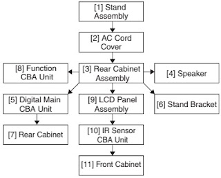
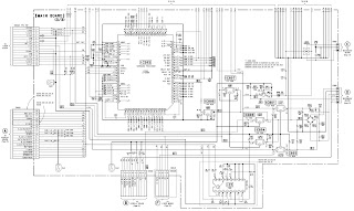
26” TFT TV is a progressive TV control system with built-in de-interlacer and scaler. It uses a 1280*768 panel with 16:9 aspect ratio.
The TV is capable of operation in PAL, SECAM, NTSC (playback) colour standards and multiple transmission standards as B/G, D/K, I/I’, and L/L´ including German and NICAM stereo. Sound system output is supplying 2x8W (10%THD) for stereo 8Ω speakers. The chassis is equipped with many inputs and outputs allowing it to be used as a center of a media system.
The UV1316tuner belongs to the UV 1300 family of tuners, which are designed to meet a wide range of applications. It is a combined VHF, UHF tuner suitable for CCIR systems B/G, H, L, L’, I and I’. The low IF output impedance has been designed for direct drive of a wide variety of SAW filters with sufficient suppression of triple transient.
The TDA9886is an alignment-free multistandard (PAL, SECAM and NTSC) vision and sound IF signal PLL Both devices can be used for TV, VTR, PC and set-top box applications.
VIF amplifier, Tuner and VIF-AGC, VIF-AGC detector, Frequency Phase-Locked Loop (FPLL) detector, VCO and divider, Digital acquisition help and AFC, Video demodulator and amplifier, Sound carrier trap, SIF amplifier, SIF-AGC detector, Single reference QSS mixer, AM demodulator, FM demodulator and acquisition help, Audio amplifier and mute time constant, I²C-bus transceivers and MAD (module address), Internal voltage stabilizer.
The MSP34x1Gfamily of single-chip Multistandard Sound Processors covers the sound processing of all analog TV-Standards worldwide, as well as the NICAM digital sound standards. The full TV sound processing, starting with analog sound IF signal-in, down to processed analog AF-out, is performed on a single chip.
These TV sound processing ICs include versions for processing the multichannel television sound (MTS) signal conforming to the standard recommended by the Broadcast Television Systems Committee (BTSC). The DBX noise reduction, or alternatively, Micronas Noise Reduction (MNR) is performed alignment free. Other processed standards are the Japanese FM-FM multiplex standard (EIA-J) and the FM Stereo Radio standard.
Current ICs have to perform adjustment procedures in order to achieve good stereo separation for BTSC and EIA-J. The MSP34x1G has optimum stereo performance without any adjustments.
In case of three or more external sources are used, the video switch IC TEA6415 is used. The main function of this device is to switch 8 video-input sources on the 6 outputs.
Each output can be switched on only one of each input. On each input an alignment of the lowest level of the signal is made (bottom of sync. top for CVBS or black level for RGB signals).
Each nominal gain between any input and output is 6.5dB.For D2MAC or Chroma signal the alignment is switched off by forcing, with an external resistor bridge, 5VDC on the input. Each input can be used as a normal input or as a MAC or Chroma input (with external Resistor Bridge). All the switching possibilities are changed through the BUS. Driving 75ohm load needs an external resistor. It is possible to have the same input connected to several outputs.
The TPA3002D2is a 9-W (per channel) efficient, Class-D audio amplifier for driving bridged-tied stereo speakers. The TPA3002D2 can drive stereo speakersas low as 8 &. The high efficiency of the TPA3002D2 eliminates the need for external heatsinks when playing music.
The DC voltages required at various parts of the chassis and inverters are provided by an main power supply unit and power interface board. The main power supply unit is designed for 24V and 12V DC supply. Power interface board generates +12V for audio amplifier, 5V and 3.3V stand by voltage and 8V, 12V, 5V and 3V3 supplies for other different parts of the chassis.
An optocoupler is used to control the regulation of line voltage and stand-by power consumption. There is a regulation circuit in secondary side. During the switch on period of the transistor, energy is stored in the transformer. During the switch off period energy is fed to the load via secondary winding. By varying switch-on time of the power transistor, it controls each portion of energy transferred to the second side such that the output voltage remains nearly independent of load variations.
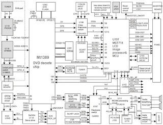
The microprocessor is embedded inside PW181 chip which also handles scaling, frame rate conversion and OSD generation. The on-chip 16-bit microprocessor is a Turbo x86-compatible processor core with on-chip peripherals (timers, interrupt controller, 2-wire serial master/slave interface, UART, I/O ports, and more). Special peripherals such as Infrared (IR) pulse decoders and a digital pulse width modulator (PWM) are also included. There are two independent 2-wire serial master/slave interface modules that can be multiplexed to control up to five 2-wire serial ports. The slave 2-wire interface is designed for HDCP use only (and requires the use of HDCP Image Processors). On-chip RAM of up to 64 Kbytes is available. A complete microprocessor system can be implemented simply by adding external ROM. The on-chip processor can be disabled to allow external processor control of all internal functions.
The Microchip Technology Inc. 24C32A is a 4K x 8 (32K bit) Serial Electrically Erasable PROM. It has been developed for advanced, low power applications such as personal communications or data acquisition. The 24C32A also has a page-write capability of up to 32 bytes of data. The 24C32A is capable of both random and sequential reads up to the 32K boundary. Functional address lines allow up to eight 24C32A devices on the same bus, for up to 256K bits address space. Advanced CMOS technology and broad voltage range make this device ideal for low-power/low-voltage, non-volatile code and data applications.
The TDA1308is an integrated class AB stereo headphone driver contained in a DIP8 plastic package.
The device is fabricated in a 1 mm CMOS process and has been primarily developed for portable digital audio applications.
IC DESCRIPTIONS
TDA9886
TEA6415C
24C32
SAA5264
LM317T
ST24LC21
TLC7733
74LVC257A
74LVC14A
LM1117
IRF7314
IRF7316
MC34063A
LM2576
DS90C385
MSP3411G
TPA3002D
TDA1308
PI5V330
AD9883A
SAA7118E
TPS72501
TSOP1136
PCF8591
PW1231
PW181
SIL151B
SDRAM 4M x 16 (MT48LC4M16A2TG-75)
FLASH
The TDA9885is an alignment-free single standard (without positive modulation) vision and sound IF signal PLL
• 5 V supply voltage
• Gain controlled wide-band Vision Intermediate Frequency (VIF) amplifier (AC-coupled)
• Multistandard true synchronous demodulation with active carrier regeneration (very linear demodulation, good intermodulation figures, reduced harmonics, excellent pulse response)
• Gated phase detector for L/L accent standard
• Fully integrated VIF Voltage Controlled Oscillator (VCO), alignment-free; frequencies switchable for all negative and positive modulated standards via I2C-bus
• Digital acquisition help, VIF frequencies of 33.4, 33.9, 38.0, 38.9, 45.75 and 58.75 MHz
• 4 MHz reference frequency input [signal from Phase-Locked Loop (PLL) tuning system] or operating as crystal oscillator
• VIF Automatic Gain Control (AGC) detector for gain control, operating as peak sync detector for negative modulated signals and as a peak white detector for positive modulated signals
• Precise fully digital Automatic Frequency Control (AFC) detector with 4-bit digital-to-analog converter; AFC bits via I2C -bus readable
• TakeOver Point (TOP) adjustable via I2C-bus or alternatively with potentiometer
• Fully integrated sound carrier trap for 4.5, 5.5, 6.0 and 6.5 MHz, controlled by FM-PLL oscillator
• Sound IF (SIF) input for single reference Quasi Split Sound (QSS) mode (PLL controlled)
• SIF AGC for gain controlled SIF amplifier; single reference QSS mixer able to operate in high performance single reference QSS mode and in intercarrier mode, switchable via I2C-bus
• AM demodulator without extra reference circuit
• Alignment-free selective FM-PLL demodulator with high linearity and low noise
• I2C-bus control for all functions
• I2C-bus transceiver with pin programmable Module Address (MAD)
TEA6415C
The main function of the IC is to switch 8 video input sources on 6 outputs. Each output can be switched on only one of each input. On each input an alignment of the lowest level of the signal is made (bottom of synch. top for CVBS or black level for RGB signals). Each nominal gain between any input and output is 6.5dB. For D2MAC or Chroma signal the alignment is switched off by forcing, with an external resistor bridge, 5 VDC on the input. Each input can be used as a normal input or as a MAC or Chroma input (with external resistor bridge). All the switching possibilities are changed through the BUS. Driving 75Ω load needs an external transistor. It is possible to have the same input connected to
several outputs. The starting configuration upon power on (power supply: 0 to 10V) is undetermined. In this case, 6 words of 16 bits are necessary to determine one configuration. In other case, 1 word of 16 bits is necessary to determine one configuration.
24C32A
The Microchip Technology Inc. 24C32A is a 4K x 8 (32K bit) Serial Electrically Erasable PROM. It has been developed for advanced, low power applications such as personal communications or data acquisition. The 24C32A also has a page-write capability of up to 32 bytes of data. The 24C32A is capable of both random and sequential reads up to the 32K boundary. Functional address lines allow up to eight 24C32A devices on the same bus, for up to 256K bits address space. Advanced CMOS technology and broad voltage range make this device ideal for low-power/low-voltage, non-volatile code and data applications. The 24C32A is available in the standard 8-pin plastic DIP and both 150 mil and 200 mil SOIC packaging.
• Voltage operating range: 4.5V to 5.5V
- Maximum write current 3 mA at 5.5V
- Standby current 1 mA typical at 5.0V
• 2-wire serial interface bus, I2CTM compatible
• 100 kHz and 400 kHz compatibility
• Self-timed ERASE and WRITE cycles
• Power on/off data protection circuitry
• Hardware write protect
• 1,000,000 Erase/Write cycles guaranteed
• 32-byte page or byte write modes available
• Schmitt trigger filtered inputs for noise suppression
• Output slope control to eliminate ground bounce
• 2 ms typical write cycle time, byte or page
• Up to eight devices may be connected to the same bus for up to 256K bits total memory
• Electrostatic discharge protection > 4000V
• Data retention > 200 years
• 8-pin PDIP and SOIC packages
• Temperature ranges
- Commercial (C): 0°C to 70°C
- Industrial (I): -40°C to +85°C
- Automotive (E): -40°C to +125°C
The 24C32A supports a Bi-directional 2-wire bus and data transmission protocol. A device that sends data onto the bus is defined as transmitter, and a device receiving data as receiver. The bus must be controlled by a master device which generates the Serial Clock (SCL), controls the bus access, and generates the START and STOP conditions, while the 24C32A works as slave. Both master and slave can operate as transmitter or receiver but the master device determines which mode is activated
Following features apply to both SAA5264 and SAA5265:
• Complete 625 line teletext decoder in one chip reduces printed circuit board area and cost
• Automatic detection of transmitted fastext links or service information (packet 8/30)
• On-Screen Display (OSD) for user interface menus using teletext and dedicated menu icons
• Video Programming System (VPS) decoding
• Wide Screen Signalling (WSS) decoding
• Pan-European, Cyrillic, Greek/Turkish and French/Arabic character sets in each chip
• High-level command interface via I2C-bus gives easy control with a low software overhead
• High-level command interface is backward compatible to Stand-Alone Fastext And Remote Interface (SAFARI)
• 625 and 525 line display
• RGB interface to standard colour decoder ICs, current source
• Versatile 8-bit open-drain Input/Output (I/O) expander, 5 V tolerant
• Single 12 MHz crystal oscillator
• 3.3 V supply voltage.
SAA5264 features
• Automatic detection of transmitted pages to be selected by page up and page down
• 8 Page fastext decoder
• Table Of Pages (TOP) decoder with Basic Top Table (BTT) and Additional Information Tables (AITs)
• 4 Page user-defined list mode.
The SAA5264 is a single-chip ten page 625-line World System Teletext decoder with a high-level command interface, and is SAFARI compatible.
The device is designed to minimize the overall system cost, due to the high-level command interface offering the benefit of a low software overhead in the TV microcontroller.
The SAA5264 has the following functionality:
• 10 page teletext decoder with OSD, Fastext, TOP, default and list acquisition modes
• Automatic channel installation support
• Closed caption acquisition and display
• Violence Chip (VChip) support.
The LM117/LM217/LM317are monolithic integrated circuit in TO-220, ISOWATT220, TO-3 and D 2 PAK packages intended for use as positive adjustable voltage regulators.
They are designed to supply more than 1.5A of load current with an output voltage adjustable over a 1.2 to 37V range.
The nominal output voltage is selected by means of only a resistive divider, making the device exceptionally easy to use and eliminating the stocking of many fixed regulators.
The ST24LC21 is a 1K bit electrically erasable programmable memory (EEPROM), organized by 8 bits.
This device can operate in two modes: Transmit Only mode and I2C bidirectional mode. When powered, the device is in Transmit Only mode with EEPROM data clocked out from the rising edge of the signal applied on VCLK. The device will switch to the I2C bidirectional mode upon the falling edge of the signal applied on SCL pin. The ST24LC21 can not switch from the I2C bidirectional mode to the Transmit Only mode (except when the power supply is removed). The device operates with a power supply value as low as 2.5V. Both Plastic Dual-in-Line and Plastic Small Outline packages are available.
TLC7733
The TLC77xx family of micropower supply voltage supervisors are designed for reset control, primarily in microcomputer and microprocessor systems.
During power-on, RESET is asserted when VDD reaches 1 V. After minimum VDD (. 2 V) is established, the circuit monitors SENSE voltage and keeps the reset outputs active as long as SENSE voltage (VI(SENSE) remains below the threshold voltage. An internal timer delays return of the output to the inactive state to ensure proper system reset. The delay time, td, is determined by an external capacitor:
td = 2.1 x 10 4 x CT
where
CT is in farads
td is in seconds
The TLC77xx has a fixed SENSE threshold voltage set by an internal voltage divider. When SENSE voltage drops below the threshold voltage, the outputs become active and stay in that state until SENSE voltage returns above threshold voltage and the delay time, td, has expired.
In addition to the power-on-reset and undervoltage-supervisor function, the TLC77xx adds power-down control support for static RAM. When CONTROL is tied to GND, RESET will act as active high. The voltage monitor contains additional logic intended for control of static memories with battery backup during power failure. By driving the chip select (CS) of the memory circuit with the RESET output of the TLC77xx and with the CONTROL driven by the memory bank select signal (CSH1) of the microprocessor the memory circuit is automatically disabled during a power loss. (In this application the TLC77xx power has to be supplied by the battery.)
The TLC77xxQ is characterized for operation over a temperature range of –40°C to 125°C, and the TLC77xxI is characterized for operation over a temperature range of –40°C to 85°C.
The 74LVC257Ais a high-performance, low-power, low-voltage, Si-gate CMOS device and superior to most advanced CMOS compatible TTL families.
Inputs can be driven from either 3.3V or 5.0V devices. In 3-State operation, outputs can handle 5V. This feature allows the use of these devices as translators in a mixed 3.3V/5V environment.
The 74LVC257A is a quad 2-input multiplexer with 3-state outputs, which select 4 bits of data from two sources and are controlled by a common data select input (S). The data inputs from source 0 (1l 0 to 4l 0 ) are selected when input S is LOW and the data inputs from source 1 (1l 1 to 4l 1 ) are selected when S in HIGH. Data appears at the outputs (1Y to 4Y) in true (non-inverting) form from the selected inputs. The 74LVC257A is the logic implementation of a 4-pole, 2-position switch, where the position of the switch is determined by the logic levels applied to S. The outputs are forced to a high impedance OFF-state when OE is HIGH.
The 74LVC14A is a high-performance, low power, low-voltage Si-gate CMOS device and superior to most advanced CMOS compatible TTL families.
Inputs can be driven from either 3.3 V or 5 V devices. This feature allows the use of these devices as translators in a mixed 3.3 V/5 V environment.
The 74LVC14A provides six inverting buffers with Schmitt-trigger action. It is capable of transforming slowly changing input signals into sharply defined, jitter-free output signals.
The LM1117is a series of low dropout voltage regulators with a dropout of 1.2V at 800mA of load current. It has the same pin-out as National Semiconductor’s industry standard LM317. The LM1117 is available in an adjustable version, which can set the output voltage from 1.25V to 13.8V with only two external resistors. In addition, it is also available in five fixed voltages, 1.8V, 2.5V, 2.85V, 3.3V, and 5V.
The LM1117 offers current limiting and thermal shutdown. Its circuit includes a zener trimmed bandgap reference to as-sure output voltage accuracy to within ±1%. The LM1117 series is available in SOT- 223, TO-220, and TO-252 D-PAK packages. A minimum of 10µF tantalum capacitor is required at the output to improve the transient response and stability.
• Available in 1.8V, 2.5V, 2.85V, 3.3V, 5V, and Adjustable Versions
• Space Saving SOT-223 Package
• Current Limiting and Thermal Protection
• Output Current 800mA
• Line Regulation 0.2% (Max)
• Load Regulation 0.4% (Max)
• Temperature Range
— LM1117 0°C to 125°C
— LM1117I -40°C to 125°C
Applications
• 2.85V Model for SCSI-2 Active Termination
• Post Regulator for Switching DC/DC Converter
• High Efficiency Linear Regulators
• Battery Charger
• Battery Powered Instrumentation.
IRF7314- IRF7316
Fifth Generation HEXFETs from International Rectifier utilize advanced processing techniques to achieve extremely low on-resistance per silicon area. This benefit, combined with the fast switching speed and ruggedized device design that HEXFET Power MOSFETs are well known for, provides the designer with an extremely efficient and reliable device for use in a wide variety of applications.
The SO-8 has been modified through a customized leadframe for enhanced thermal characteristics and multiple-die capability making it ideal in a variety of power applications. With these improvements, multiple devices can be used in an application with dramatically reduced board space. The package is designed for vapor phase, infra red, or wave soldering techniques
Step-Up/Down/Inverting Switching Regulators
The MC34063A Series is a monolithic control circuit containing the primary functions required for DC-to-DC converters. These devices consist of an internal temperature compensated reference, comparator, controlled duty cycle oscillator with an active current limit circuit, driver and high current output switch. This series was specifically designed to be incorporated in Step-Down and Step-Up and Voltage-Inverting applications with a minimum number of external components. Refer to Application.
LM2576- 52kHz Simple 3A Buck Regulator
The LM2576 series of monolithic integrated circuits provide all the active functions for a step-down (buck) switching regulator. Fixed versions are available with a 3.3V, 5V, or 12V fixed output. Adjustable versions have an output voltage range from 1.23V to 37V. Both versions are capable of driving a 3A load with excellent line and load regulation. These regulators are simple to use because they require a minimum number of external components and include internal frequency compensation and a fixed-frequency oscillator. The LM2576 series offers a high efficiency replacement for popular three-terminal adjustable linear regulators. It substantially reduces the size of the heat sink, and in many cases no heat sink is required. A standard series of inductors available from several different manufacturers are ideal for use with the LM2576 series. This feature greatly simplifies the design of switch-mode power supplies. The feedback voltage is guaranteed to ±2% tolerance for adjustable versions, and the output voltage is guaranteed to ±3% for fixed versions, within specified input voltages and output load conditions. The oscillator frequency is guaranteed to ±10%. External shutdown is included, featuring less than 200A standby current. The output switch includes cyclebycycle current limiting and thermal shutdown for full protection under fault conditions.
Features
• 3.3V, 5V, 12V, and adjustable output versions
• Voltage over specified line and load conditions:
Fixed version: ±3% max. output voltage
Adjustable version: ±2% max. feedback voltage
• Guaranteed 3A output current
• Wide input voltage range:
4V to 40V.
• Wide output voltage range
1.23V to 37V
• Requires only 4 external components
• 52kHz fixed frequency internal oscillator
• Low power standby mode IQ typically < 200
A
• 80% efficiency (adjustable version typically > 80%)
• Uses readily available standard inductors
• Thermal shutdown and current limit protection
• 100% electrical thermal limit burn-in.
The DS90C385transmitter converts 28 bits of LVCMOS/LVTTL data into four LVDS (Low Voltage Differential Signaling) data streams. A phase-locked transmit clock is transmitted in parallel with the data streams over a fifth LVDS link.
Every cycle of the transmit clock 28 bits of input data are sampled and transmitted. At a transmit clock frequency of 85 MHz, 24 bits of RGB data and 3 bits of LCD timing and control data (FPLINE, FPFRAME, DRDY) are transmitted at a rate of 595 Mbps per LVDS data channel. Using an 85 MHz clock, the data throughput is 297.5 Mbytes/sec. Also available is the DS90C365 that converts 21 bits of LVCMOS/LVTTL data into three LVDS (Low Voltage Differential Signaling) data streams. Both transmitters can be programmed for Rising edge strobe or falling edge strobe through a dedicated pin.
A Rising edge or Falling edge strobe transmitter will interoperate with a Falling edge strobe Receiver (DS90CF386/DS90CF366) without any translation logic.
The DS90C385 is also offered in a 64 ball, 0.8mm fine pitch ball grid array (FBGA) package which provides a 44 % reduction in PCB footprint compared to the TSSOP package. This chipset is an ideal means to solve EMI and cable size problems associated with wide, high-speed TTL interfaces.
Features
• 20 to 85 MHz shift clock support
• Best–in–Class Set & Hold Times on TxINPUTs
• Tx power consumption <130 mW (typ) @85MHz Grayscale
• Tx Power-down mode <200µW (max)
• Supports VGA, SVGA, XGA and Dual Pixel SXGA.
• Narrow bus reduces cable size and cost.
• Up to 2.38 Gbps throughput
• Up to 297.5 Megabytes/sec bandwidth
• 345 mV (typ) swing LVDS devices for low EMI
• PLL requires no external components
• Compatible with TIA/EIA-644 LVDS standard
• Low profile 56-lead or 48-lead TSSOP package
• DS90C385 also available in a 64 ball, 0.8mm fine pitch ball grid array (FBGA) package.
MSP34X1G-MSP3411G Multistandard Sound Processor Family
The MSP 34x1G family of single-chip Multistandard Sound Processors covers the sound processing of all analog TV-Standards worldwide, as well as the NICAM digital sound standards. The full TV sound processing, starting with analog sound IF signal-in, down to processed analog AF-out, is performed on a single chip. Figure shows a simplified functional block diagram of the MSP 34x1G.
The MSP 34x1G has all functions of the MSP 34x0G with the addition of a virtual surround sound feature.
Surround sound can be reproduced to a certain extent with two loudspeakers. The MSP 34x1G includes the Micronas virtualizer algorithm “3D-PANORAMA” which has been approved by the Dolby 1) Laboratories for with the "Virtual Dolby Surround" technology. In addition, the MSP 34x1G includes the “PAN-ORAMA” algorithm.
These TV sound processing ICs include versions for processing the multichannel television sound (MTS) signal conforming to the standard recommended by the Broadcast Television Systems Committee (BTSC). The DBX noise reduction, or alternatively, Micronas Noise Reduction (MNR) is performed alignment free.
Other processed standards are the Japanese FM-FM multiplex standard (EIA-J) and the FM Stereo Radio standard.
Current ICs have to perform adjustment procedures in order to achieve good stereo separation for BTSC and EIA-J. The MSP 34x1G has optimum stereo performance without any adjustments.
The MSP 34x1G has built-in automatic functions: The IC is able to detect the actual sound standard automat-ically (Automatic Standard Detection). Furthermore, pilot levels and identification signals can be evaluated internally with subsequent switching between mono/stereo/bilingual; no I 2 C interaction is necessary (Automatic Sound Selection).
Source Select
I2S bus interface consists of five pins:
1. I2S_DA_IN1, I2S_DA_IN2: For input, four channels (two channels per line, 2*16 bits) per sampling
cycle (32 kHz) are transmitted.
2. I2S _DA_OUT: For output, two channels (2*16 bits) per sampling cycle (32 kHz) are transmitted.
3. I2S _CL: Gives the timing for the transmission of I2S serial data (1.024 MHz).
4. I2S _WS: The I2S _WS word strobe line defines the left and right sample.
• 3D-PANORAMA virtualizer (approved by Dolby Laboratories) with noise generator
• PANORAMA virtualizer algorithm
• Standard Selection with single I2C transmission
• Automatic Sound Selection (mono/stereo/bilingual),
• Automatic Carrier Mute function
• Interrupt output programmable (indicating status change)
• Loudspeaker / Headphone channel with volume, balance, bass, treble, loudness
• AVC: Automatic Volume Correction
• Subwoofer output with programmable low-pass and complementary high-pass filter
• 5-band graphic equalizer for loudspeaker channel
• Spatial effect for loudspeaker channel, processing of all deemphasis filtering
• Two selectable sound IF (SIF) inputs
• Four Stereo SCART (line) inputs, one Mono input; two Stereo SCART outputs
• Complete SCART in/out switching matrix
• Two I2S inputs; one I2S output
• Automatic Standard Detection of terrestrial TV standards
• Demodulation of the BTSC multiplex signal and the SAP channel
• Alignment free digital DBX noise reduction
• BTSC stereo separation (MSP 3441G also EIA-J) significantly better than specification
• SAP and stereo detection for BTSC system
• Demodulation of the FM-Radio multiplex signal.
TPA3002D
The TPA3002D2 is a 9-W (per channel) efficient, Class-D audio amplifier for driving bridged-tied stereo speakers. The TPA3002D2 can drive stereo speakers as low as 8 &. The high efficiency of the TPA3002D2 eliminates the need for external heatsinks when playing music.
FEATURES
- 9-W/Ch Into an 8-Ω Load From 12-V Supply
- Efficient, Class-D Operation Eliminates Heatsinks and Reduces Power Supply Requirements
- 32-Step DC Volume Control From –40 dB to 36 dB
- Line Outputs For External Headphone
- Amplifier With Volume Control
- Regulated 5-V Supply Output for Powering TPA6110A2
- Space-Saving, Thermally-Enhanced PowerPAD Packaging
- Thermal and Short-Circuit Protection.
TDA1308
The TDA1308 is an integrated class AB stereo headphone driver contained in an SO8 or a DIP8 plastic package. The device is fabricated in a 1 mm CMOS process and has been primarily developed for portable digital audio applications. It gets its input from two analog audio outputs (DACA_L and DACA_R) of MSP 34x0G. The gain of the output is adjustable by the feedback resistor between the inputs and outputs.
PI5V330
The PI5V330 is well suited for video applications when switching composite or RGB analog. A picturein-picture application will be described in this brief. The pixel-rate creates video overlays so two or more
pictures can be viewed at the same time. An inexpensive NTSC titler can be implemented by
superimposing the output of a character generator on a standard composite video background.
AD9883A
The AD9883A is a complete 8-bit, 140 MSPS, monolithic analog interface optimized for capturing RGB graphics signals from personal computers and workstations. Its 140 MSPS encode rate capability and full power analog bandwidth of 300 MHz supports resolutions up to SXGA (1280 × 1024 at 75 Hz).
The AD9883A includes a 140 MHz triple ADC with internal 1.25 V reference, a PLL, and programmable gain, offset, and clamp control. The user provides only a 3.3 V power supply, analog input, and Hsync and COAST signals. Three-state CMOS outputs may be powered from 2.5 V to 3.3 V.
The AD9883A’s on-chip PLL generates a pixel clock from the Hsync input. Pixel clock output frequencies range from 12 MHz to140 MHz. PLL clock jitter is 500 ps p-p typical at 140 MSPS. When the COAST signal is presented, the PLL maintains its output frequency in the absence of Hsync. A sampling phase adjustment is provided. Data, Hsync, and clock output phase relationships are maintained. The AD9883A also offers full sync processing for composite sync and sync-on-green applications. A clamp signal is generated internally or may be provided by the user through the CLAMP input pin. This interface is fully programmable via a 2-wire serial interface.
Fabricated in an advanced CMOS process, the AD9883A is provided in a space-saving 80-lead LQFP surface-mount plastic package and is specified over the –40.˚C to +85. ˚C temperature range.
Features
• Industrial Temperature Range Operation
• 140 MSPS Maximum Conversion Rate
• 300 MHz Analog Bandwidth
• 0.5 V to 1.0 V Analog Input Range
• 500 ps p-p PLL Clock Jitter at 110 MSPS
• 3.3 V Power Supply.
• Full Sync Processing
• Sync Detect for Hot Plugging
• Midscale Clamping
• Power-Down Mode
• Low Power: 500 mW Typical
• 4:2:2 Output Format Mode
• APPLICATIONS
• RGB Graphics Processing
• LCD Monitors and Projectors
• Plasma Display Panels
• Scan Converters
• Microdisplays
• Digital TV
SAA7118E
The SAA7118E is a video capture device for applications at the image port of VGA controllers. Philips X-VIP is a new multistandard comb filter video decoder chip with additional component processing, providing high quality, optionally scaled, video.
The SAA7118E is a combination of a four-channel analog preprocessing circuit including source selection, anti-aliasing filter and ADC, an automatic clamp and gain control, a Clock Generation Circuit (CGC), a digital multistandard decoder containing two-dimensional chrominance/luminance separation by an adaptive comb filter and a high performance scaler, including variable horizontal and vertical up and downscaling and a brightness, contrast and saturation control circuit.
It is a highly integrated circuit for desktop video and similar applications. The decoder is based on the principle of line-locked clock decoding and is able to decode the colour of PAL, SECAM and NTSC signals into ITU 601 compatible colour component values. The SAA7118E accepts CVBS or S-video (Y/C) as analog inputs from TV or VCR sources, including weak and distorted signals as well as baseband component signals Y-PB -PR or RGB. An expansion port (X-port) for digital video (bidirectional half duplex, D1 compatible) is also supported to connect to MPEG or video phone codec.
At the so called image port (I-port) the SAA7118E supports 8 or 16-bit wide output data with auxiliary reference data for interfacing to VGA controllers.
The target application for the SAA7118E is to capture and scale video images, to be provided as digital video stream through the image port of a VGA controller, for capture to system memory, or just to provide digital baseband video to any picture improvement processing.
Features
Video acquisition/clock
• Up to sixteen analog CVBS, split as desired (all of the CVBS inputs optionally can be used to convert
e.g. Vestigial Side Band (VSB) signals)
• Up to eight analog Y + C inputs, split as desired
• Up to four analog component inputs, with embedded or separate sync, split as desired
• Four on-chip anti-aliasing filters in front of the Analog-to-Digital Converters (ADCs)
• Automatic Clamp Control (ACC) for CVBS, Y and C (or VSB) and component signals
• Switchable white peak control
• Four 9-bit low noise CMOS ADCs running at twice the oversampling rate (27 MHz)
• Fully programmable static gain or Automatic Gain Control (AGC), matching to the particular signal properties
• On-chip line-locked clock generation in accordance with “ITU 601”
• Requires only one crystal (32.11 or 24.576 MHz) for all standards
• Horizontal and vertical sync detection.
Video decoder
• Digital PLL for synchronization and clock generation from all standards and non-standard video sources e.g. consumer grade VTR
• Automatic detection of any supported colour standard
• Luminance and chrominance signal processing for PAL B, G, D, H, I and N, combination PAL N, PAL
M, NTSC M, NTSC-Japan, NTSC 4.43 and SECAM
• Adaptive 2/4-line comb filter for two dimensional chrominance/luminance separation, also with VTR signals
– Increased luminance and chrominance bandwidth for all PAL and NTSC standards
– Reduced cross colour and cross luminance artefacts
• PAL delay line for correcting PAL phase errors
• Brightness Contrast Saturation (BCS) adjustment, separately for composite and baseband signals
• User programmable sharpness control
• Detection of copy-protected signals according to the macrovision standard, indicating level of protection
• Independent gain and offset adjustment for raw data path.
Component video processing.
• RGB component inputs
• Y-PB -PR component inputs
• Fast blanking between CVBS and synchronous component inputs
• Digital RGB to Y-CB -CR matrix.
Video scaler
• Horizontal and vertical downscaling and upscaling to randomly sized windows
• Horizontal and vertical scaling range: variable zoom to 1/64 (icon) (note: H and V zoom are restricted by the transfer data rates)
• Anti-alias and accumulating filter for horizontal scaling
• Vertical scaling with linear phase interpolation and accumulating filter for anti-aliasing (6-bit phase accuracy)
• Horizontal phase correct up and downscaling for improved signal quality of scaled data, especially for compression and video phone applications, with 6-bit phase accuracy (1.2 ns step width)
• Two independent programming sets for scaler part, to define two ‘ranges’ per field or sequences over frames
• Fieldwise switching between decoder part and expansion port (X-port) input
• Brightness, contrast and saturation controls for scaled outputs.
Vertical Blanking Interval (VBI) data decoder and slicer
• Versatile VBI-data decoder, slicer, clock regeneration and byte synchronization e.g. for World Standard Teletext (WST), North-American Broadcast Text System (NABTS), close caption, Wide Screen Signalling (WSS) etc.
Audio clock generation
• Generation of a field-locked audio master clock to support a constant number of audio clocks per video field
• Generation of an audio serial and left/right (channel)
Digital I/O interfaces
• Real-time signal port (R port), inclusive continuous line-locked reference clock and real-time status information supporting RTC level 3.1 (refer to document “RTC Functional Specification” for details)
• Bidirectional expansion port (X-port) with half duplex functionality (D1), 8-bit Y-CB -CR
– Output from decoder part, real-time and unscaled
– Input to scaler part, e.g. video from MPEG decoder (extension to 16-bit possible)
• Video image port (I-port) configurable for 8-bit data (extension to 16-bit possible) in master mode (own clock), or slave mode (external clock), with auxiliary timing and handshake signals
• Discontinuous data streams supported
• 32-word x 4-byte FIFO register for video output data
• 28-word x 4-byte FIFO register for decoded VBI-data output
• Scaled 4 :2 :2, 4 :1 :1, 4 :2 :0, 4 :1 :0 Y-CB -CR output
• Scaled 8-bit luminance only and raw CVBS data output
• Sliced, decoded VBI-data output.
Miscellaneous
• Power-on control
• 5 V tolerant digital inputs and I/O ports
• Software controlled power saving standby modes supported
• Programming via serial I2C-bus, full read back ability by an external controller, bit rate up to 400 kbits/s
• Boundary scan test circuit complies with the “IEEE Std. 1149.b1 - 1994”
• BGA156 package.
The TPS725xxfamily of 1-A low-dropout (LDO) linear regulators has fixed voltage options available that are commonly used to power the latest DSPs, FPGAs, and microcontrollers. An adjustable option ranging from 1.22 V to 5.5 V is also available. The integrated supervisory circuitry provides an active low RESET signal when the output falls out of regulation. The no capacitor/any capacitor feature allows the customer to tailor output transient performance as needed. Therefore, compared to other regulators capable of providing the same output current, this family of regulators can provide a stand alone power supply solution or a post regulator for a switch mode power supply.
These regulators are ideal for higher current applications. The family operates over a wide range of input voltages (1.8 V to 6 V) and has very low dropout (170 mV at 1-A).
Ground current is typically 210 µA at full load and drops to less than 80 µA at no load. Standby current is less than 1 µA.
Each regulator option is available in either a SOT223–5, D (TPS72501 only), or DDPAK package. With a low input voltage and properly heatsinked package, the regulator dissipates more power and achieves higher efficiencies than similar regulators requiring 2.5 V or more minimum input voltage and higher quiescent currents. These features make it a viable power supply solution for portable, battery powered equipment.
Although an output capacitor is not required for stability, transient response and output noise are improved with a 10-µF output capacitor.
Unlike some regulators that have a minimum current requirement, the TPS725 family is stable with no output load current. The low noise capability of this family, coupled with its high current operation and ease of power dissipation, make it ideal for telecom boards, modem banks, and other noise sensitive applications.
Features
• 1-A Output Current
• Available in 1.5-V, 1.6-V, 1.8-V, 2.5-V Fixed-Output and Adjustable Versions (1.2-V to 5.5-V)
• Input Voltage Down to 1.8 V
• Low 170-mV Dropout Voltage at 1 A (TPS72525)
• Stable With Any Type/Value Output Capacitor
• Integrated Supervisor (SVS) With 50-ms RESET Delay Time
• Low 210-µA Ground Current at Full Load (TPS72525)
• Less than 1-µA Standby Current
• ±2% Output Voltage Tolerance Over Line, Load, and Temperature (–40C to 125C)
• Integrated UVLO
• Thermal and Overcurrent Protection
• 5-Lead SOT223–5 or DDPAK and 8–Pin SOP (TPS72501 only) Surface Mount Package.
PCF8591
The PCF8591 is a single-chip, single-supply low power 8-bit CMOS data acquisition device with four analog inputs, one analog output and a serial I2C-bus interface.
Three address pins A0, A1 and A2 are used for programming the hardware address, allowing the use of up to eight devices connected to the I2C-bus without additional hardware. Address, control and data to and from the device are transferred serially via the two-line bidirectional I2C-bus.
The functions of the device include analog input multiplexing, on-chip track and hold function, 8-bit analog-to-digital conversion and an 8-bit digital-to-analog conversion. The maximum conversion rate is given by the maximum speed of the I2C-bus.
Features
• Single power supply
• Operating supply voltage 2.5 V to 6 V
• Low standby current
• Serial input/output via I 2 C-bus
• Address by 3 hardware address pins
• Sampling rate given by I 2 C-bus speed
• 4 analog inputs programmable as single-ended or differential inputs
• Auto-incremented channel selection
• Analog voltage range from VSS to VDD
• On-chip track and hold circuit.
• 8-bit successive approximation A/D conversion
• Multiplying DAC with one analog output.
PW1231
The PW1231 is a high-quality, digital video signal processor that incorporates Pixelworks’ patented deinterlacing, scaling, and video enhancement algorithms. The PW1231 accepts industry-standard video formats and resolutions, and converts the input into any desired output format.The video algorithms are highly efficient, providing excellent quality video.
The PW1231 Video SignalProcessor combines many functions into a single device, including memory controller, auto-configuration, and others. This high level of integration enables simple, flexible, costeffective solutions featuring fewer required components.
PW181
The PW181 ImageProcessor is a highly integrated “system-on-a-chip” that interfaces computer graphics and video inputs in virtually any format to a fixed-frequency flat panel display.
Computer and video images from NTSC/PAL to WUXGA at virtually any refresh rate can be resized to fit on a fixed-frequency target display device with any resolution up to WUXGA. Video data from 4:3 aspect ratio NTSC or PAL and 16:9 aspect ratio HDTV or SDTV is supported. Multi-region, nonlinear scaling allows these inputs to be resized optimally for the native resolution of the display.
Advanced scaling techniques are supported, such as format conversion using multiple programmable regions. Three independent image scalers coupled with frame locking circuitry and dual programmable color lookup tables create sharp images in multiple windows, without user intervention.
Embedded SDRAM frame buffers and memory controllers perform frame rate conversion and enhanced video processing completely on-chip. A separate memory is dedicated to storage of onscreen display images and CPU general purpose use.  Advanced video processing techniques are supported using the internal frame buffer, including motion adaptive, temporal deinterlacing with film mode detection. When used in combination with the new third-generation scaler, this advanced video processing technology delivers the highest quality video for advanced displays.
Both input ports support integrated DVI 1.0 content protection using standard DVI receivers.
A new advanced OSD Generator with more colors and larger sizes supports more demanding OSD applications, such as on-screen programming guides. When coupled with the new, faster, integrated microprocessor, this OSD Generator supports advanced OSD animation techniques.
Programmable features include the user interface, custom start-up screen, all automatic imaging features, and special screen effects.
SIL151B
The SiI 151B receiver uses PanelLink Digital technology to support high-resolution displays up to SXGA (25-112MHz). This receiver supports up to true color panels (24 bit/pixel, 16M colors) with both one and two pixels per clock.
All PanelLink products are designed on a scaleable CMOS architecture, ensuring support for future performance enhancements while maintaining the same logical interface. System designers can be assured that the interface will be stable through a number of technology and performance generations.
PanelLink Digital technology simplifies PC and display interface design by resolving many of the system level issues associated with high-speed mixed signal design, providing the system designer with a digital interface solution that is quicker to market and lower in cost.
Features
• Low Power Operation: 201mA max. current consumption at 3.3V core operation
• Time staggered data output for reduced ground bounce and lower EMI
• Sync Detect feature for Plug & Display iMHot Plugginglo
• Cable Distance Support: over 5m with twisted-pair, fiber-optics ready
• Compliant with DVI 1.0 (DVI is backwards compatible with VESA ® P&D TM and DFP)
• HSYNC de-jitter circuitry enables stable operation even when HSYNC contains jitter
• Low power standby mode
• Automatic entry into standby mode with clock detect circuitry
• Standard and Pb-free packages.
SDRAM 4M x 16 (MT48LC4M16A2TG-75)
The Micron ® 64Mb SDRAM is a high-speed CMOS, dynamic random-access memory containing 67,108,864 bits. It is internally configured as a quad-bank DRAM with a synchronous interface (all signals are registered on the positive edge of the clock signal, CLK). Each of the x4’s 16,777,216-bit banks is orga-nized as 4,096 rows by 1,024 columns by 4 bits. Each of the x8’s 16,777,216-bit banks is organized as 4,096 rows by 512 columns by 8 bits. Each of the x16’s 16,777,216- bit banks is organized as 4,096 rows by 256 columns by 16 bits.
Accesses begin with the registration of an ACTIVE command, which is then followed by a READ or WRITE command. The address bits registered coincident with the ACTIVE command are used to select the bank and row to be
accessed (BA0, BA1 select the bank; A0-A11 select the row). The address bits registered coincident with the READ or WRITE command are used to select the starting column location for the burst access.
The SDRAM provides for programmable READ or WRITE burst lengths of 1, 2, 4, or 8 locations, or the full page, with a burst terminate option. An auto precharge function may be enabled to provide a selftimed row precharge that is initiated at the end of the burst sequence.
The 64Mb SDRAM uses an internal pipelined architecture to achieve high-speed operation. This architecture is compatible with the 2n rule of prefetch architectures, but it also allows the column address to be changed on every clock cycle to achieve a high-speed, fully random access. Precharging one bank while accessing one of the other three banks will hide the precharge cycles and provide seamless, high-speed, random-access operation.
The 64Mb SDRAM is designed to operate in 3.3V memory systems. An auto refresh mode is provided, along with a power-saving, power-down mode. All inputs and outputs are LVTTL-compatible.
SDRAMs offer substantial advances in DRAM operating performance, including the ability to synchronously burst data at a high data rate with automatic column-address generation, the ability to interleave between internal banks in order to hide precharge time and the capability to randomly change column addresses on each clock cycle during a burst access.
Features
• PC66-, PC100-, and PC133-compliant
• Fully synchronous; all signals registered on positive edge of system clock
• Internal pipelined operation; column address can be changed every clock cycle
• Internal banks for hiding row access/precharge
• Programmable burst lengths: 1, 2, 4, 8, or full page
• Auto Precharge, includes CONCURRENT AUTO PRECHARGE, and Auto Refresh Modes
• Self Refresh Modes: standard and low power
• 64ms, 4,096-cycle refresh
• LVTTL-compatible inputs and outputs
• Single +3.3V ±0.3V power supply.
FLASH 16Mbit
The M29W160E is a 16 Mbit (2Mb x8 or 1Mb x16) non-volatile memory that can be read, erased and reprogrammed. These operations can be performed using a single low voltage (2.7 to 3.6V) supply. On power-up the memory defaults to its Read mode where it can be read in the same way as a ROM or EPROM. The memory is divided into blocks that can be erased independently so it is possible to preserve valid data while old data is erased. Each block can be protected independently to prevent accidental Program or Erase commands from modifying the memory. Program and Erase commands are written to the Command Interface of the memory. An on-chip Program/Erase Controller
simplifies the process of programming or erasing the memory by taking care of all of the special operations that are required to update the memory contents. The end of a program or erase operation can be detected and any error conditions identified. The command set required to control the memory is consistent with JEDEC standards. The blocks in the memory are asymmetrically arranged, The 16 KByte Boot Block can be used for small initialization code to start the microprocessor, the two 8 Kbyte Parameter Blocks can be used for parameter storage and the remaining 32K is a small Main Block where the application may be stored. Chip Enable, Output Enable and Write Enable signals
control the bus operation of the memory. They allow simple connection to most microprocessors, often without additional logic. The memory is offered TSOP48 (12 x 20mm) and TFBGA48 (0.8mm pitch) packages. The memory is supplied with all the bits erased (set to ’1’).
FEATURES SUMMARY
■ SUPPLY VOLTAGE
– VCC = 2.7V to 3.6V for Program, Erase and Read
■ ACCESS TIMES: 70, 90ns
■ PROGRAMMING TIME
– 10µs per Byte/Word typical
■ 35 MEMORY BLOCKS
– 1 Boot Block (Top or Bottom Location)
– 2 Parameter and 32 Main Blocks
■ PROGRAM/ERASE CONTROLLER
– Embedded Byte/Word Program algorithms
■ ERASE SUSPEND and RESUME MODES
– Read and Program another Block during Erase Suspend
■ UNLOCK BYPASS PROGRAM COMMAND
– Faster Production/Batch Programming
■ TEMPORARY BLOCK UNPROTECTION MODE
■ COMMON FLASH INTERFACE
– 64 bit Security Code
■ LOW POWER CONSUMPTION
– Standby and Automatic Standby
■ 100,000 PROGRAM/ERASE CYCLES per BLOCK
■ ELECTRONIC SIGNATURE
– Manufacturer Code: 0020h
– Top Device Code M29W160ET: 22C4h
– Bottom Device Code M29W160EB: 2249h.
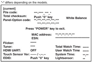
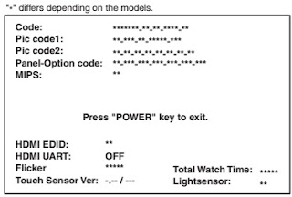
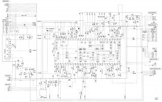
See the next post to  see the service mode details, and the circuit diagram of this LCD TV

How to enter service mode – Hitachi 26LD6200, service mode adjustments, schematic

$
0
0

Applicable to Hitachi 26LD6200, 32LD6200, 26LD6200IT
SERVICE MENU SETTINGS
All system, geometry and white balance alignments are performed in production service mode. Before starting the production mode alignments, make sure that all manual adjustments are done correctly. To start production mode alignments enter the MENU by pressing “M” button and then press the digits 4, 7, 2 and 5 respectively. The following menu appears on the screen.
There are 3 submenu in service menu. These are display, calibration and deinterlacer menus. Press “◄/►” buttons to select a menu title and then “▲/▼” buttons to select a menu item and “◄/►” or “OK” buttons to set the menu item to the desired option. To exit the service menu press “M” button.
Entire service menu parameters of Plasma TV are listed below.
Blank color
By pressing c/d button, select blank color. Press e/f button to set the blank color. The options are:
black, red, green and blue.
panel
Displays panel resolution
power on time
Displays total working time of the set
backlight on time
Displays total backlight on time of the set.
Scart prescale
By pressing c/d button, select scart prescaler. Press e/f button to set the scart prescaler. Scart prescale can be adjusted between 0 and 127.
Nicam prescale
By pressing c/d button, select nicam prescaler. Press e/f button to set the nicam prescaler. Nicam prescale can be adjusted between 0 and 127.
fm/am prescale
By pressing c/d button, select fm/am prescaler. Press e/f button to set the fm/am prescaler. Fm/am prescale can be adjusted between 0 and 127.
subwoofer corner
By pressing c/d button, select subwoofer corner. Press e/f button to set the subwoofer corner.
Subwoofer corner can be adjusted between 0 and 7.
subwoofer level
By pressing c/d button, select subwoofer level. Press e/f button to set the subwoofer level.
Subwoofer level can be adjusted between 0 and 32.
agc adjustment
Adjustment for automatic gain control of tuner. By pressing c/d button, select agc adjustment. Press Up/Dn  button to set the agc adjustment. Agc adjustment can be adjusted between 0 and 31.
calibration menu
By pressing “◄/►” buttons select the second icon. calibration menu appears on the screen.
color temp
By pressing up/dn button, select color temp. Press L/R button to set the color temperature. The options are: 5500K, 6500K, 7500K, 9300K and user.
user color temp
By pressing up/dn button, select user color temp. Press the Right button to increase the user color temperature. Press Left button to decrease the user color temperature. User color temperature can be adjusted between 5000K and 9300K.
video format
By pressing up/dn button, select video format. Press Left/Right button to set the video format. The options are: auto, ntsc, pal, secam and NTSC japan.
color space
Displays the current color space used. RGB, YPbPr SMPTE240, YPbPr REC709 and YCbCr REC601.
test pattern
By pressing Up/Dn button, select test pattern. Press Left/Right  button to set the test pattern. The options are:
none, solid color and vert bars.
color components
By pressing Up/Dn button, select color components. Press Left/Right button to set the color components.
The options are: all, red, green and blue.
solid field level
By pressing Up/Dn button, select solid field level. Press Right button to increase or Left button to decrease the solid field level. Solid field level can be adjusted between 0 and 64.
adc calibration
Not used for this model.
initial APS
By pressing Up/Dn button, select initial APS. Initial aps is selected on or off. If initial aps is wanted on startup, this item should be made on.
factory reset
By pressing Up/Dn button, select factory reset. Press “OK” button to return to the factory setting values.
deinterlacer menu
By pressing “◄/►” buttons select the third icon. deinterlacer menu appears on the screen
blank expansion
By pressing Up/Dn button, select blank expansion. Blank expantion can be set to on or off by pressing Left/Right button.
dcti
Digital colour transition improvement: By pressing Up/Dn button, select dcti. DCTI can be adjusted between 0 and 255 by pressing Left/Right  button.
dlti
Digitial luma transition improvement: By pressing c/d button, select dlti. DLTI can be adjusted between 0 and 255 by pressing e/f button.
luminance peaking
By pressing Up/Dn button, select luminance peaking. Luminance peaking can be set to on or off by pressing Left/Right button.
film mode
By pressing Up/Dnbutton, select film mode. Film mode speed can be set to on or off by pressing Left/Right button.
film mode speed
By pressing Up/Dn button, select film mode speed. Film mode speed can be set to 0, 1, 2 or 3 by
pressing Left/Right button.
vof
video on film. By pressing Up/Dn button, select vof. VOF can be set to on or off by pressing Left/Right button.
bad cut
By pressing Up/Dn button, select vof. Bad cut can be set to on or off by pressing Left/Right button.
nr threshold
By pressing Up/Dn button, select nr threshold. Nr threshold can be set to low or high by pressing Left/Right button.
noise reduction
By pressing Up/Dn  button, select noise reduction. Noise reduction can be adjusted between 0 and 255 by pressing Left/Right button.
lai level
By pressing Up/Dn button, select lai level. Lai level can be set to 0, 1 or 2 by pressing Left/Right button.
sharpness
By pressing Up/Dn button, select sharpness. Sharpness can be adjusted between 0 and 255 by pressingLeft/Right  button.
sparkle
By pressing Up/Dn button, select sparkle. Sparkle can be adjusted between 0 and 255 by pressing Left/Right button.
Factory reset values
Schematic


Sony STRDE245-how to enter the factory mode, adjustments, schematic

$
0
0

Sony FM Stereo FM-AM Receiver - STR-DE245/DE345STR-DE245/DE345
Australian Model – STRDE245 – STRDE345
SOFTWARE VERSION DISPLAY MODE
* The software version is displayed.STRDE245/STRDE345
US, Canadian and Chinese Models
STRDE345
* Procedure:
While depressing the TUNER and the VIDEO buttons simultaneously, press the power [Power] button to turn on the main power. The model name, destination and the software version are displayed.
FLUORESCENT INDICATOR TUBE TEST MODE
* All fluorescent segments are tested. When this test is activated, all segments turn on at the same time, then each segment turns on one after another.
* Procedure:
While depressing the TV/SAT and the CD buttons simultaneously, press the power [Power]  button to turn on the main power.
FLUORESCENT INDICATOR TUBE TEST MODE
* All fluorescent segments are tested. When this test is activated, all segments turn on at the same time, then each segment turns on one after another.
* Procedure:
While depressing the TV/SAT and the CD buttons simultaneously, press the power [Power] button to turn on the main power.
Press the VIDEO button, confirm display
BASS BOOST, MUTING, SET UP and NAME LED turn on.
Press the VIDEO button, confirm display [for the second time]
SOUND CONTROL LEVEL, SOUND CONTROL SUR and SOUND FIELD LED turn on.

Press the VIDEO button, confirm display 

BASS BOOST, MUTING, SET UP and NAME LED turn on.

Press the VIDEO button, All segments turn off.


SOUND CONTROL LEVEL, SOUND CONTROL SUR and SOUND FIELD LED turn on.

Press the VIDEO button, All segments turn off

Every pressing of the VIDEO button turns on each segment one after another in the following order.

(Not only the VIDEO button, but also the other buttons such as
TV/SAT, MD/TAPE, CD, TUNER can be used.)
FACTORY SET MODE
* All preset contents are reset to the default setting.
* Procedure:
While depressing the VIDEO and the CD buttons simultaneously, press the power [Power] button to turn on the main power. The message FACTORY appears and the present contents are reset to the default values.
ALL CLEAR MODE
* All preset contents are cleared when this mode is activated. Use this mode before returning the product to clients upon completion of repair.
* Procedure:
While depressing the TUNER and the MD/TAPE buttons simultaneously, press the power [Power] button to turn on the main power. The message INITIAL appears and initialization is performed.
SURROUND CLEAR MODE
* The preset sound field is cleared when this mode is activated.
Use this mode before returning the product to clients upon completion of repair.
* Procedure:
While depressing the SOUND FIELD ON/OFF button, press the power [Power] button to turn on the main power. The message SURR CLR appears and initialization is performed.
 
AM CHANNEL STEP 9 kHz/10 kHz
SELECTION MODE
* Either the 9 kHz step or 10 kHz step can be selected for the AM channel step.
* Procedure:
Set the FUNCTION to AM. Turn off the main power.
While depressing the TUNING+ button or the PRESET+ button, press the power [Power] button to turn on the main power. Either the message AM 9 k STEP or AM 10 k STEP appears. Select the desired step.
* For US/Canadian/E model only
KEY CHECK MODE
* Button check
* Procedure:
While depressing the MD/TAPE and the CD buttons simultaneously, press the power [Power] button to turn on the main power.
“RES 36 KEY” appears.
Every pressing of any button other than [Power] and SPEAKERS counts down the buttons. The buttons which are already counted once are not counted again. When all buttons are pressed “RES 00 KEY” appears.
When MASTER VOLUME is rotated in clockwise direction, “VOL MIN”, “VOL 1” to “VOL 30”, “VOL MAX” appears.
Main board
Schematic
Display board schematic

BOSE LIFESTYLE - T10 - HOME THEATER SYSTEM - Disassembling procedure – Step by Step instruction

$
0
0

1. Top Cover Assembly Removal
1.1 Remove the 6 screws located on the bottom of the console as indicated.
1.2 Lift off the top cover assembly.
Important Note: When replacing the top cover, press down on the top cover before tightening the screws. Do this to avoid the screw having to take up the pressure of the cover shield against the base shield. Failure to do so could result in a stripped screw.

2. AUX/Tuner PCB Removal
2.1 Remove the two screws indicated.
2.2 Remove the four cables from the AUX PCB connectors.
2.3 Remove the two screws securing the J700 connector block to the rear panel.
2.4 Lift up the AUX PCB.
Important Note: When replacing the AUX PCB, align the J700 connector block to the rear panel before securing it with the screws. Do not allow the rear panel to touch the AM/FM connector shields. Center the PCB screw holes to the screws bosses in the base.

3. Zone 2 PCB Removal (AV35 Only)
3.2 Remove the three screws securing the RCA block to the rear panel.
3.3 Remove the three screws securing the Zone 2 PCB bracket to the rear panel.
3.4 Lift out the Zone 2 PCB.


4. Main PCB Removal
4.1 Perform procedure 3 first
4.2 Remove the three screws indicated.
4.3 Remove the five screws securing the Main PCB connector blocks to the rear panel.
4.4 Lift out the Zone 2 PCB bracket.
4.5 Disconnect the three cables from the Main PCB.
4.6 Release the two latches indicated.
4.7 Lift out the Main PCB
Important Note: When replacing the Main PCB, align the connector blocks to the rear panel before securing it with the screws. Align the PCB to the alignment holes provided in the base.

5. IR Blaster PCB Removal
5.1 Remove the cable from the IR blaster PCB.
5.1 Press on the latch indicated and lift up on the
right side of the PCB.


6. Front AV PCB Removal
6.1 Remove the two screws indicated.
6.2 Remove the cable from the AV PCB.
6.3 While pressing on the two latches toward the rear of the PCB, lift up on the rear of the PCB.

7. Button PCB Removal
7.1 Remove the two screws indicated.
7.2 Remove the
7.3 Lift up on the right side of the button assembly and rotate toward the left to release the latches.

8. End Cap Removal
8.1 The latches on the end cap need to be released from the console base. See Figure.

8.2 Turn the console upside down.
8.3 Press a flat blade screwdriver in-between the console base and the front of the end cap. Once the screwdriver is between the end cap and base, rotate the screw driver downward to loosen the front end cap latch. See Figure .


8.4 Press a flat blade screwdriver in-between the console base and the rear of the end cap. Once the screwdriver is between the end cap and base, rotate the screw driver downward to loosen the rear end cap latch. See Figure .

8.5 Once the both ends of the end cap are released, slide off the end cap.
9. End Cap Replacement
9.1 With the console right side up, slide the end cap onto the side of the base. Be sure to engage all end cap latches into the base.
9.2 Press downward on the end cap until the flat edges of the end cap alignment locator is flush with the bass.

9. Door Assembly Removal
9.1 Remove the three screws from the right hinge assembly as indicted. Lift off the hinge assembly.
9.2 Remove the two screws from the left hinge assembly as indicated.
9.3 Open the door slightly. Slide the left hinge assembly toward the right to disengage it from the door hinge pin, leaving the spring in the hinge assembly.
9.4 Slide off the striker door clip.
9.5 Slide out the door.

BBK LD1506SI-2- LD1506SI-3- LT1500S-2- LT1500S-3, LT2000S- LD1906SI- LT1900S troubleshooting, SMPS schematic

$
0
0

LD2006SI-2 is a LCD TV with multiple functions. It adopts MST718 as main chip (MST718 has built-in MCU and video processor). Video main board of this machine adopts 21903-X series PCB (only small changes are made in PCB board numbers and service manual of LD2006SI-2 adopts the video main board of 21903-5). This PCB integrates the circuit of DVD function and DVB function on video main board. This PCB is widely used and there are many derived machines. Now we will introduce functions and machine structure of several derived machines one by one.
LT2000S model
Based on LD2006SI-2, LT2000S cancels DVD/card read function, but other circuit and components are totally the same with those of LD2006SI-2. Compared with LD2006SI-2 on the aspect of composition of the player, LT2000S has no PCB components of USB board /DVD button board/video main board (DVD function circuit is absent).
LD1506SI-2 model
LD1506SI-2 is a 15” LCD TV, which changes display screen to 15” LCD TFT screen on the basis of LD2006SI-2. According to parameters requirements, drive means and inverter components are changed. Differences on video main board: 1) LD1506SI-2 adopts LVDS output means, while LD2006SI-2 adopts TTL output means, so the peripheral circuit of LCD drive output part on MST718 has slight difference; 2) 15” screen adopts 5V power supply, so IC702 is added to act as voltage stabilizing IC; 20” screen adopts 12V power supply, so there is no need to add voltage stabilizing IC; 3) LD1506SI-2 adds VGA input circuit according to design requirements to make the machine use as display; 4) LD1506SI-2 adopts adapter (AK083-3) to supply power, while LD2006SI adopts internal power board to supply power, so power input end is added on video main board.
LD1506SI-3 model
LD1506SI-3 changes display screen and MST718 ob the basis of LD1506SI-2. The main differences are: display screen is changed to BOEHT150X02-100 15” TFT screen; main IC MST718BE is changed to MST718BU PQFP; other parts are totally the same.
LT1500S-2 model
LT1500S-2 cancels DVD function on the basis of LD1506SI-2 but other parts are totally the same.
LT1500S-3 model
LT1500S-3 changes display screen and MST718 on the basis of LT1500S-2. The main differences are: display screen is changed to BOEHT150X02-100 15” TFT screen; main IC MST718BE is changed to MST718BU PQFP; other parts are totally the same.
LD1906SI
LD1906SI changes display screen to 19” TFT screen on the basis of LD1506SI-2. Because of this, boost components has alteration, that is, boost components are changed to INV403 (working principle is the same with INV607 and you may refer to “LT2002S Service Manual). Display screen drive adopts LVDS input method and other circuits' working principle is totally the same with that of LD2006SI-2.
LT1900S model
LT1900S cancels DVD function on the basis of LD1906SI and other parts are totally the same with those of LD1906SI.
Parental control settings
set-up of age restrictions to prevent children from seeing undesirable discs.
Options: Any, Kid, G,PG, PG-13, PGR, R,NC-17
Change password: set-up of a four-digit password to change the level of age restrictions.
[Default option: 7890]
Initial setup
Press the RIGHT key to enter the initial settings menu, then select the desired item using the cursor buttons and press OK key for confirmation.
While being in this menu section, you cannot return to the previous level by pressing the LEFT key.
LD2006SI is a 20” LCD_TV with multiple functions, such as DVD playing and USB reading function.
Electronic scheme of TV part adopts 20” TFT display screen+inverter components (INV604)+MST718+STV8216 +TDA7266P+ tuner JS -6H2/T121. MST718 includes MCU/video A/D converter/LCD image processing circuit. DVD part electronic scheme adopts MT1389HD+64M SDRAM+16M FLASH+D5954. HD62 loader can smoothly read MPEG4/MP3/CD/DVD format discs and decode chip MT1389HD may support USB and card read function.
Block diagram [common]
System control circuit is mainly composed of reset circuit, clock circuit t, serial/parallel conversion circuit, software program, EEPROM and MCU (MST718 is built inside). The built-in MCU of MST718 is mainly responsible for the coordination and control of system of the player. This MCU is connected with a 2M ROM externally, which is used to store software and control function of the player. Since I/O port of MST718 is limited, a serial/parallel conversion circuit (CD4094)is added to extend I/O port. Functions may be adjusted through software. MST718 is connected with a 32k EEPROM externally, used to store user-set information.
System control circuit of the player is composed of the built-in MCU of MST718 and software Program. Machine power on: after 12V power is being rectified by U503, +5V power outputs to provide for system control circuit. The reset circuit of system control circuit begins to reset MST718, the red indicator light on remote control receiving board is on under the control of STBY signal (high level), and this means machine enters standby state.
The process from standby state to power on state: after pressing POWER button on panel or wake code on remote controller, pin 57 of MST718 changes from high level to low level, pin STBY outputs a low level signal to make Q117 cutoff, /STBY skips to high level, STBY is divided to 3 parts: +5V power control circuit composed of Q3/U506; +12V power control circuit composed of Q117/U511 and standby indication circuit on remote control receiving board. Power supply of machine is normal, MST718 begins to output reset and other control signal  to reset and control circuit of other module to make machine enter normal working state.
The process from working state to standby state: when machine is in power-on state, after pressing POWER button on panel or wake code on remote controller again, machine enters from power on to standby, now pin 57 of MST718 outputs high level, /STBY pin output low level, +5V power and +12V power of machine are cut off and machine enters standby state.
NICAM: the core technoloy of “NICAM” is the NICAM728 technology developed by BBC. Besides transmitting TV image and simulating mono-channel signal, NICAM TV broadcasting system also transmits dual-channel digital coding sound signal. NICAM is famous for clear treble and deep bass with the sound quality close to listening to CD disk directly. In the aspect of SNR, dynamic range and channel separation index, NICAM is far better than the current FM accompany. As TV accompany, NICAM applies 3 kinds of working mode currently: 1) Bilingual mode: NICAM transmits dual-channel digital sound relevant or irrelevant to the current program and transmits 3-channel sound signal together with The original FM analog accompany, which are suitable for multi-language areas; 2) Stereo mode: two digital channels of NICAM transmit left and right channel sound signals of stereo separately, and the original FM analog accompany only transmits mixed sound signals of 2 channels to be compatible with TV set without NICAM function; 3) Mon0-channel mode: two channels of NICAM transmit one channel sound signals and one channel data signal, which is equal to providing 3-channel signals together with the original TV analog accompany.
Power-on mute: after power on, machine enters from standby to power on. Because of R28, pin 11 of TDA726P is low level, now ONMUTE pin of Cd4094 outputs high level signal, OUTMUTE is high level, ,Q113/Q112/Q119 is saturated on, machine enters mute state to realize power-on mute effect. After machine starts up, ONMUTE switches to low level, Q113/Q112/Q119 cuts off to make pin 6 of TDA7266 high level, TDA7266 enters non-mute mode, the player has sound output and power-on mute fulfills.
Power-off mute: when machines enters standby mode from working state, ONMUTE pin outputs high level, OUTMUTE pin is high level signal, TDA7266 enters mute state.
Power failure mute: when power of machine is switched off, Ce151 has been fully charged when power on, after machine power switches off, Ce151 discharges through Q118/D121 to make Q119 connected, now pin 6 of TDA7266 is low level to realize power-off mute function.
When user use remote controller to mute the machine, MUTE pin outputs high level signal to make Q119 saturated on, pin 6 of TDA7266 is low level and TDA7266 enters mute mode.
Power circuit
Working principle: after AC power is being rectified and filtered through power board, 12V power outputs. This power is inputted to voltage stabilizing circuit of video main board through socket Cn6 for voltage stabilizing. The power outputted after being voltage stabilized is working power of each circuit.
Voltage stabilizing circuit on video main board is divided to 3 parts: 1) +5VEXT outputted after being voltage stabilized by Ic503 is mainly supplied for system control circuit; 2) +5V power outputted after being voltage stabilized by is mainly supplied for DVD/DVB circuit; 3) +12V voltage stabilizing and control circuit supply working voltage for rear audio circuit.
Working principle:
+5VEXT voltage stabilizing circuit: after the AC power inputted externally is being rectified/filtered through power board, +12V power inputs to main video board. +12V power is divided to multi-group power supply. One group inputs to the +5V voltage stabilizing circuit composed by U503 (Ap1506) (Ap1506 is a voltage drop type voltage stabilizing IC), after the 12V power inputted by power board is being voltage stabilized through Ap1506, +5V power outputs directly. Pin 4 of Ap1506 is feedback end and the resistance of its externally-connected resistor may adjust the output voltage. To facilitate to differentiate +5VEXT mark ion circuit, this group of power is mainly used for MST718 and each control circuit and supply working power for the player when in standby working state.
Display screen working power control circuit: display screen power has +5V/+12V. Display screen of this player adopts +12V power supply, so L219 is not used in circuit but L16 is used for power supply.
U502 in the picture is a MOS pipe used for switch function to control power supply of display screen.  This MOS pipe is controlled by PANELON signal. When machine is in standby, PANELON outputs high level signal and U502 cuts off.
After machine power on, pin 74 of MST718 outputs low level signal to make Q505 cutoff, Q504/U502 is connected, +12V power outputs to display screen through U502 and display screen begins to work.
Servicing Cases
Symptom: machine not power on
after inserting power cord, standby indicator light is on. After pressing power switch, green indicator light flashes once and the machine power off.
Analysis and troubleshooting: according to trouble symptom, the trouble mainly lies in power system. Firstly check whether power board can work normally. Test whether power board flat cable +12V is normal when power on; unplug the 6P power supply flat cable from power board to main
board, after connecting with power, use multimeter to check whether 12V voltage output in power board flat cable holder is normal; insert the flat cable from main video board to power board and check whether voltage output is normal; press POWER button, after voltage skips to low level, machine power off, so that power board cannot load. To further conform the causes, unplug power cord, connect a - 10 ohm resistor in power board flat cable holder +12V position to ground (or change a power board for test), after connecting with power, voltage in this position changes all the time. According to the symptom, we can judge that power board cannot load. The reason is that 12V filtering capacitor has electric leakage/switch transformer has trouble, or the preliminary reverse clipping circuit cannot work normally, or Ic1377 protects ahead of time. After test, we can find that the secondary rectifying and filtering circuit is normal, so we judge that trouble is caused by preliminary part. After power off, check one by one and find that Vd2 in reverse clipping circuit has cut off. Change diode with the same specification, trouble is removed.
Power not on.
After inserting power cord, indicator light is not on. Press POWER button and machine cannot power on.
Analysis and troubleshooting: according to trouble symptom, the trouble lies in power circuit and system circuit. Firstly make sure whether power board has +12V voltage output; unplug 6P flat cable in Cn6 position, check voltage and 12V output is normal, which means that power board works normally. Press POWER button, check 12V voltage in Cn6 position and it is normal, which means there is no load or short-circuit on main board. Check 5V voltage of pin 2 of main board U503 and it is normal.
Test after words and find that two ends of Ce503 have no 5V voltage output, so we doubt L503 has Trouble. Use multimeter to test and find L503 has open circuit. When meets this symptom, do not hurry to power on, use multimeter to test whether resistance on two ends of Ce503 becomes small. After test, 5V power resistance to ground is normal (note: as for machine with abnormal resistance to ground, do not install L503 until trouble is removed). After changing L503, power on and test. Machine works normally and trouble is removed.
Machine not power on
After inserting power cord, red indicator light flickers all the time. Press POWER button and machine cannot power on.
Analysis and troubleshooting: according to trouble symptom, the power part has short-circuit or large load. After power off, firstly check +12V resistance to ground of main board and resistance does not become small. Cut off the 6P power supply flat cable between power board and
main board; connect a 10 ohm resistor between 12V power cord and ground wire on power board to act as load; use oscillograph to observe waveform on resistor, level changes all the time, and power board protection circuit begins to work. Low voltage part has two-channel over-voltage protection circuit, in which one performs constant output for 12V power through Tl431 sampling; and the other makes the output less than 15.6V through 15V voltage stabilizing pipe. Check the peripheral elements of the two channels one by one and find that VD6/ 15V/0.5W has been stricken through. Change voltage stabilizing pipe with the same specification, trouble is removed.
SMPS Schematic
TV has no sound output
Insert antenna, TV can receive program, but speaker has no sound output. [External input audio is normal.]
NICAM signals are received from tuner, which is used to receive TV signal and decompose the received signal to audio/video signal to output. When meets this kind of trouble, do not hurry to repair, firstly confirm whether there is sound output when in SCART, AV input mode. After confirming, there is sound output in other mode now, which means that U11 and speaker are good. Use oscillograph to test pin 14 of tuner MOINOIN and waveform is normal. This signal is coupled through Ce134 to pin 73 of chip U111 (STV8216), after processing inside chip, output from pin 28, 29 of
U9 to U112 for amplifying output. Test pin 18, 19 and they are normal. Test pin 28, 19 and there is no waveform output. From this , we decide that the chip U111 may probably have trouble. Test power supply voltage of pin 20 and it is normal and crystal oscillation waveform output of chip is normal. Observe carefully and find that pin 28, 29 has the possibility of rosin joint. Use iron to add tin and weld again. After power on again, trouble is removed.
Tap machine slightly and picture has disturbance. [After power on, image display is normal and has white stripe flickering.]
If there is disturbance after tapping machine, a certain or some elements in circuit may probably be not contacted properly. According to trouble symptom, trouble lies in the connecting board between display screen and main board. After checking machine flat cable, there is no abnormality; then take down connecting board, check carefully and find that there is a certain spring sheet in the socket on one end connecting with screen has sunk. Change connecting board flat cable holder and trouble is removed.
Black screen when power-on.
From standby to power-on, screen is black all the time and panel indicator light can display normally.
If screen is black when power-on, firstly place the head of oscillograph near high voltage of boost board and find that oscillograph has no inductive waveform, so we can make sure that boost board has not outputted high voltage. use multi-meter to test +12V power supply voltage of CN4 and it is normal. Use multimeter to test ON/OFF-INVERTER end and it is high level when in standby and low level in power-on in normal conditions, test Q102 B-E and it is connected, so we doubt that triode Q102 has trouble; use multi-meter diode level to test Q102 and triode Q102 has been stricken through. Change Q102 and trouble is removed.
Remote control has no function.
When pressing buttons on remote control, TV screen has no response.
Analysis and troubleshooting: test voltage of 5V-IR pin of Cn105 and it is +4.96, which is normal.
When power is not on, test elements of L148,R342 between pin 1 of CN105 and chip U101 and they are all normal. Test pin 4 of remote control receiving board Cn801 to pin 1 of IR sensor and it is normally connected. After power on, test voltage of pin 1 of CN105 and it is +4.98V, which is also normal. Press Buttons on remote control and find that pin 1 voltage of CN105 has no change. Under normal conditions, when pressing remote control, voltage changes from +4.98 to 3V plus several, which means remote control information has been received, so trouble should be in remote control receiver. After changing, trouble disappears.
In AV input mode, video output end of SCART terminal has no vide signal output.
Select signal source in AV state, switch on DVD Player to play demonstration disc and screen has no picture. SCART is used to output signal to external TV and there is still no picture display, but sound output is normal.
Trouble lies in video output circuit. If video signals of LCD of this player are normal, it means external input circuit is normal.
After being processed by MST718, externally inputted video signals switch to digital video signals to output to display screen; other signals output from pin 34 as analog signals to SCART terminal through amplifying circuit to act as video output signals. Use oscillograph to observe
Ce108, there is no signal output, but the end that connects R42 and Q1 has signal output. Observe R2 carefully and the surface has leakage. After power off, use iron to heat R2 and then cut off. Change R2 with the same specification, trouble is removed.
Speaker has no sound
In any external input mode, there is no sound output.
Analysis and troubleshooting: set signal source in “AV" state, turn on DVD Player demonstration disc and use oscillograph to test left/right speaker and find that there is no signal waveform output, so we confirm trouble should appear in precious stage circuit. test pin 8, 17 input pin of U112(TDA7226) and find that there is waveform input, but pin 9, 20 have no waveform output. Then test power supply Loop and +12V voltage changes to +10.8V after voltage drops, which is normal. Observe whether pin Around has rosin joint or false welding. Weld again and trouble exists, so it may be TDA7266 internal processing circuit that has trouble. After changing U112, trouble disappears.
NICAM has no function.
Press NICAN button on remote control and bilingual mode, stereo mode and mono mode cannot be changed each other.
After receiving “NICAM" signal from tuner, NICAM outputs from pin 11, through the filtering circuit composed by C301,C302, L301, enters pin 73 of STV8216, and then
restores to audio signal through internal processing and then outputs to audio amplifying circuit from pin 28, 29, so firstly use oscillograph to test whether waveform of pin 11 (SIF) is normal.  Then test pin 73 signal of U111 after filtering and find that waveform is normal and there is input but no output, so we can make sure U9 has trouble; test each power supply voltage and they are all normal.  Confirm that trouble lies in U111 and peripheral elements. Test IC power supply and voltage is normal. Use oscillograph to test X301 and find that 27MHZ of X301 has no oscillation. After changing X301, crystal oscillator has oscillation and trouble is removed.
TV cannot receive program.
When TV is receiving program, there is no image output.
Analysis and troubleshooting: according to trouble symptom, the trouble lies in tuner and peripheral elements. Channel search is adjusted after the communication between IIC bus and main chip MST718. Use oscillograph to observe pin 12 of tuner /CVBS and there is no waveform output, and there should be 0.7V modulating waveform output on normal cases. Check pin 3, 13 of tuner and +5V power supply and they are normal. Then check IIC bus waveform and it is normal. Check pin 11 and there should be sine wave with frequency 6MH and 1V output in normal cases but there is no actually, so doubt tuner has trouble. Change tuner with the same specification, trouble is removed.
Only one side of headphone has sound output
in any signal source, left and right channels of speaker output are normal. After inserting headphone, left channel has no sound.
Sound signals are amplified through TDA7266 after being outputted by STV8216 and then return to speaker through headphone loop. When headphone is not inserted, left and right channels of speaker are normal, so trouble lies in headphone loop obviously. Remove headphone board, firstly check whether flat cable holder has joint welding or rosin joint and it is normal after checking. Then check whether headphone holder contacts well and it is normal. Check resistor R702, C705 on left channel loop one by one and find R702 resistance is infinite. Use iron to heat two ends of R702 and surface has leakage after heating, and R702 has been damaged. Change elements with the same specification, trouble is removed.
Noise appears when power on
Press POWER button on remote control or control board to power on and off on each input mode and you may hear “pop” noise during the courses.
Analysis and troubleshooting: according to servicing experience, firstly check mute circuit when this kind of trouble appears. Shown in the figure 3.3.1.3, when power on, MUTE signal changes from low level to high level, and output high level through D120. When power off, ce151 outputs high level through D121 and the diode D21, R71 inputted to mute control circuit are added to base electrode of triode Q119 to make triode Q119 saturated on, now MUTE end is low level to realize power-on quieting effect. Now there exists noise when power on and off, so we judge that trouble lies in Q119 and its peripheral elements. After test, triode Q119 has been stricken through. Change the triode with the relevant model and trouble is removed.
Do not read USB
Disc read is normal when in DVD state; after inserting USB, USB data cannot be read out.
Analysis and troubleshooting: USB part is processed after being switched by electronic switch ADG713 and then inputting to Mt1389. Firstly check whether channel is normal, from USB board to main board through 22P flat cable cord and then to video main board, and this flat cable contact is bad. Firstly check whether USBM, USBP are normally connected and whether there is short-circuit to ground. After checking, USB board works normally. Then check lines on main board according to signal flow. USBP passes through L158, so we judge that Mt1389 main chip cannot work normally. Check power supply of each group and find that pin 49 USBVDD has no 3.3V voltage input. Check peripheral circuit and find L191 has disconnected. Change L191 with the same specification and trouble is removed.
Disc tray ejects out automatically.
Trouble description: in DVD state, after loading disc, disc read is not available and disc tray ejects out automatically.
When the above trouble appears, firstly check whether loader flat cable has loosened. Check whether plug on loader flat cable has been oxidized and it is normal, so doubt loader has trouble. Change loader and trouble is removed.
 Left and right channels are not balanceable
Trouble description: sound of left speaker is lower than that of right channel Analysis and troubleshooting: if channels are not balanceable, software setup may probably have trouble. Firstly reset TV part, trouble does not disappear, so we can judge that trouble lies in hardware.
Disconnect power and check impedance of left/right speaker and it is normal. Test when machine begins to play DVD test disc normally. Connect pin 4, 12 of TDA7266, use oscillograph to observe the amplitude of left/right channel output of TDA7266 and left channel amplitude is smaller than that of right channel (note: now ground of oscillograph is connected with OUT- and detect head is connected with OUT+), so trouble lies in TDA7266. Change TDA7266 with the same specification and trouble is removed.
Do not read disc.
Trouble description: in DVD state, CD/DVD disc cannot be read and then disc ejects out automatically.
Analysis and troubleshooting: check whether loader components flat cable contacts well and there is no abnormality; remove loader flat cable and check whether the contact position of plug and loader clasp has been oxidated. Change loader but trouble still exists, so trouble should lie in main board.
Power on, switch in DVD state, observe disc reading condition of loader and main axis, focus, feed, trace action is normal, but disc type cannot detected. Observe focus carefully and find object lens twitters greatly, but cannot form slim light spot to shine on disc, so trouble may probably lie in focus circuit. Check pin 24, 25 of focus feedback loop Ba5954 and resistance value of R390 is normal. Use iron to heat C162, trouble disappears, so capacitor loses effect. Change capacitor with the same specification and trouble is removed.
No DVD image
Trouble description: other working state of machine is normal, but DVD function cannot be used normally.
Analysis and troubleshooting: as for this kind of trouble, firstly judge whether trouble lies in DVD function circuit. Check Mt1389 power supply and it is normal, Mt1389 clock and reset signals are normal, so we doubt FLASH program loses. Power on, switch in DVD state and use oscillograph to observe whether FLASH pin has waveform. Remove FLASH, record program again and trouble is removed.
Color distortion in DVD state.
Trouble description: in DVD state, when playing CD/DVD disc, sound output is normal but colour is to red with shadow.
Analysis and troubleshooting: if colour has distortion in DVD state, trouble may probably lie in SDRAM or Mt1389 or on CVBS output line. Switch from DVD state to SCART state firstly; picture colour is normal, so colour has distortion before MST718 input. CVBS outputs from Mt1389 and then enter MST718 through frequency selection network for image processing, so trouble should lie in frequency selection network. Power off, use multimeter to check whether each resistor and capacitor element has resistance sudden change, and R395/75Ù has sudden change with only 15-ohm, which is caused by the large attenuation of the signals outputted from DVD. Change resistor with the same specification and trouble is removed.
Do not read DVD disc
Trouble description: in DVD state CD playing is normal, DVD playing is not available and then DVD disc ejects out automatically.
Analysis and troubleshooting: firstly check whether DVD protection point of loader has joint welding phenomenon and there is no abnormality. Change loader and trouble still exits.
The trouble lies in CD/DVD mode switch circuit. CD/DVD mode switch is controlled by pin 112 I/O port level of Mt1389 and VRCD and VRDVD switch is realized through selecting drive circuit. When disc switches in CD and DVD, the switch of IOA in high and low level means that Mt1389 control port outputs normally. When IOA is low level, TRDVD should be low level and it is high level actually. Check R187 and circuit has disconnected because of rosin joint. Use iron to weld again and confirm and trouble is removed.
Troubleshooting Procedure

Akira CT34TP9ATS Color TV CHASSIS-P60 - Service mode, schematic, and service adjustments details

$
0
0

Used ICs - Tuner-XG6VS96A, KA5Q12XRF[SMPS control], M52797SP[Video Audio Switching], TDA9181 [Comb filter], BCK-50-0223[SMPS Transformer], TDA9363PS/N2 OR TDA9365PS/N2 or TDA9384PS/N2 or TDA9386PS/N2 Sycon chroma jungle [Philips], TDA9874[NICAM] TDA9859[Audio control], TDA8944[Stereo Audio amplifier], JF0501-21135[LOT], C5250 [Horizontal Output transistor], TDA4863[Vertical Amp].
Note the following before debug and equipment.
a. The main power is 90~260V/50/60Hz. Please be careful when you debug and equip.
b. Don’t short any two soldering points, which should not be shorted and don’t touch any component, which should not be touched.
c. Pull out plug before equipment.
d. For safety reasons, all components equipped or replaced should be identical with BOM.
e. Must warm up for 30 minutes or more and degauss CRT thoroughly with demagnetizer before alignment.
f. The data of EEPROM must be stored before the adjustment for main chassis.

Tools and equipments for adjustment
a. Small “-” screwdriver.
b. Screwdriver without inductance.
c. Pattern Generator.
d. DC regulator power supply.
e. Digital Voltmeter.
f. Sweep signal generator.
g. 20MHz 2-channel Oscilloscope.
h. Signal condition.
service adjustment
Power adjustment.
Connect a 100W Filament Type bulb across C616. Then connect AC 220V power to CN601. If the bulb light, the voltage is prescriptive, and there is no fluctuations in voltage, then the power is OK, else be repaired.
Go to factory mode before warm up line.
Method: Press key CLOCK, P.M.’O’ TV SET will go to factory mode.
Press key 0-9 to entering factory menu. Select the item by “PROG+” and “PROG-“keys. Adjust by “VOL+” and “VOL-” Keys.
Press “+” key to exit factory mode.
Focus adjustment.
i. Receive monoscope pattern.
ii. Set TV to work in dynamic status.
iii. Adjust the focus knob of FBT to get the clearest picture.
Screen Voltage Adjustment (KEY 0)
i. Set TV at “TV” “STANDARD” mode, no signal input.
ii. Press key CLOCK, P.M, “O”in turn to entering factory mode.
iii. Press 0 key.
iv. Adjust the screen knob of FBT to get a horizontal faintness beam line.
v. Press other keys to go to the normal work status.
Horizontal Center and EW adjustment (KEY 1)
i. Received 50HZ monoscope PATTERN. Set TV standard status. Adjust
5HSH to obtain horizontal center at the center of CRT screen.
ii. Receive 50HZ cross hatch pattern. Set TV standard status. Adjust 5EWW,
5PWW, 5UCR, 5LCR, 5PAR, 5BOW, 5EWT to obtain picture’s Horizontal
redisplay ratio more than 90% in factory mode.
Horizontal parallelogram 50Hz
5PAR
Horizontal bow 50Hz
5BOW
Horizontal shift 50Hz
5HSH
EW width 50Hz
5EWW
EW parabola /width 50Hz
5EWP
EW upper corner parabola 50Hz
5UCR
EW lower corner parabola 50Hz
5LCR
EW trapezium 50Hz
5EWT
Receive 60HZ monoscope PATTERN. Set TV standard status. Adjust
6HSH to obtain horizontal center at the center of CRT screen.
iv. Receive 60HZ cross hatch pattern. Set TV standard status. Adjust 6EWW,
6PWW, 6URC, 6LCR, 6BOW, 6EWT to obtain picture’s Horizontal
redisplay ratio more than 90% in factory mode.
Horizontal parallelogram 60Hz
6PAR
Horizontal bow 60Hz
6BOW
Horizontal shift 60Hz
6HSH
EW width 60Hz
6EWW
EW parabola/ width 60Hz
6EWP
EW upper corner parabola 60Hz
6UCR
EW lower corner parabola 60Hz
6LCR
EW trapezium 60Hz
6EWT
Vertical size and pin cushion adjustment (KEY 2)
i. Receive 50HZ cross hatch pattern. Set TV standard status, adjust 5VSL to obtain half of the cross hatch, adjust 5SCL to obtain picture’s vertical pin cushion a good status, adjust 5VSH to obtain picture’s vertical center at the center of CRT screen in factory mode.
ii. Receive 50HZ monoscope pattern. Set TV standard status,. Adjust 5VAM to obtain picture’s vertical redisplay ratio more than 90% in factory mode.
Vertical slope 50Hz
5VSL
Vertical amplitude 50Hz
5VAM
S-correction 50Hz
5SCL
Vertical shift 50Hz
5VSH
Receive 60HZ cross hatch pattern. Set TV standard status. Adjust 6VSL to obtain half of the cross hatch, adjust 6SCL to obtain picture’s vertical pin cushion a good status. Adjust 6VSH to obtain picture’s vertical center at the center of CRT screen in factory mode.
iv. Receive 60HZ monoscope pattern. Set TV standard status. Adjust 6VAM to obtain picture’s vertical redisplay ratio more than 90% in factory mode.
Vertical slop 60Hz
6VSL
Vertical amplitude 60Hz
6VAM
S-correction 60Hz
6SCL
Vertical shift 60Hz
6VSH
If necessary, adjust Horizontal Center and EW again.
vi. Receive 50HZ RGB or YUV cross hatch pattern. Set TV standard status.
Adjust 5RGH to obtain picture’s vertical center at the center of CRT screen in factory mode. (OPTION).
vii. Receive 60HZ RGB or YUV cross hatch pattern. Set TV standard status.
Adjust 6RGH to obtain picture’s vertical center at the center of CRT screen in factory. (OPTION).
OSD position adjustment.
i. Menu OSD position adjustment. Received 50/60Hz cross hatch pattern. Set TV standard status. Press KEY 2 in factory mode, adjust 5VOF /6VOF and HOF item, to obtain menu OSD at the center of CRT screen.
ii. LOGO position adjustment. Receive 50/60Hz cross hatch pattern. Set TV standard status. Press KEY 7 in factory mode, adjust XMIN, XMAX, YMIN, and YMAX item, to obtain LAGO at the center up to 1/3 of CRT screen.
iii. TELETEXT OSD position adjust.  Receive 50/60HZ TELETEXT signal.
Set TV standard status. Press KEY 7 in factory in factory mode, adjust TXMI and 5TYM/6TYM item, to obtain INDEX at the center of CRT screen.
White Balance adjust (Applied in factory) (KEY 3)
i. Normally, 5P60 can auto adjust white balance, but for some CRT need to adjust white balance carefully by hand. Set BRIGHTNESS and CONTRAST at normal status, receive GREY SCAL and entering factory mode press KEY 3, set WPR at 31, adjust WPG and WPR to obtain white balance.
RF. AGC adjustment (KEY 4)
i. Receive 60dB RF signal. Connect Digital voltmeter positive terminal to tuner AGC terminal and negative terminal to GND.
ii. Entering the AGC item in factory mode by the REMOTE CONTROL.
Method. Press key CLOCK, P.M. in turn, you can enter into factory mode, then press key “4” and select AGC item by PROG+/-
iii. Adjust “VOL+” and “VOL-” keys to obtain 3.8V Digital voltage meter reading or just no NOISE on screen.
iv. Press key “ + ” to exit factory mode.
E2PROM initialization (Key-8)
i. When in repairing, we can replace E2PROM by other empty or un-empty E2PROM, but you must initialize E2PROM to avoid unknown things.
ii. Methods:
1. Press remote control KEY CLOCK, P.M. in turn to entering factory mode.
2. Press remote control KEY 8 to entering INIT menu, then press key PROG +, you can see “INIT BUSY” waiting for about 5 seconds till “BUSY” disappeared, then POWER OFF and ON by main power E2PROM initialization in completed.
iii. Setting the data in E2PROM. When in manufacturing, first you read the data from an good E2PROM 24C08, then WRITE to other E2PROM 24C08.
Default data values
Purity adjustment
1. Before color purity adjustment, warm up the TV set over 15 minutes and fully degausses.
2. Receive pure white signal in AV status and set the TV receiver dynamic.
3. Go to factory mod MENU2. After write down the values of R-BIAS and B-BIAS, set the values of R-BIAS and B-BIAS zero.
4. Loosen the clamp screw of the deflection yoke and pull the deflection yoke towards color purity Magnetic loop.
5. Adjust color purity magnetic loop to make the green area at the center of CRT screen.
6. Slowly push the deflection yoke toward the front of CRT and set it where a uniform green field is obtained. Tighten the clamp screw of the deflection yoke.
7. Restore the values of R-BIAS, G_BIAS and B-BIAS.
Convergence adjustment
1. Receive a dotted pattern. Set the TV receiver dynamic.
2. Loose the convergence magnet clamper and align red with blue dots at the center of the screen by rotating (R, B) static convergence magnets.
3. Align Red/Blue with green dots at the center of the screen by rotating (RB-G) static convergence magnet.
4. Remove the DY wedges and slightly tilt the deflection yoke horizontally and vertically to obtain the good.
Schematic-Full

How to enter the service mode of Sanyo PLC XW20 3LCD projector, schematic, service adjustments-How to replace the lamp

$
0
0

Sanyo Multimedia ProjectorPLC-XW20, PLC-SW20

(U.S.A., Canada, Europe, Asia, Africa U.K.)

ORIGINAL VERSION Chassis No. MW6-XW2000 (PLC XW20), MZ6 SW2000 (PLC SW20)
Lamp replacement
When the life of Projection Lamp of this projector draws to an end, LAMP REPLACEMENT indicator lights yellow.
When a projected image becomes dark or the color of an image becomes unnatural, replacement of Projection Lamp is required.
Allow a projector to cool for at least 45 minutes before you open Lamp Cover.
The inside of a projector can become very hot.
Turn off the projector and disconnect AC plug. Allow the projector to cool for at least 45 minutes.
2. Remove a screw with a screwdriver to remove Lamp Cover.
3. Remove 2 screws with a screwdriver and pull out Lamp Assembly by grasping Handle.
4. Replace Lamp Assembly with a new one and tighten 2 screws back. Make sure that Lamp Assembly is set properly. Replace Lamp Cover and tighten a screw.
5. Connect AC Power Cord to the projector and turn it on.
6. Reset Lamp Replace Counter (refer to the section “Lamp Replace Counter” below).
[Do not reset Lamp Replace Counter when Projection Lamp is not replaced]
LAMP REPLACE COUNTER
[Be sure to reset Lamp Replace Counter when Lamp Assembly is replaced. When Lamp Replace Counter is reset, LAMP REPLACE Indicator stops lighting.]
1. Turn projector on, press MENU button and ON-SCREEN MENU will appear. Press POINT LEFT/RIGHT button(s) to move a red frame pointer to SETTING Menu icon.
2. Press POINT DOWN button to move a red frame pointer to “Lamp counter reset” and then press SET button.  The message "Lamp replace counter reset?" is displayed. Move the pointer to [Yes] and then press SET button.
3. Another confirmation dialog box appears and select [Yes] to reset Lamp Replace Counter.
(Do not reset Lamp Replace Counter except after Projection Lamp is replaced.)
FUSE FOR CIRCUIT PROTECTION
The fuse is located on the ass'y-power. When either the LAMP indicator or the READY indicator is not illuminated, fuse may be opened. Check the fuse as following steps.
Remove the ass'y-power following to “Mechanical Disassemblies”.
2. Remove the fuse from fuse holder.
3. Check the resistance of fuse by using the tester.
To install the fuse, take reversed step in the above.
The temperature monitor system.
The temperature monitor system is provided to prevent damage of component parts inside the projector from overheat. Two protection systems are provided.
Temperature monitor -1 :
When this function operates, warning-temperature-indicator flashes. And cooling fan continues operating until it becomes a normal temperature. If it continue to flush and flash does not stopped, disconnect the AC cord and investigate the cause of overheating.
Temperature monitor -2 : (thermal switch SW902)
This function (thermal switch SW902) will not operate, while the temperature monitor -1 is operating normally. If it has operated, it needs to be reset manually. Disconnect the AC cord first and investigate the cause of overheating.  After servicing, reset the thermal switch (SW902) as shown.
SERVICE ADJUSTMENT
To enter service mode
To enter service mode press the "MENU" and "IMAGE" buttons on the projector simultaneously and hold for 2 seconds. As shown in a figure, a service mode display appears on a screen.
Adjust service data using the following control buttons.
1. "POINT UP" ------- An item number increases.
2. "POINT DOWN" -- An item number decreases.
3. "POINT RIGHT" --
"VOLUME+"
An adjustment value increases.

4. "POINT LEFT" ----
"VOLUME - "
An adjustment value decreases.
To exit the service mode.
Press the "POWER on/off" button only once on the projector or remote control unit to quit the service mode.
SERVICE MODE ADJUSTMENT MENU
[Other adjustment items are not related to service and a maintenance. Don't press the VOLUME (+) and (-) buttons at the time of those adjustment items. Otherwise it may cause loss of product safety]
Fan driving voltage adjustment
1. Enter the service mode.
Set the item no. to [50] by pressing the Point up or down button.
Set the data value to [1] by pressing the Volume + or – button.
2. Set the item no. to [67]. Set the data value to [1].
3. Adjust the voltages of TP66A to 8.4 ± 0.1 V-DC by the VR5601.
4. Set the item no. to [50]. Set the data value to [0].
5. Set the item no. to [67]. Set the data value to [1].
NRS adjustment
Signal center DC adjustment.
Enter the service mode.
Adjust each values of below test point to be minimum amplitude by volume + or – buttons.
Contrast adjustment
Schematic

Viewing all 2033 articles
Browse latest View live


Latest Images

<script src="https://jsc.adskeeper.com/r/s/rssing.com.1596347.js" async> </script>