Quantcast
Channel: Electro help
Viewing all 2033 articles
Browse latest View live

Sony Trinitron KV-SP29M53K - Service mode, Service adjustments, full Schematic, Disassemble procedure, self diagnosis function details

$
0
0

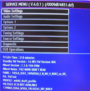
Sony Trinitron KV-SP29M53K- RM-GA002, KV-SP29M83K- RM-GA002, KV-SP29N63K- RM-GA002 – Service mode, Service adjustments, full Schematic, Disassemble procedure

Self-diagnostic function
If an error occurs, the STANDBY Indicator will automatically begin to flash.
The number of times the STANDBY Indicator flashes translates to a probable source of the problem.If an error symptom cannot be reproduced, the remote commander can be used to review the failure occurrence data stored in memory to reveal past problems and how often these problems occur.
Result for all of the following diagnostic items are displayed on screen. No error has occured if the screen displays a “0”.

HANDLING SELF DIAGNOSTIC SCREEN DISPLAY
OCP - +B overcurrent - Occurs when an overcurrent on the +B(135V) line is detected by pin 32 of IC001 (A board).  If the voltage of pin 32 of IC001 (A board) is more than 4V, the unit will automatically go to standby.
V-Protect - Occurs when an absence of the vertical deflection pulse is detected by pin 13 of IC001 (A board).
IK (AKB) - If the RGB levels* do not balance for 15 sec after the power is turned on, this error will be detected by IC001 (A board). TV will stay on, but there will be 5 times LED blinking.
Power supply NG (+5V) for video processor - Occurs when IC001 internal HV protect detects an abnormal H-Pulse (frequency) due to improper power supply to IC001. TV cuts off high voltage power of anode CRT. No picture will be detected. eg: IC602, IC604 go faulty.
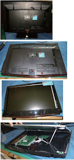
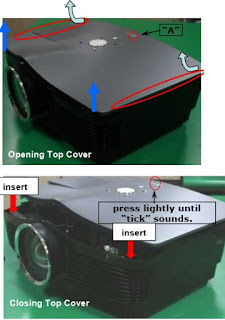
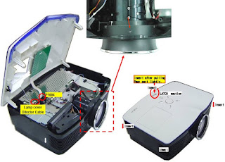
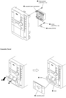
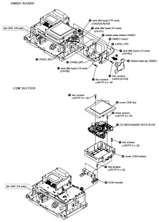
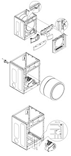
Disassembly procedure
Entering service mode and adjustments
ADJUSTMENT WITH COMMANDER
Service adjustments to this model can be performed using the supplied remote commander RM-GA002.
ENTERING SERVICE MODE
METHOD OF CANCELLATION FROM SERVICE MODE
Set the standby condition (Press [POWER] button on the commander), then press [POWER] button again, hereupon it becomes TV mode.
METHOD OF WRITE INTO MEMORY
Set to Service Mode.
2. Press 1 (UP) and 4 (DOWN), to select the adjustment item.
3. Change item by pressing 3, 6.
4. Press [MUTING] button to indicate WRITE on the screen.
5. Press - button to write into memory.
MEMORY WRITE CONFIRMATION METHOD
1. After adjustment, pull out the plug from AC outlet, and then plug into AC outlet again.
2. Turn the power switch ON and set to Service Mode.
3. Call the adjusted items again to confirm adjustments were made.
Other functions via remote control
ADJUSTMENT METHOD
Item Number 000 HPOS (Horizontal Position)
This explanation uses H POSITION as an example.
1. Select "000 HPOS" with the 1 and 4 buttons, or 2 and 5.
2. Raise/lower the data with the 3 and 6 buttons.
3. Select the optimum state. (The standard is IF for PAL reception.)
4. Write with the [MUTING] button. (The display changes to WRITE.)
5. Execute the writing with the - button. (The WRITE display will be changed to red color while executing, and back to SERVICE.)
Use the same method for all Items. Use 1 and 4 to select the adjustment item, use 3 and 6 to adjust, write with [MUTING], then execute the write with -.
In [WRITE], the data for all items are written into memory together.
2. For adjustment items that have different standard data between 50Hz or 60Hz, be sure to use the respective input signal after adjustment.
PICTURE QUALITY ADJUSTMENT (PICTURE QUALITY ADJUSTMENT)
Set TV to Video mode.
2. Set Picture mode to “CUSTOM”.
3. Input PAL 100% Color Bar to TV set (OTHER model) and NTSC 75% Color Bar (NTSC model).
4. Set the following condition:
Picture 100%, Color 0%, Brightness 50%.
5. Connect an oscilloscope to pin 4 (R output) of CN004.
6. Go to service mode and set PICT 003 “PWL” to 00h and WHBL 017 “BLBG” to 01h and PICT 002 “SOC” to 03.
7. Select SADJ 000 “PMAX” with 1 and 4 button of the commander then adjust VR with spec with 3 and 6 button until reach the spec below:
8. Then copy the adjusted PMAX data to TV mode.
9. Select Wide mode to “ON” in TV and Video mode and write “PMAX” data -6 steps (for models with V-Compression features only).
10. Press [MUTING] t - to write the data.
11. Set “PWL” and “BLBG” back to initial data.
(“PWL” : 01h “SOC” : 00 and “BLBG” : 00h).
12. Finally press [MUTING] t - to write the data.
SUB COLOR ADJUSTMENT
Set TV to Video mode.
2. Set Picture mode to “CUSTOM”.
3. Input PAL 100% Color Bar to TV.
4. Set the following condition:
Picture 100%, Color 50%, Brightness 50%, Hue 50% and Sharpness 50%
5. Set PICT 006 “WTS” to 00h.
6. Connect an oscilloscope to pin 2 (B output) of CN004 A Board.
7. Select SADJ 004 “SCOL” with 1 and 4 button of the commander then adjust with 3 and 6 so that VB2=VB3=VB4 (for PAL) then write in the data as below:
(Add 11 steps to “SCOL” (PAL) – 25"
Add 11 steps to “SCOL” (PAL) – 29"
Add 6 steps to “SCOL” (PAL) – 34")
8. Copy “SCOL” 50(PAL) video data to “SCOL” 50 (SECAM) video.
9. Then copy “SCOL” 50(PAL) video data and “SCOL” 50(SECAM) video data to “SCOL” 50(PAL) and “SCOL” 50(SECAM) TV table.
10. For NTSC model input NTSC 75% Color Bar to TV and repeat step no. 4 to 6.
11. Select SADJ 004 “SCOL” with 1 and 4 button of the commander then adjust using 3 and 6 so that VB1=VB4 then write in the data.
12. Copy “SCOL” 60(NTSC) video data to “SCOL” 60(NTSC) TV .
13. Finally copy “SCOL” 50(PAL) and “SCOL” 60(NTSC) data to “SCOL” 50(PAL) and 60(NTSC) in DVD mode.
14. Then press [MUTING] t - to write the data.
15. Set PICT 006 “WTS” back to original data.
SUB HUE ADJUSTMENT
Set TV to Video mode.
2. Input NTSC 3.58 Color Bar to TV set.
3. Set the following condition:
Picture 100%, Color 50%, Brightness 50%, Hue 50%, Sharpness 50%.
4. Connect oscilloscope to pin 2 (B output) of CN004.
5. Set to service mode and select YC 013 "TINT" with 1 and 4 button then adjust to VB1=VB2=VB3=VB4 using 3 and 6 button.
6. Press [MUTING] t - to write the data.
7. Select TV channel with NTSC 3.58 and perform step 3 to 6.
8. For single system model with NTSC 4.43, select TV channel with NTSC 4.43 and perform step 3 to 6.
9. Once adjustment is completed in Video mode, carry out adjustment in DVD mode. Input NTSC 3.58 Color Bar.
10. Connect oscilloscope to pin 2 (B output) of CN004.
11. Set to service mode and adjust service item YC 013 “TINT” with 1 and 4 button until VB1=VB2=VB3=VB4.
12. Press [MUTING] t - to write the data.
(The highest level of VB1, VB2, VB3 and VB4 should be aligned at the same line.  The ideal difference between VB2 and VB3 is within + 80mV.)
SUB BRIGHT ADJUSTMENT
1. Set TV to RF mode.
2. Input PAL monoscope to RF mode (OTHER model) and NTSC monoscope (NTSC model).
3. Set Brightness to 50% and Picture to “MINIMUM” in "CUSTOM" mode.
4. Select WHBL 010 “SBRT” with 1 and 4 button and adjust its data using 3 and 6 button so that the Cut Off level and slightly glimmer is as the specification below:
5. Write into the memory by pressing [MUTING] t -.
6. Copy the adjusted data WHBL 010 “SBRT” to Video mode.
7. Once adjustment is completed in RF and Video mode, carry out adjustment in DVD mode. Repeat step 2 to 3.Select WHBL 010 “SBRT” and adjust its data.
GEOMETRY ADJUSTMENT
H-TRAPEZOID ADJUSTMENT
1. Receive cross hatch/dot signal.
2. Adjust RV1800 on C Board to make H-Trapezoid distortion best/to obtain the center illustration shown in Table.
NORMAL MODE 50Hz / 60Hz
1. Input PAL Special Color Bar (SPCB) or PAL Monoscope (OTHER model) and Video mode or NTSC Monoscope (NTSC model) signal using a pattern generator.
2. Set Wide Mode to “OFF”.
3. Select Category items listed in Table 1.
4. Raise and Lower the data value using 3 and 6 button to obtain the center illustration.
5. Press [MUTING] t - to save the data into the memory.
6. For Korea models, copy adjusted 60Hz to 50Hz. Add 6 steps to 50Hz “HPOS” and 3 steps to 50Hz “HSIZ” and save the data.
WIDE MODE 50Hz / 60Hz (V Compression Adjustment)
1. Input PAL Special Color Bar (SPCB) (OTHER model) or Monoscope NTSC (NTSC model) signal using a pattern generator.
2. Set Wide Mode to “ON”.
3. Copy NORMAL MODE 50Hz/60Hz adjusted data for the following items:-
GEOM: 011 VSIZ, 010 VSLP, 012 SCOR and 003 VLIN
4. Select Category items listed in Table 1 except GEOM:
003 VLIN, 010 VSLP, 011 VSIZ, and 012 SCOR and
adjust the data to obtain the center illustration.
5. Press [MUTING] t - to save the data into the memory.
6. For Korea models, copy adjusted 60Hz to 50Hz. Add 6 steps to 50Hz “HPOS” and save the data.
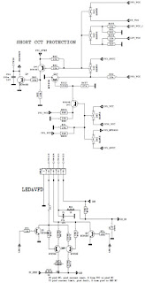
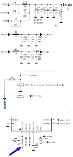
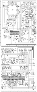
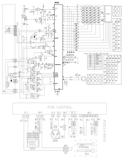
Schematic


AV RECEIVER Yamaha RX-V767/HTR-7063, RX-A800 – software update, service adjustment, initialization, Idle current adjustment

$
0
0

How to update the firmware, how to enter service mode, service mode adjustments - Yamaha AV Receiver RX V767, Yamaha RX A800
Updating firmware
When the following parts are replaced, the firmware must be updated to the latest version.
DIGITAL P.C.B.
IC951 (TI (DSP) flash ROM) of DIGITAL P.C.B
Confirmation of firmware version and checksum
Before and after updating the firmware, check the firmware version and checksum by using the self diagnostic function menu.
Start up the self-diagnostic function and select “S4.
ROM VER/SUM” menu.
Using the sub-menu, have the firmware version and checksum displayed, and note them down.
* When the firmware version is different from written one after updating, perform the updating procedure again from the beginning.
Initializing the back-up IC
(EEPROM: IC903 of the DIGITAL P.C.B.)
After updating the firmware, the back-up IC MUST be initialized by the following procedure to have proper memorization of the set up information (sound field parameters, system memory and tuner presetting, etc.).
Start up the self-diagnostic function and select “S3.
FACTORY PRESET” menu. (See “SELF-DIAGNOSTIC FUNCTION”)
Select “PRESET RSRV”, press the “MAIN ZONE ” (power) key of this unit to turn off the power once and turn on the power again. Then the back-up IC is initialized.
Required Tools
• BD, DVD or CD player (with DIGITAL OUTPUT (OPTICAL or COAXIAL) jack)
• Optical cable (when OPTICAL jack is used)
• Digital audio pin cable (when COAXIAL jack is used)
• Firmware CD
* Download the latest firmware from the specified download source and create the firmware CD.
Operation Procedures
1. While pressing the “TUNING >>” key of this unit, connect the power cable of this unit to the AC outlet.
The FIRMWARE UPDATE mode is activated and “CDDA Upgrader” is displayed.
2. Play the firmware CD on the BD/DVD/CD player. Writing of the firmware starts automatically.
3. When writing of the firmware is completed, “Update Success”, “Please...” and “Power off!!” are displayed repeatedly.
* If the display remains unchanged for more than 10 seconds after starting the firmware CD play procedure, perform the firmware CD play procedure again from the beginning.
If “FILE CORRUPTED” is displayed after “Address:XXXXXX”, make sure that the written data is not corrupted and perform Steps 1 to 3 of “Operation Procedures” again.
If “Upgrade Failed” is displayed, perform "operation procedures" again from the beginning.
4. Press the “MAIN ZONE ” (power) key of this unit to turn off the power.
5. Eject the firmware CD from the BD/DVD/CD player.
6. Start up the self-diagnostic function and check that the firmware version and checksum are the same as written ones. (See “Confirmation of firmware version and checksum”)
Self-diagnostic function
This unit has self-diagnostic functions that are intended for inspection, measurement and location of faulty point.
There are 24 main menu items, each of which has submenu items.
Starting Self-Diagnostic Function.
While pressing the “TONE CONTROL” and “INFO” keys of this unit as shown in the figure below, press the “MAIN ZONE ”(power) key of this unit to turn on the power.
The self-diagnostic function mode is activated.
Starting Self-Diagnostic Function in the protection cancel mode
If the protection function works and causes hindrance to trouble shoot, cancel the protection function as described below, and it will be possible to enter the self-diagnostic function mode.
(The protection functions other than the excess current detect function will be disabled.)
While pressing the “TONE CONTROL” and “INFO” keys press the “MAIN ZONE ” (power) key to turn on the power and keep pressing those 2 keys for 3 seconds or longer.
The self-diagnostic function mode is activated with the protection functions disabled.
In this mode, the “SLEEP” segment of the FL display of this unit flashes to indicate that the mode is self-diagnostic function mode with the protection functions disabled.
CAUTION
Using this product with the protection function disabled may cause further damage to this unit. Use special care for this point when using this mode.
Canceling Self-Diagnostic Function
Before canceling self-diagnostic function, execute setting for FACTORY PRESET of main menu No. S3. (Memory initialization inhibited or Memory initialized).
* In order to keep the user memory preserved, be sure to select PRESET INHIBIT (Memory initialization inhibited).
2. Press the “MAIN ZONE ” (power) key of this unit to turn off the power
Display provided when Self-Diagnostic Function started
The display is as described below depending on the situation the last time the power to this unit is turned off.
1. When the power is turned off by usual operation:
The FL display of this unit displays “NO PROTECT” then the main menu (sub-menu “A1-1. DSP MARGIN” of main menu No. A1 DSP AUDIO) a few seconds later.
When the protection function worked to turn off the power:
The FL display of this unit displays the data of protection function which worked at that time then the main menu (sub-menu “A1-1. DSP MARGIN” of main menu No. A1 DSP AUDIO) a few seconds later.
Note: At that time if you reactivate the self-diagnostic function after turning off the power once by pressing the “MAIN ZONE ” (power) key, “NO PROTECT” will be displayed because that situation is equal to “1. When the power is turned off by usual operation:” described above.
However the protection function history is stored in a back-up IC with a backup. For details, refer to main menu P2 PROTECTION HISTORY.”
When there is a history of protection function due to excess current.

An excessive current flowed through the power amplifier.
Supplementary information: As current of the power amplifier is detected, the abnormal channel can be identified by checking the current detect transistor.
Turning on the power without correcting the abnormality will cause the protection function to work immediately and the power supply will instantly be shut off.
Notes
• Applying the power to this unit without correcting the abnormality can be dangerous and cause additional circuit damage. To avoid this, if “I PROTECT” protection function works 1 time, the power will not turn on even when the “MAIN ZONE ” (power) key is pressed. In order to turn on the power again, start up the self-diagnostic function.
• The output transistors in each amplifier channel should be checked for damage before applying power to this unit.
• Amplifier current should be monitored by measuring DC voltage across the emitter resistors for each channel.
 When the protection function worked due to abnormal DC output.
DC output of the power amplifier is abnormal.
Supplementary information: The protection function worked due to a DC voltage appearing at the speaker terminal. A cause could be a defect in the amplifier.
Turning on the power without correcting the abnormality will cause the protection function to work in 3 seconds and the power supply will be shut off.
When the protection function worked due to abnormal voltage in the power supply section.
The voltage in the power supply section is abnormal.
Supplementary information: The protection function worked due to a defect or overload in the power supply.
Turning on the power without correcting the abnormality will cause the protection function to work in 1 seconds and the power supply will be shut off.
Notes)
• Applying the power to this unit without correcting the abnormality can be dangerous and cause additional circuit damage. To avoid this, if “PS” and “DC” protection function works 3 times consecutively, the power will not turn on even when the “MAIN ZONE ” (power) key is pressed.
In order to turn on the power again, start up the self-diagnostic function.
• The output transistors in each amplifier channel should be checked for damage before applying power to this unit.
• Amplifier current should be monitored by measuring DC voltage across the emitter resistors for each channel.
When the protection function worked due to excessive heat sink temperature.
The temperature of the heat sink is excessive.
Supplementary information: The protection function worked due to the temperature limit being exceeded.
Causes could be poor ventilation or a defect related to the thermal sensor.
Turning on the power without correcting the abnormality will cause the protection function to work in 1 seconds and the power supply will be shut off.
History of protection function
When the protection function has worked, its history is stored in memory with a backup.
Even if no abnormality is noted while servicing the unit, an abnormality which has occurred previously can be defined as long as the backup data has been stored..
Initial settings used to start Self Diagnostic Function
The following initial settings are used when starting self diagnostic function.
When self-diagnostic function is canceled, these settings are restored to those before starting self-diagnostic function.
• Master volume: -20 dB / Zone volume: +2.5dB
• Input: HDMI1 / Zone: AUDIO1
• Main menu: A1-1. DSP MARGIN
• Speaker setting: LARGE, Bass out to SWFR (All channels)
• HDMI Control: Off
• Zone: On
Details of Self-Diagnostic Function menu
DSP AUDIO
This menu is used to check audio signal route via DSP.
A1-1. DSP MARGIN
The audio signal is output including the head margin via DSP.
* When input source is stereo, signal is assigned as below.
Front L: Front L, Center, Surround L,
Surround Back L
Front R: Front R, Surround R,
Surround Back R
Front L +10 dB: Subwoofer.
DSP NON MARGIN
The SUBWOOFER signal is output including the head margin via DSP.
The audio signal other than SUBWOOFER is output without including the head margin via DSP
CONFIRMATION OF IDLING CURRENT OF AMP UNIT
Right after power is turned on, confirm that the voltage across the terminals of R1152 (SURROUND BACK Rch), R1154 (SURROUND Rch), R1150 (FRONT Rch), R1148 (CENTER), R1149 (FRONT Lch), R1153 (SURROUND Lch), R1151 (SURROUND BACK Lch) are between 0.1mV and 10.0mV.
● If it exceeds 10.0 mV, open (cut off) R1090 (SURROUND BACK Rch), R1092 (SURROUND Rch), R1088 (FRONT Rch), R1086 (CENTER), R1087 (FRONT Lch), R1091 (SURROUND Lch), R1089 (SURROUND BACK Lch) and reconfirm the voltage.
Attention
If the measured voltage exceeds 10.0mV after an amplifier repair, first check for a defective component before cutting the bias resistor.
● Confirm that the voltage is 0.2 mV to 15.0 mV after 60 minutes.

TCL L37M61AZ - L42M64AZ LCD TV Alignment Procedure - Power supply - Schematic Diagram - SMPS troubleshooting

$
0
0

How to troubleshoot the power board of TCL L37M61 and TCLL42M64 LCD TVs
Alignment Procedure – Service mode: To enter the factory mode
1.press the vol.- botton to 0 , enter the “picture” menu,cursor place the “ contrast”, input the digits 9735.
2. When using the heat key to open the factory menu , press the Freeze key if it is not the menu .
Factory menu white balance adjust and HDMI signal source inspection
It is only adjusting white balance of the HDMI signal source Adjustment in HDMI mode
1. Input HDMI signal: timing is 720P, Patter is 10 grey
2. enter the factory menu, select white balance item, press OK key , system auto covering to HDMI signal source, and so on setting the color temperature item is standard 3. adjusting the white balance machine ,setting the color coordinate to adjust the color temperature
4. press OK key to auto adjusting, until cuing is finishing
5. Looking into the fugue and screen menu , estimating screen menu or not in gear, exit the factory menu and inspecting the HDMI signal source
Accessory 1: all the displaying item signification.
X/y: about standard color temperature of the color coordinate, it is manual setting before adjusting the white balance.
Manual adjustment mode
The cursor placed to x or y,press “OK” key to enter manual adjustment of the white balance
(2).the ADC in the factory menu is been adjusted and inspecting YpbPr /VGA/AV signal source only auto adjusting the YpbPr/VGA/AV signal source ,all signal source adjustment mode as  follows:
1.YpbPr
a. switching to YpbPr signal source ,input the
720@60 contrast of 100% eight grey-scale/color –bar signal reference machine model: timing81 of bsg360a, pattern85
b. enter the ADC of the factory menu item press OK key to auto adjusting
c. after cuing auto adjustment successfully,observing displaying figure and screen menu or not in gear, exit the factory menu and inspect the YpbPr signal source.
2.VGA
a. Switching to VGA signal source , input
1024x768@60Hz 16 grey or 10 grey reference machine model: BSG360A of Timing13,pattern105
b. enter the factory menu ADC item ,press ok key to auto adjusting
c. after cuing auto adjustment successfully, observing successfully, observing displaying fugue and screen menu or not in gear, exit the factory menu and inspect the VGA signal source
3.AV
d. Switching to AV signal source , input PAL
100% saturation of the 8 grey signal source reference machine model: BSG360A of Timing,pattern 85
e. enter the factory menu ADC item ,press OK key to auto adjusting
f. after cuing auto adjustment successfully, observing successfully, observing displaying figure and screen menu or not in gear, exit the factory menu and inspect the AV signal source.
4 Inspect ATV/DTV signal source parting switch to ATV or DTV ,and then scanning,observing or not losing channel and the picture displaying and volume in gear or not
5 
the factory menu function setting.
1) according to so you saying item: enactment LCD panel factory appellation, factory menu heat key setting to OFF, hotel mode setting to off; Electrify mode setting to STB
2) select factory init item, press OK key to initialization operating about boot-strap
WARNING: during finishing the Factory init operating to packing , if the TV has been boot-strapped , the TV must operate again before packing.
SMPS schematic: Standby circuit working
When switching on ,at first the standby circuit work. Supply 5V to the figure board , the main power start working when receiving the figure board boot-strap signal. Output: 24v12v300v volts d.c. pass the D810R832and then transformer(T803) primary coil there into 3 pin connect pin 567 of U4 VDDfrom U4 sourcedrain put throughand so that the transformer(T803) primary coil put through  telepathy secondary 9 pin outputting through D807 commute 5V
Standby voltageR838 sampling 5v voltageconnect sampling 5Vconnect to pin 1 TLHPC92 therepathy U3 pin 34 put through  leave each other Connect from the signal to U4 PIN 34control U4 outputting  and so that the transformer output the steady 5v
At the same timethe transformer T803 primary coil 4 pin divide into two-way outputting
1one-way output 15v to the VCCsupply to IC supplying power
2
one-way output to U4 supply power.
Switch on work flow
It passes R842R841D819 when receiving the figure board outputting the switch on high level signal  and then send to Q808 BaseQ808 break over  TLU2 -1 2 pin break overthe signal coupling to TL U2 pin 34.  At the same time Q807 cut offTLU2 pin 1 - 2 disconnectionnot coupling the signal to TLU2 pin 3 4. At the same time Q807 cut off15V cannot supply through the Q807 outputting the VCCU5 and U6 stop working if they cannot receive the supply power.
PFC circuit
15V ingress and U6 startup,P7 OUTPUT CONTROLLING Q801 CUT OFF AND BREAK OVER L801 is energy storage constantly commute the voltage Upgrade the 380V or not , pass the C807 filter, outputting to PWM circuit.
PWM circuit
After 15v enter u5 pin P6, U5 start working, p5 output the pulse signal control Q805 and Q802 basewhen the pulse signal is high level,Q805 cut offQ803 break overVCC pass though the Q802 and R813 to charge up C820. when the pulse signal is low level,Q805 break overQ803 cut offC802 pass though Q820 discharge . on account of C820 overlap cycle charge and dischargeon account of T802 secondary coil coupling to signal variety,and so that control Q803 AND Q806 cut off and disconnect. In this way PFC Circuit output voltage connecting the transform T801 primary coilalso repeat constantly deposited entry and released energy exchange course , and then telepathy to secondary coil and output voltage: 12v24v 12V and 24V steady circuit. Pass through R811 sampling 24v and R808 sampling 12v,sampling the signal passing through U1 telepathy controlling U5 PIN P2 ,adjust U5 PIN P5 Output the pulse width adjust T801 output.
Overvoltage protect: When the voltage is over and sampling signal mix through D809R856 , the high level send to Q812 baseat the same time Q810 collector is high level.
Q810 is break overthrough D820 connect to R842the potential alter low level  the switch on signal high level can not operateTV starts standby.
Low-voltage protect: When it is in gear about 24v , 24v through R1004R1005R1006 change the voltagethe Q1001 break-overQ1001 collector is lower level.
When the voltage is lower 24v, D1002 cannot break –overQ1001 collector is high level ,D1001 and Q812 break-over switch-on signal voltage change lower, TV shift standby.
SMPS schematic
SMPS troubleshooting procedure
SMPS faults: No voltage
Analysis and detect: at first testing the switching on
 p802 gain 2.2v switching on voltage in power board, constant the power is ontesting 12v and 24v is 0vmeasuring 5v is in gear. Showing the TV can standby in gear. If measuring 12v and 24v is 0Vthe problem cause is 12v and 24v commonality part.
12v and 24v commonality part is PFC part and power PWN part  over current and voltage protect part. At first measure L809 PFC voltage.  If it discovering 380v is 0Vthe problem is PFCcontact the PWM problem , primary analyzing cause is 15V circuitU5 and U6 can not work when only 15V has not in gear.
We know: the transformer T803 secondary coil 4 pin output second part:
1. one way output 15V to VCC
supply to ic power supply
2. one way to U4 supply power
supply to 5VSTB
because 5V is in gearIC power supply is 15Vmeasure R826 VCC outputting voltage is 0V. measure R826 resistance to GND is in gear. And then measuring Q807 transmit is not voltage. Measure D824discovering one pin has voltage measure D824 discover the D824 disconnectionreplace the D824the voltage is ok.
No voltage
Analysis and detect: at first testing the switching on
p802 gain 2.2v switching on voltage in power board, constant the power is ontesting 12v and 24v is 0vmeasuring 5v is in gear. Showing the TV can standby in gear. Measuring 12v and 24v is 0V, the problem cause is 12v and 24v commonality part.
12v and 24v commonality part isPFC part and power PWN part  over current and voltage protect part. At first is there 15V of VCC Is there Q807 Transistor of 13V.  U2 has not gain the switch on controlling signal.  Disconnect D820and than measure  now avoid the problem of over current and voltage  the problem is the switch on signal has not effect. Constant switch on signal has inputted the P802testing discover R842 disconnectionthe Switch on signal has not send to the Q808replace R842The TV switch on testingthe fault avoid.
No voltage
Analysis and detect: at first testing the switching on
p802 gain 2.2v switching on voltage in power board, constant the power is ontesting 12v and 24v is 0vmeasuring 5v is in gear.  Showing the TV can standby in gear. If measuring 12v and 24v is 0Vthe problem cause is 12v and 24v commonality part.
12v and 24v commonality part isPFC part and power PWN part  over current and voltage protect part.
At first disconnect D820  affirm where the problem is part  and then measure 13V of VCC if it is in gearcontinue testing PFC voltage is in gear
So that determinant the problem is protect circuitmeasuring D820 cathode to GND resistancediscovery resistance is littler than in gear  testing Protect circuitdiscovery Q812 short circuit attain. Replacing the Q812 ,the TV is ok.
Switch on voltage moment12V testing point is 20V24V testing point is 30V. fall to 0.4V or not moment .
Analysis and detect: at first testing the switching on
p802 gain 2.2v switching on voltage in power board, constant the power is onswitch on voltage moment12V testing point is 20V,24V testing point is 30V.fall to 0.4V or not moment .measuring 5V is in gearthe TV can standby in gearthe problem is 12V and 24V steadfast voltage pass from R811 sampling 24V and R808 sampling 12Vsampling signal pass though telepathy controlling U5 pin P5, and then output the pulse widthadjust T801 outputting.
Detecting 12V and 24V steadfast voltage partdiscovering Q804 is bad, replace it the fault rectified.
When5V, dithering, and the output is 4V, no voltage at 12 V and 24V
Analysis, examine and repair: Open the panel and test, find out when 5V, dithering, the output is 4V, and no output at other voltage, it means there is something wrong with standby, it can’t export the stable 5V standby voltage.
At first, Check whether the commute bridge exports voltage: measure and find out there is 300 V direct current in D810, then check U4 to find out whether it starts work, measure the start voltage of U4 at first. There is dithering in 11V, but 13V is normal, the matter is in support part of work voltage, measure pin 4 voltage output of D803,there has voltage, measure D822, it is no voltage, then measure R847, find out there is plough, exchange it and eliminates the malfunction.
No voltage at 5V, 12 V and 24V.
Analysis, examine and repair: open the panel and test, there is no voltage, means the machine has something wrong with standby, it can’t output the 5V standby voltage, so it can’t produce 12V and 24V.
Check whether the commute bridge exports voltage: measure and find out there is 300V direct current in D810,then check U4 to find out whether it starts work,
measure the start voltage of U4 at first. There is dithering in 6-7V, but 13V is normal, measure 4 feet voltage output of D803, there has voltage, measure D822, it is
7V, find out no output when test D824,shows that it can’t run normally when at 5V , so exchange the U4, malfunction disappears.
No voltage for 12V and 14V.
Analysis, examine and repair: open the machine and test at first, find out when standby at 5V voltage is normal means no problem with standby, provide the 2.2V start voltage, no voltage output, so there is something wrong with the 12V and 14V voltage part, maybe the problem appears in PFC, PWM and protective circuit.
Measure the output voltage of VCC, 12V in R836, at this time there is noise in transformer, it is the voltage output reducing, maybe there is something wrong with the protective circuit, then cut D820 of protective circuit, test again, there is normal voltage output, so it can conclude that the problem is in protective circuit, the problem is over current and voltage or low-voltage
low-current protect circuitCut the protect point after connect the D820, voltage goes back to normal when cuts the D1001, then test the low-voltage protect circuit , Q1001 is plough, exchange it and the malfunction disappears.
The TV has no power
Analysis, examine and repair: check the machine first, find out the fuse is cut and no obvious component burned-out mark, circuitry has over current or voltage circuit since the fuse is burned, means there is short circuit in somewhere. Measure and find out the Q801 has been short circuit, no short circuit finding in other parts, exchange the Q801, test against, 5V voltage is normal, but no output at 12V -24V, because the PFC is broken, the voltage output of PFC is only about 320V, PFC doesn’t run, the power supply voltage of PFC at 14V, it is normal, so decide to exchange U6, the malfunction is still here, measure each feet against floor resistance of U6 in turn, find out the R869 is plough, exchange and test, eliminates malfunction, the fact is that R869 disconnect caused the U6 over current protect circuit runsU6 stop the output, so there is no voltage output of PFC, and no voltage.
No voltage for 12V and 14V.
Analysis, examine and repair: open the panel and test at first, find out when standby at 5 V, the voltage is normal, means no problem with standby, then provide 2.2 V start voltage, make out no output at12V and 14V. The TV is standby.
Problem both at 12V and 14V voltage, maybe there is some matter with PFC, PWM and protective circuit, so measure output of PFC first, it is 320V, means PFC doesn’t work, cut down the protective circuit, start the machine to test the output on 12V and 14V voltage, it is normal, so the problem appears in protective circuit, cut down the over current protect point separately to test , malfunction still, then cut down the exceed press protect, malfunction still,too, cut down the low-voltage protect Q1001 at last, malfunction disappears, and none of
base voltage with Q1001, test and find out that 24V low-voltage protect sampling resistance R1004 disconnection. Open the machine after exchange it, malfunction disappears.
No voltage for 12V and 14V.
Analysis, examine and repair: open the panel and test at first, find out when standby at 5 V, the voltage is normal, means no problem with standby, then provide 2.2 V start voltage, make out no output at 12V and 14V. The machine is standby, problem appears both at 12V and 14V voltage, maybe there is some matter with PFC, PWM and protective circuit, so measure output of PFC first, if is 380 V, means PFC runs normally. It can conclude that problem is at 12V and 14V voltage part.
Since no voltage for both at 12V and 14V, the chance that feedback loop gets in trouble is not big, check the PWM circuit first, examine the going of U5, check whether there is drive voltage of pin P5 on U5,dittering on 1.5V more or less is normal. Then measure against floor resistance of P5 on U5, cut down the outing circuit, short circuit, it can conclude that U5 has been broken, open after exchange it, find out that the malfunction disappears.

Sharp CTV - 25N-M100/180, 25N-S100/180, CN25M10, CN25S18, CN25S20 – SN91 Chassis – how to enter the service mode, adjustment procedure in detail, default data values

$
0
0

Sharp 25NM100, Sharp 25NS100 - service mode adjustments, schematic (full)
When performing any adjustments to resistor controls and transformers use non-metallic screwdrivers or TV alignment tools.   Before performing adjustments, the TV set must be on at least 15 minutes.
Circuit protection
The receiver is protected by a 4.0A fuse (F701), mounted on PWB-A, wired into one side of the AC line input.
After service has been performed on the horizontal deflection system, high voltage system, B+ system, test the X-Radiation protection circuit to ascertain proper operation as follows:
Apply 120V AC using a variac transformer for accurate input voltage.
2. Allow for warm up and adjust all customer controls for normal picture and sound.
3. Receive a good local channel.
4. Connect a digital voltmeter to TP653 and make sure that the voltmeter reads 11.2 ±0.6V.
5. Apply external 13.8V DC at TP653 by using an external DC supply, TV must shut off.
6. To reset the protector, unplug the AC cord and make a short circuit between TP651 and TP652. Now make sure that normal picture appears on the screen.
7. If the operation of the horizontal oscillator does not stop in step 5, the circuit must be repaired before the set is returned to the customer.
High voltage is not adjustable but must be checked to verify that the receiver is operating within safe and efficient design limitations as specified checks should be as follows:
Connect an accurate high voltage meter between ground and anode of picture tube.
2. Operate receiver for at least 15 minutes at 120V AC line voltage, with a strong air signal or a properly tuned in test signal.
3. Enter the service mode and select the service adjustment "S19" and Bus data "01" (Y-mute on).
4. The voltage should be approximately, 28.7kV (at zero beam).
If a correct reading cannot be obtained, check circuitry for malfunctioning components. After the voltage test, make Y-mute off to the normal mode.
For adjustments of this model, the bus data is converted to various analog signals by the D/A converter circuit.
[There are still a few analog adjustments in this series such as focus and master screen voltage.  Follow the steps below whenever the service adjustment is required. See "Table-B" to determine, if service adjustments are required.]
Service mode
Before putting unit into the service mode, check that customer adjustments are in the normal mode. Use the reset function in the video adjustment menu to ensure customer controls are in their proper (reset) position.
To enter the service mode and exit service mode.
While pressing the Vol-up and Ch-up buttons at the sametime, plug the AC cord into a wall socket.
Now the TV set is switched on and enters the service mode.
To exit the service mode, turn the television off by pressing the power button.
Service number selection
Once in the service mode, press the Ch-up or Chdown button on the remote controller or at the set.
The service adjustment number will vary in increments of one, from "S01" to "OP2" (25N-M100/ 180, CN25M10), "S01" to "M05"(25N-S100/180, CN25S18/20).
Select the item you wish to adjust.
Data number selection
Press the Vol-up or down button to adjust the data number.
Default data values
VCO Adjustment
1. Connect a digital voltmeter between pin (44) of IC201 and ground.
2. Receive a good local channel.
3. Enter the service mode and select the service adjustment "S10".
4. Adjust the data so that digital voltmeter reads 2.2V.
5. Adjustment is completed, remove the voltmeter, return to "normal" mode.
RF AGC Adjustment
1. Receive a good local channel.
2. Enter the service mode and select the service adjustment "S08".
3. Set the data value to point where no noise or beat appears.
4. Select another channel to confirm that no noise or beat appears.   You will have to come out of the service mode to select another channel.  Setting the data to "00" will produce a black raster.
Screen Adjustment
1. Connect a oscilloscope between TP854 and GND on the CRT Unit.
2. Receive a good local channel.
3. Enter the service mode and select the service adjustment "S03" and set the data value to "00" to set the color level to minimum. (Record original data code under adjustment "S03" before changing) You may skip this step, if you selected a B/W picture or monoscope pattern.
4. Select the service adjustment "S19" and adjust the data value to "01", this turn off the luminance signal (Y-mute).
5. Select the service adjustment "S04" and adjust data value to obtain 2.35 volts on the oscilloscope screen.
6. Adjust the master screen control until the raster darkens to the point where raster is barely seen.
7. Adjust the service adjustments "S11" red, "S12" green and "S13" blue to obtain a good grey scale with normal whites at low brightness level.
8. Select the service adjustment "S19" and reset data to "00". Select the service adjustment "S03" and reset data to obtain normal color level.
9. Remove oscilloscope, and reset the master screen control to obtain normal brightness range.
White Balance Adjustment
1. Receive a good local channel.
2. Enter the service mode and select the service adjustment "S03" and set to "00" (minimum color)(Record original data code under adjustment "S03" before changing). "S03" does not have to be adjusted, if you selected a B/W picture or monoscope pattern.
3. Alternately adjust service adjustment data of "S14" and "S15" until a good grey scale with normal whites is obtained.
4. Select the service adjustment "S03" and adjust data to obtain normal color level.
Sub-Picture Adjustment
1. Receive a good local channel.
2. Make sure the customer picture control is set to maximum.
3. Enter the service mode and select the service adjustment "S01".
4. Adjust the data value to achieve normal contrast range.
Sub-Tint Adjustment
1. Receive a good local channel.
2. Set customer tint control to center of it's range.
3. Enter the service mode and select the service adjustment "S02".
4. Adjust "S02" data value to obtain normal flesh tones.
Vertical-Size Adjustments
1. Receive a good local channel.
2. Enter the service mode and select the service adjustment "S09".
3. While observing the top and bottom of the screen, adjust "S09" data value to proper vertical size.
Vertical Phase Adjustment
1. Enter the service mode and select the service adjustment "S06".
2. Adjust data value to "00".
Note: This must be set "00" when changed data retrace line will appear.
Horizontal Position Adjustment
1. Receive a good local channel.
2. Enter the service mode and select the service adjustment "S07".
3. Adjust "S07" data value so that picture is centered.
Caption Position Adjustment (Horizontal)
1. Receive a good local channel.
2. Enter the service mode and select the service adjustment "S18".
3. A black text box appears on the screen
4. Adjust "S18" data value so that text box is positioned in the center of the screen.
3.58MHz Trap Adjustment- NTSC
1. Receive a good local channel.
2. Enter the service mode and select the service adjustment "S16".
3. This is a two position adjustment, "00" is ON, "01" is OFF.
4. Models should be adjusted as follows.
Sharpness and Audio Balance Adjustments
1. Receive a good local channel.
2. Enter the service mode and select the service adjustments "S05" for sharpness and "S17" for balance.
» Sharpness adjustment
3. Adjust data value to "28"(center of data range) for sharpness adjustment.
» Audio balance adjustment
4. Adjust data value to "20"(center of data range) for Audio balance adjustment.
Energy save offset Adjustment
1. Enter the service mode and select the service adjustment "S20".
2. Adjust data value to "23".
Note : This position is used to preset the level for the energy save function.
Other Adjustments
1. Enter the service mode.
2. Adjust the following data values as listed below.
MTS ADJUSTMENT - (Only for 25N-S100/180, CN25S18/20)
MTS Level Adjustment
1. Feed the following monaural signal to pin (14) of IC3001.  Monaural signal : 300Hz, 245mVrms
2. Connect the rms voltmeter to pin (39) of IC3001.
3. Enter the service mode and select the service adjustment "M01".
4. Adjust the data so that the rms voltmeter reads. 490 ±10mVrms.
MTS VCO Adjustment
1. Keep the unit in no-signal state.
2. Connect the frequency counter to pin (39) of IC3001.
3. Connect a capacitor (100µF, 50V) in between positive(+) side of C3005 and ground.
4. Enter the service mode and select the service adjustment "M02"
5. Adjust the data so that the frequency counter reads. 62.94 ±0.75kHz.
Filter Adjustment
1. Feed the following stereo pilot signal to pin (14) of IC3001 .
Stereo pilot signal: 9.4kHz, 600mVrms.
2. Enter the service mode and select the service adjustment "M03".
3. Adjust the data at the point where "OK" appears on the screen. The "OK" represents the approximate center of the adjustable range of the data.
Separation Adjustment
1. Connect the rms voltmeter to pin (39) of IC3001.
2. Receive the following composite stereo signal 1.
Composite stereo signal: 30% modulation, left channel only, noise reduction on, 300Hz
3. Enter the service mode and select the service adjustment "M04".
4. Adjust the data until the AC voltage reading of the rms voltmeter is minimum.
5. Receive the following composite stereo signal 2.
Stereo signal: 30% modulation, left channel only, noise reduction on, 3kHz
6. Enter the service mode and select the service adjustment "M05".
7. Adjust the data until the AC voltage reading of the rms voltmeter is minimum.
8. Take the above steps 1 thru 8 again for fine adjustment.
Schematic

Vestel Power board IPS55 problems – Troubleshooting

$
0
0
17IPS55 board includes AC/DC a full bridge diode rectifier, a DC/DC low power
Flyback converter for stand-by voltage +5V and half-bridge resonant converter for +24V & +12V and two DC/DC Boost Converter stages having 24V input voltages. Total maximum
input power is 250W at 100Vac input voltage.

Power board has low power consumption for stand-by mode. The only voltage is supplied at stand-by condition is 5V.
For low power consumption in standby mode, +24V and +12V outputs is not activated. The only voltage in standby mode is 5V and allowed maximum current is 20mA in this condition.
CN8-INPUT.
Connectors and voltages
Problems and checks - DS is not working
DS is working but there is no backlight, DS is working but there is no sound.

LG Mini Hi-Fi system OM5540 330W – how to update the firmware, repair hints, schematic

$
0
0

How to update the firmware of LG OM5540 Mini hi-fi system, SMPS and main amplifier schematic, troubleshooting, ICs and connector voltages
Hidden key mode
Disc Lock On/Off (CD Function Only Active)
Front Key : STOPRCU Key : STOP
 Check Version and Option code
Front Key : STOPRCU Key : PLAY/PAUSEYou can change [Audio MCU Version <-> CD Controller Version <-> EEPROM Option] by SKIP+/-.
Clear EEPROM
Front Key : STOPRCU Key : SKIP-
Edit EEPROM
 Front Key : STOP
RCU Key : SKIP+ You can change the digit of option by SKIP+/-.You can edit 0~f by REPEAT or PLAY/PAUSE key.
Bluetooth DUT
Front Key : STOPRCU Key : PROGRAMBluetooth model only
Power Disc Lock On/Off (CD Function Only Active)
Front Key : STOPRCU Key : EQ
Amp Clip On/Off
 Front Key : STOPRCU Key : Mute
Amp Clip Mode Change (Amp Clip On > Amp Clip Off > Level Down display).
Service information forEEPROM


PROGRAM DOWNLOAD & UPDATE
MICOM PROGRAM
Download program file name must be MICOM_OM5540_YYMMDDX.HEX
If security program (Water Wall) is activated on your PC, you must save the file to the USB storage device and disable the security software, then download the file to your set. Downloading file proceeds in the same way at USB1 function and USB2 function.
Caution: When downloading the file, you should neither unplug the USB device, change to the other function, nor power off the device. USB device must be unplugged when the downloading process is completed.
MCS PROGRAM
Download program file name must be HG440_OM5540_YYMMDDX.bin
If security program (Water Wall) is activated on your PC, you must save the file to the USB storage device and disable the security software, then download the file to your set. Downloading file proceeds in the same way at USB1 function and USB2 function.
Caution: When downloading the file, you should neither unplug the USB device, change to the other function, nor power off the device. USB device must be unplugged when the downloading process is completed.
EQ PROGRAM
Download program file name must be EQ_PRG.BIN
If security program (Water Wall) is activated on your PC, you must save the file to the USB storage device and disable the security software, then download the file to your set. Downloading file proceeds in the same way at USB1 function and USB2 function.
Caution: When downloading the file, you should neither unplug the USB device, change to the other function, nor power off the device. USB device must be unplugged when the downloading process is completed.
Troubleshooting

NO POWER
If the unit doesn’t work by no power problem, repair the set according to the following
(1) FUSE & BRIDGE DIODE
Please check and replace F901, BD901, TH901 or TH903 on SMPS board.
1) Check if the fuse F901 is open or short-circuit.
2) Check if the bridge diode BD901 is short-circuit by over current with a digital multi meter.
3) Check if the NTC thermistor TH901 or TH903 is normal or open.
(2) D951
Please check and replace D951 on SMPS board.
1) Check the anode-cathod voltage of D951 with a digital multi-meter, it is normally 0.2 ~ 0.3 V.
 If it doesn’t have any voltage, it’s destroyed. Replace it with a new one.
NO BOOTING WHEN POWER ON THE SET
The set doesn’t work when press the power button on the front board or the remote control.
(1) FLASH MEMORY
Please check and replace IC503 on MAIN board.
1) Check 5.6 V to CN501 in standby mode.
 If there is no 5.6 V, check the SMPS.
2) Check 12 V, F+, F- and PVDD when power on the set.
- If the set doesn’t work regardless of what the KEY1 changes high to low while pressing the power button.
X500 and X501 work normally but, if you can not power on the set, replace IC501 with a new one on the MAIN board.
VFD IS NOT DISPLAYED WHEN POWER ON THE SET
When power on the set, any icons or characters on VFD are not displayed.
Please check and replace DIG400 on FRONT board.
1) Check if VKK, FL+ and FL- are output from SMPS to VFD via the MAIN board.
2) Check if IC501 outputs VFD_D0, VFD_CLK and VFD_STB to the FRONT board.
3) Check the GR signal(pulse signal) of IC301 on the FRONT board.
Check the SG signal(pulse signal) of IC301 on the FRONT board.
 If the GR and SG signal isn’t output, replace IC301 with a new one.
 If the GR and SG signal is output, replace DIG302 with a new one.
NO SOUND
There is no sound output by DIGITAL AUDIO AMP DAMAGE
(1) BY DIGITAL AUDIO AMP DAMAGE (IN ALL FUNCTIONS)
Please check and replace IC700 on MAIN board.
1) Check PWM_FL± signals from IC601 to IC700 each input function.
 If no signal, check if I2S audio signals are entered to IC601.
2) Check the following I2S signal flow. < I2S audio signal Interface >
- MCS_BCK: IC501_Pin E1 --> IC601_Pin23
- MCS_LRCK : IC501_Pin D1 --> IC601_Pin22 (44.1 kHz)
- MCS_DATA_OUT : IC501_Pin E2 --> IC601_Pin24
- MCS_MCLK : IC501_Pin D2 --> IC201_Pin44
If there is any trouble, check the power for each IC. The power is normal but, if the signal waveform to the IC is distorted or no signal, replace it with a new one.
3) Check PVDD.
 If PVDD is abnormal, check the SMPS.
4) Check +12 V for driving the gate of AMP IC.
a. All the powers are normal, but if +12 V is low, there is possible for AMP IC to be damaged.
b. Remove L702, L706 one by one.
When removed a inductance, if +12 V is recovered, the IC connected to it was damaged.
c. Replace the IC with a new one.
5) Check the impedance between IC700_OUT_A/OUT_D & GND.
a. If the impedance is 0 Ω, the IC must be damaged.
b. After removing the heat sink, replace it with a new one.
There is no sound output in the USB FUNCTION
 (2) IN THE USB FUNCTION
Please check and replace IC501 on MAIN board & IC460 on USB board.
1) Check +5 V_USB to USB board.
If the USB LED are turned on, the voltage is okay, if so not, check +5.6 V to pin3 of CN460.
2) Check USB D1± or USB D2± from MAIN board to USB board.
a. Check 2.0_D1± signals(pin U7, U8) or 1.1_D1± signals(pin A7, A8) to IC501on MAIN board.
b. Check USB± signals to CN421 (pin 2, 3, 5, 6).
If there is any trouble, check the power for each IC. The power is normal but , if the signal waveform to the IC is distorted or no signal, replace it with a new one.
3) Check if “Digital audio AMP block” on item 4-(1) is normal.
There is no sound output in the AUX FUNCTION
(3) IN THE AUX FUNCTION
Please check and replace IC201 on MAIN board.
1) Check AUX_L/R signals to IC201 (Pin23, 24).
2) Check if MCS_BCK, MCS_LRCK & MCS_MCLK are entered from IC501 to IC201.
3) Check if ADC_DATA is entered from IC201 to IC501.
Ö If no signal, check +5 V & +3.3 V(ADC) for IC201. If is NG, replace it a new one.
4) Check the following I2S signal flow from IC501 to IC601. (Refer to item 4-(1).)
If there is any trouble, check the power for each IC. The power is normal but, if the signal waveform to
the IC is distorted or no signal, replace it with a new one.
5) Check if the digital audio AMP block is okay. Refer to “Digital Audio AMP” guide on Item 4-(1).
 If AMP is damaged, replace it with a new one.
There is no sound output in the TUNER FUNCTION
 (4) IN THE TUNER FUNCTION
Please check and replace IC201, TU500 on MAIN board.
1) Check if TUNER_LR is entered from Pin1, 3 of TU500 to IC201(Pin26, 27).
 If no signals, check +3.3 V for tuner power.
 Check if the tuner control signals (CLK, DAT, CE, RST, SLT) are entered from IC501 to TU500.
If it doesn’t work, replace TUNER with a new one.
2) Check if MCS_BCK, MCS_LRCK, & MCS_MCLK are entered from IC501 to IC201.
3) Check if ADC_DATA is entered from IC201 to IC501.
 If no signal, check +5 V & +3.3 V(ADC) for IC201. If is NG, replace it with a new one.
4) Check the following I2S audio signal flow from IC501 to IC601. (Refer to item 4-(1).)
 If there is any trouble, check the power for each IC. The power is normal but, if the signal waveform to the IC is distorted or no signal, replace it with a new one.
5) Check if the digital audio AMP block is okay. Refer to “Digital Audio AMP” guide on item 4-(1).
 If AMP is damaged, replace it with a new one.
There is no sound output in the PORTABLE FUNCTION
 (5) IN THE PORTABLE FUNCTION
Please check and replace IC201 on MAIN board.
1) Check PT_L/R signals to IC201 (Pin9, 10).
2) Check if MCS_BCK, MCS_LRCK, & MCS_MCLK are entered from IC501 to IC201.
3) Check if ADC_DATA is entered from IC201 to IC501.
 If no signal, check +5 V & +3.3 V(ADC) for IC201. If NG, replace it a new one.
4) Check the following I2S signal flow from IC501 to IC601. (Refer to item 4-(1).)
 If there is any trouble, check the power for each IC. The power is normal but, if the signal waveform to the IC is distorted or no signal, replace it with a new one.
5) Check if the digital audio AMP block is okay. Refer to “Digital Audio AMP” guide on Item 4-(1).
 If AMP is damaged, replace it with a new one.
There is no sound output in the MIC FUNCTION
Please check and replace IC203 on MAIN board and IC420 on front MIC board.
[ How to troubleshoot (Countermeasure) ]
1) Check MIC_SIG signal, from JACK421, JACK422 to IC420 (Pin3) on front MIC board.
2) Check MIC_SIG signal from IC420 (Pin4) to CN423.
 If no signal, check +5 V for IC420. If NG, replace it a new one.
3) Check MIC_SIG signal from CN423 (Pin4) to CN420.
4) Check if MCS_BCK, MCS_LRCK, & MCS_MCLK are entered from IC501 to IC203.
5) Check if ADC_DATA is entered from IC203 to IC501.
 If no signal, check +5 V & +3.3 V(ADC) for IC203. If NG, replace it a new one.
6) Check the following I2S signal flow from IC501 to IC601.(Refer to item 4-(1).)
 If there is any trouble, check the power for each IC. The power is normal but, if the signal waveform to the IC is distorted or no signal, replace it with a new one.
7) Check if the digital audio AMP block is okay. Refer to “Digital Audio AMP” guide on item 4-(1).
 If AMP is damaged, replace it with a new one.
SMPS schematic
Main amp schematic


Main DSP schematic
IC voltages and connectors

How to upgrade the software – how to enter the service mode- Daewoo DLA37 LCD TV

$
0
0

Applicable to Daewoo DLA-32C7LAB, DLA-32C7LABD,DLA-37C7LAB,DLA-37C7LABD,DLA-42C7LAB,DLA-42C7LABD
Color Standard : NTCS, ATSC
Reception Channel : Ch 2~13 (VHF), Ch 14~69 (UHF), Ch 1, 14~125(Cable)
Sound Transmission System : FM Mono, 2 Carrier, Dolby Digital
V Chip(Parental Control) SPEC
i) The rating doesn't work in PIP/POP mode. Reserves case is the same.
ii) The rating setting is possible only on the menu.
iii) Initial password : 2-2-1-1.
iv) Universal key cord (When user does not know password) : 5-4-2-2.
To enter SERVICE MODE,
A. Press “<VOL”-> “MUTE”-> “DISPLAY”-> “MUTE” button of remote controller (R-55M15)
B. Press “S9” button of SERVICE REMOTE CONTROLLER.
BACK-LIGHT INVERTER CHECK
Pin 14 is Status Output of Back-light Inverter.
3.0V to 5.0V > Normal
0V to 0.7V > Abnormal
Software Upgrade procedure
To upgrade PIC, remove(open) jumper of JP601. After upgrade completed, JP601 must be shorted with Jumper to normally operate the video board.
Run PICkit 2 Microcontroller Programmer
confirm if pickit 2 microcontroller programmer deteced device(PIC16F690) appropriately or not.
Importing HEX file for upgrade
Write Click.
remove Pickit2 upgrade board when complet massage is come out.
Short JP601 with Jumper to normally operate the video board.
Flash Upgrade
Installing CDM Driver.
• Download the latest available CDM drivers from the FTDI web site and unzip them to a location.
• Connect the device to a spare USB port on your PC.
Once the composite driver has been installed Windows Found New Hardware Wizard will launch.
The screen below is shown. Select “No, not this time” from the options available and then click “Next” to proceed with the installation.
Select “Install from a list or specific location (Advanced)” as shown below and then click “Next”.
Select “Search for the best driver in these locations” and enter the file path in the combo-box (ex.“E:£‹CDM 2.00.00”in the example below) or browse to it by clicking the browse button.
Once the file path has been entered in the box, click next to proceed.
The following screen will be displayed as Windows XP copies the required driver files.
Windows should then display a message indicating that the installation was successful.
Click Finish to complete the installation for the first port of the device.
The Found New Hardware Wizard will launch automatically to install the COM port emulation drivers.
As above, select “No, not this time” from the options and click “Next” to proceed with the installation.
Select “Install from a list or specific location (Advanced)” as shown below and then click “Next”.
Select “Search for the best driver in these locations” and enter the file path in the combo-box (ex.“E:£‹CDM 2.00.00”in the example below) or browse to it by clicking the browse button.
Once the file path has been entered in the box, click next to proceed.
Screen will be displayed as Windows XP copies the required driver files.
Windows should then display a message indicating that the installation was successful.
Click Finish to complete the installation for the first port of the device.
Open the Device Manager (located in “Control Panel£‹System” then select the “Hardware” tab and click “Device Manger”) and select “View > Devices by Connection”, the device appears as a USB Serial Converter with an additional COM port with the label “USB Serial Port”.
Connect USB cable to the USB port of the computer.
• Connect the phone jack cable the service port of set.
• Run Flashupgrader.exe in the PC to excute the program.
Select current Upgrade file
i) Click “Choose...”button to select the file you want to upgrade.
ii) Select the file (pwSDK.inf) that you want to upgrade.
Select correct COM Port and Baud Rate(115200) as shown below.
Then press Flash button to finish setup.
Turn on the power and then upgrade program will start the download.
When the upgrading is complete, a window (below) will be opened.
Press “Finish” button to complete the process.


JVC XV-S40BK - XV-S42SL - XV-S45GD - XV-S30BK SERVICE MODE AND MECHANICAL DISASSEMBLING

$
0
0

JVC  XV-S40BK - XV-S42SL - XV-S45GD  - XV-S30BKservice  mode and mechanical disassembling 
Disassembling
Loading assembly section
Removing the clamper assembly
Remove the four screws A attaching the clamper assembly.
Move the clamper in the direction of the arrow to release the two joints A on both sides.)
Removing the tray
Prior to performing the following procedure, remove the clamper assembly.
Push b of the slide cam into the slot on the left side of the loading base until it stops.
Draw out the tray toward the front.
Removing the traverse mechanism assembly
Prior to performing the following procedure, remove the clamper assembly and the tray.
Remove the four screws B attaching the traverse mechanism assembly.
Removing the elevator
Prior to performing the following procedure, remove the clamper assembly, the tray and the traverse mechanism assembly.
Extend each bar e inside of the loading base outward and detach the elevator shaft.
Removing the motor assembly
Prior to performing the following procedure, remove the clamper assembly, the tray, the traverse mechanism assembly and the elevator.
Remove the belt from the pulley.
Remove the screw C attaching the motor assembly.
Turn over the body and remove the screw D attaching the motor assembly.
Release the two tabs g retaining the motor board.
Adjustment method
(1) Initialization method
(2) Display of "Laser current value" and "Jitter value"
If microprocessor (IC401,IC402,IC403) or pick-up is replaces, initialize the
DVD player in the following matter

1)Take out the disc and close the tray.
2)Unplug the power plug.
3)Insert power plug into outlet while pressing both PLAY button and OPEN/CLOSE button.
4)FL Display indicate "TEST " . :Version, :Region code
5)Press 3D-PHONIC key button of remote controller. and EEPROM initialize start.
6)When indicate "DTS" on the display, initialize finishes.
7)The power is turned OFF, and Unplug the power plug.
1)Take out the disc and close the tray.
2)Unplug the power plug.
3)Insert power plug into outlet while pressing both PLAY button and OPEN/CLOSE button.
4)FL Display indicate "TEST " . :Version, :Region code
5)Press the "OPEN/CLOSE" button to move the tray outward.
Put the test disc (VT-501) on the tray and press "OPEN/CLOSE" button.
The tray should move inward (Note:Don't push to close the tray directly by hand etc.)
6)Press the "PLAY" button.
7)The laser current value and the jitter value is displayed on the FL
For Laser current value
The laser current value becomes 40mA for the above-mentioned.
Becomes a test mode by doing above-mentioned procedure 1) - 4). Afterwards, the laser current value can
be switched by pushing the key to remote control without turning on the disk.
Remote control "4" key --- Laser of CD
Remote control "5" key --- Laser of DVD
*Returns to a usual test mode by the thing to push the stop button of remote control.
If the laser current value is 64mA or less, it is roughly good. There is a possibility to which pick-up is deteriorated, and exchange pick-up, please when there are 65mA or more laser current value.
Check points for each error
(1) Spindle start error
1.Defective spindle motor
*Are there several ohms resistance between each pin of CN201 "5-6","6-7","5-7"?
(The power supply is turned off and measured.)
*Is the sign wave of about 100mVp-p in the voltage had from each terminal?
[ CN201"9"(H1-),"10"(H1+),"11"(H2-),"12"(H2+),"13"(H3-),"14"(H3+) ]
2.Defective spindle motor driver (IC251)
*Has motor drive voltage of a sine wave or a rectangular wave gone out to each terminal(SM1~3)
of CN201"5,6,7" and IC251"2,4,7"?
*Is FG pulse output from the terminal of IC251"24"(FG) according to the rotation of the motor?
*Is it "L(about 0.9V)" while terminal of IC251"15"(VH) is rotating the motor?
3.Has the control signal come from servo IC or the microcomputer?
*Is it "L" while the terminal of IC251"16"(SBRK) is operating?
Is it "H" while the terminal of IC251"23"(/SPMUTE) is operating?
*Is the control signal input to the terminal of IC251"22"(EC)?
(changes from VHALF voltage while the motor is working.)
*Is the VHALF voltage input to the terminal of IC251"21"(ECR)?
4.Is the FG signal input to the servo IC?
*Is FG pulse input to the terminal of IC201"53"(FG) according to the rotation of the motor?
(3) Traverse movement NG
1.Defective traverse driver
*Has the voltage come between terminal of CN101 "1" and "2" ?
2.Defective BTL driver (IC271)
*Has the motor drive voltage gone out to IC271"17" or "18"?
3.Has the control signal come from servo IC or the microcomputer?
*Is it "H" while the terminal of IC271"9"(STBY1) ?
*TRSDRV Is the signal input?
4.TRVSW is the signal input from microcomputer?
(4) Focus ON NG
* Is FE output ? --- Pattern, IC101
* Is FODRV signal sent ? (R279) --- Pattern, IC201
* Is driving voltage sent ?
IC271 "13", "14" --- If NG, pattern, driver, mechanical unit .
* Mechanical unit is defective.
(5) Tracking ON NG
* When the tracking loop cannot be drawn in, TE shape of waves does not settle.
* Mechanical unit is defective.
Because the self adjustment cannot be normally adjusted, the thing which cannot be normally
drawn in is thought.
* Periphery of driver (IC271)
Constant or IC it self is defective.
* Servo IC (IC201)
When improperly adjusted due to defective IC.
(6) Spindle CLV NG
* IC101 -- "35"(RF OUT), "30"(RF-), "31(RF+).
* Does not the input or the output of driver's spindle signal do the grip?
* Has the tracking been turned on?
* Spindle motor and driver is defective.
* Additionally, "IC101 and IC201" and "Mechanism is defective(jitter)", etc. are thought.
(7) Address read NG
* Besides, the undermentioned cause is thought though specific of the cause is difficult because various
factors are thought.
Mechanism is defective. (jitter)
IC201, IC301, IC401.
The disc is dirty or the wound has adhered.
(8) Between layers jump NG (double-layer disc only)
Mechanism defective
Defect of driver's IC(IC271)
Defect of servo control IC(IC201)
(9) Neither picture nor sound is output
1.It is not possible to search
*Has the tracking been turned on?
*To "(5) Tracking ON error" in "Check points for individual errors" when the tracking is not normal.
*Is the feed operation normal?
To "(3) traverse movement NG" in "Check points for individual errors" when it is not normal.
Are not there caught of the feeding mechanism etc?


SONY HOME THEATRE SYSTEM - SA-ST7 - HT-ST7 - Test mode – cold reset – amp test – DSP surround check – SMPS power supply circuit using STR-Y6766

$
0
0

SONY SA-ST7 - HT-ST7- TEST MODE
TEST MODES OTHER THAN THE TEST MODE MENU
These are executable test mode even if not entering the test mode menu.
Cold Reset
It can initialize various backup information.
Procedure:
1. Press the [POWER] button to turn the power on.
2. Press the three buttons of the [INPUT], [VOLUME –] and [POWER] simultaneously.
3. The message “RESET” is displayed on the fluorescent indicator tube, then turn the power off.
TEST MODES IN THE TEST MODE MENU
These are the test modes done in the test mode menu.
Setting method of the test mode menu:
1. Press the [POWER] button to turn the power on.
2. Press the two buttons of the [INPUT] and [VOLUME +] simultaneously for five seconds.
3. The message “PANEL” blinks on the fluorescent indicator tube and enter the test mode menu.
Releasing method of the test mode menu:
Press the [POWER] button to release the test mode menu.
Panel Test Mode
It can confirm the lighting of fluorescent indicator tube and LEDs,
operation of buttons, display of model name, destination and software version.
Procedure:
1. Enter the test mode menu.
2. In the state of blinking the “PANEL” on the fluorescent indicator tube, press the [INPUT] button.
3. All segments in the fluorescent indicator tube and all LEDs are lighted up.
4. When pressing the [VOLUME +] button, the display on the
fluorescent indicator tube repeatedly changes in order from all lighting >  pattern 1 (power indicator LED (white color) is lighted up) >  pattern 2 (Bluetooth indicator LED (blue color) and [MUTING] LED are lighted up).
5. In the state of step 4, press the [VOLUME –] button and “K 0” is displayed on the fluorescent indicator tube.
Each time a button is pressed, “K 0” value increases. However, once a button is pressed, it is no longer taken into account. When pressing the all buttons, “OK” and “K 5” are alternately displayed on the fluorescent indicator tube.
6. In the state of step 4, press the [INPUT] button and model name “HT-ST7” is displayed on the fluorescent indicator tube.
Each time the [VOLUME +] button is pressed, the display changes from destination > MC (m-com) version > SY (system) version > UI version > TA (AMP) version > DS (DSP) version > BT (Bluetooth) version > NF (NFC) version > HD (HDMI) version, > CE (CEC) version > PF (platform) version > WS (wireless sound) version in this order, and returns to the model name display.
7. When [INPUT] button is pressed while the each version is displayed on the fluorescent indicator tube, year, month and day of the software creation is displayed on the fluorescent indicator tube.
When [INPUT] button is pressed again, the display returns to the each version display.
Releasing method:
Press the [POWER ] button to release the test mode menu. (When the “K 0” to “K 4” is displayed on the fluorescent indicator tube, press the [POWER] button on the remote commander to release the test mode menu)
Model Name Display Mode
It can display the model name.
Procedure:
1. Enter the test mode menu.
2. Press the [VOLUME +]/[VOLUME –] buttons to select the “HT-ST7”
Destination Display Mode
It can display the destination.
Procedure:
1. Enter the test mode menu.
2. Press the [VOLUME +]/[VOLUME –] buttons to select the destination.
MC Version Display Mode
It can display the MC (m-com) version.

Procedure:
1. Enter the test menu.
2. Press the [VOLUME +]/[VOLUME –] buttons to select the “MC.X.XXX” (X.XXX: MC (m-com) version).
Serial Flash Version Display Mode
It can display the SF (serial flash) version.
Procedure:
1. Enter the test menu.
2. Press the [VOLUME +]/[VOLUME –] buttons to select the “SF.X.XXX” (X.XXX: SF (serial flash) version).
DSP Sound Number Display Mode
It can display the SN (DSP sound number) number.
Procedure:
1. Enter the test menu.
2. Press the [VOLUME +]/[VOLUME –] buttons to select the “SN XXX” (XXX: DSP sound number (000 to 998)).
Note: “SN ---” is displayed when the information of serial flash is not able to be acquired.
BT Module F/W Version Display Mode
It can display the BT (Bluetooth) module firmware varsion.
Procedure:
1. Enter the test menu.
2. Press the [VOLUME +]/[VOLUME –] buttons to select the “BTM.X.XX” (X.XX: BT (Bluetooth) module firmware version).
AMP Test Mode
(It is displayed “AMP” on the fluorescent indicator tube) Not used for the servicing.
Press the [POWER] button if having entered this mode.
Tone Test Mode
It can confirm the test tone output from each speaker.
Preparation:
Connect the Subwoofer (SA-WST7) and the Sound Bar (SA-ST7) by wireless.
Procedure:
1. Enter the test mode menu.
2. Press the [VOLUME +]/[VOLUME –] buttons to select the “T TONE”, press the [INPUT] button.
3. The message “TONE.ON” is displayed on the fluorescent indicator tube momentarily and enter the tone test mode.
4. The output speaker is displayed on the fluorescent indicator tube. At the same time, test tone is output from speaker. (The output speaker repeatedly changes automatically in following order)
Output speaker
Display
Front L-ch
L3
Surround Back R-ch
R1
Surround L-ch
L2
Surround R-ch
R2
Surround Back L-ch
L1
Front R-ch
R3
Center
C
Subwoofer
SW
Releasing method:
Press the [POWER] button to release the test mode menu.
Speaker Test Mode
(It is displayed “SPK.TST” on the fluorescent indicator tube)
Not used for the servicing.
Press the [POWER] button if having entered this mode.
VACS Display Mode
(It is displayed “V. DISP” on the fluorescent indicator tube)
Not used for the servicing.
Press the [POWER] button if having entered this mode.
VACS ON/OFF Mode
(It is displayed “V.ONOFF” on the fluorescent indicator tube)
Not used for the servicing.
Press the [POWER] button if having entered this mode.
DSP Halt Mode
(It is displayed “DSP.HLT” on the fluorescent indicator tube)
Not used for the servicing.
Press the [POWER] button if having entered this mode.
DSP Serial Flash Update Mode
(It is displayed “SF UPD” on the fluorescent indicator tube)
Not used for the servicing.
Press the [POWER] button if having entered this mode.
Stream Information Mode
(It is displayed “STREAM” on the fluorescent indicator tube)
Not used for the servicing.
Press the [POWER] button if having entered this mode.
HDCP Key Read Mode
(It is displayed “HDCP” on the fluorescent indicator tube)
Not used for the servicing.
Press the [POWER] button if having entered this mode.
NFC Test Mode
(It is displayed “NFC.TST” on the fluorescent indicator tube)
Not used for the servicing.
Press the [POWER] button if having entered this mode.
Wireless Sound Test Mode
It can display the m-com version of Subwoofer (SA-WST7).

Note :More than one item may be displayed on the fluorescent indicator tube, but it is not used for the servicing other than “VER.CHE”.
Preparation:
# Prepare the remote commander attached to this unit.
Remote commander:
RM-AMU164
# Connect the Subwoofer (SA-WST7) and the Sound Bar (SAST7) by wireless..
Procedure:
1. Enter the test mode menu.
2. Press the [VOLUME +]/[VOLUME –] buttons to select the “WS TST”, press the [INPUT] button.
3. The message “QUALIT” is displayed on the fluorescent indicator tube momentarily and enter the wireless sound test mode.
4. Press the [UP ]/[DOWN] buttons on the remote commander, select the “VER.CHE”, and press the [ENTER] button on the remote commander.
5. The m-com version of Subwoofer (SA-WST7) is displayed on the fluorescent indicator tube.
6. When [UP]/[DOWN] buttons on the remote commander is pressed while the m-com version of Subwoofer (SA-WST7) is displayed on the fluorescent indicator tube, year, month and day of the creation is displayed on the fluorescent indicator tube.
When [UP]/[DOWN] buttons on the remote commander is pressed again, the display returns to the m-com version of Subwoofer (SA-WST7) display.
Releasing method:
Press the [POWER] button to release the test mode menu.
Wireless Sound Cold Reset
It can initialize various backup information of Subwoofer (SAWST7).
Preparation:
Connect the Subwoofer (SA-WST7) and the Sound Bar (SA-ST7) by wireless.
Procedure:
1. Enter the test mode menu.
2. Press the [VOLUME +]/[VOLUME –] buttons to select the “WS RST”, press the [INPUT] button.
3. The [POWER] indicator LED on the Subwoofer (SA-WST7) turns red and flashes, then turns on yellow.
4. Pull out the power cord on the Subwoofer (SA-WST7) from an outlet and insert the power cord again.
Cold Reset
It can initialize various backup information.
Procedure:
1. Enter the test mode menu.
2. Press the [VOLUME +]/[VOLUME –] buttons to select the “RESET”, press the [INPUT] button.
3. The message “RESET” is displayed on the fluorescent indicator tube, then turn the power off.

SONY SOUND BAR HT-ST9 - ACTIVE SPEAKER SYSTEM SA-ST9 – How to enter the Service mode – Initialization - Wireless LAN setup procedures – cold reset

$
0
0

 - NETWORK INFORMATION WRITING AND CHECKING OF NETWORK/NFC OPERATION
When the complete MB1406 board or card WLAN/BT combo are
replaced, execute the below BD service mode. And check the operation of wireless/wired LAN and NFC.
Network information writing
Procedure:
1. Connect this unit with TV monitor.
2. Press the [POWER] button to turn the power on.
3. Press button in order of the [STOP] > [DISPLAY] > [PAUSE] > [UP] on the remote commander.
(Make the interval when each button is pressed within one second)
4. Enter the BD service mode. The OSD menu on TV monitor can be operated by remote commander.
5. Press the [DOWN] button on the remote commander to select “Diag”, and press the [ ENTER ] button on the remote commander.
6. Press the [RIGHT] button on the remote commander to select “Wireless LAN Test”.
7. Press the [DOWN] button on the remote commander to select “[5] Write P2P address to Registry”.
8. Press the [ENTER ] button on the remote commander, wait until the
display show “Status: Write Successful!”
9. Press the [BACK] button on the remote commander to return
to category select screen, and press the [RIGHT] button on the remote commander to select “Bluetooth Device Test”.
10. Press the [ DOWN ] button on the remote commander to select “(1) Bluetooth Enable”.
11. Press the [ ENTER ] button on the remote commander, wait until the display show “Status: Bluetooth Enable Successful!”
12. Press the [DOWN] button on the remote commander to select “(3) Write Bluetooth device address to Registry”.
13. Press the [ ENTER] button on the remote commander, wait until the display show “Status: Write Successful!”
14. Press the [POWER] button to turn the power off.
Checking method of wireless LAN operation
Necessary Equipment:
Access point supporting WPS
Procedure:
1. Connect this unit with TV monitor.
2. Press the [POWER] button to turn the power on.
3. Press the [HOME] button on the remote commander, display the home screen.
4. Press the [UP/DOWN] buttons on the remote commander to select the “Setup”, and press the [ENTER ] button on the remote commander.
5. Press the [UP/DOWN] buttons on the remote commander to select the “Network Settings”, and press the [ ENTER] button on the remote commander.
6. Press the [UP/DOWN] buttons on the remote commander to select the “Internet Settings”, and press the [ ENTER] button on the remote commander.
7. Press the [UP/DOWN] buttons on the remote commander to select the “Wireless Setup(built-in)”, and press the [RIGHT] button on the remote commander.
8. Press the [UP/DOWN] buttons on the remote commander to select the “Wi-Fi Protected Setup (WPS)”, and press the [RIGHT] button on the remote commander.
9. The “Start” screen is display, and press the [WPS] key on the access point.
10. Press the [RIGHT] button on the remote commander, setup is start.
11. The message “Next, check the network connection” is display, and press the [RIGHT] button on the remote commander.
12. When wireless LAN connection is completed, “Wireless Connection: OK” and “Internet Access: OK” is displayed.
Checking method of wired LAN operation
Necessary Equipment:
Router
Network LAN cable
Procedure:
1. Connect this unit with TV monitor.
2. Connect the unit to the router with the network LAN cable.
3. Press the [POWER] button to turn the power on.
4. Press the [HOME] button on the remote commander, display the home screen.
5. Press the [UP/DOWN] buttons on the remote commander to select the “Setup”, and press the [ ENTER] button on the remote commander.
6. Press the [UP/DOWN] buttons on the remote commander to select the “Network Settings”, and press the [ ENTER] button on the remote commander.
7. Press the [UP/DOWN] buttons on the remote commander to select the “Internet Settings”, and press the [ ENTER] button on the remote commander.
8. Press the [UP/DOWN] buttons on the remote commander to select the “Wired Setup”, and press the [RIGHT] button on the remote commander.
9. Press the [UP/DOWN] buttons on the remote commander to select the “Auto”, and press the [RIGHT] button on the remote commander.
10. The “The network will be configured with the following settings” screen is display, and press the [RIGHT] button on the remote commander.
11. Press the [UP/DOWN] buttons on the remote commander to select the “Save & Connect”, and press the [ENTER] button on the remote commander.
12. When wired LAN connection is completed, “Physical Connection: OK” and “Internet Access: OK” is displayed.
Checking method of NFC operation
Necessary Equipment:
Smartphones, tablets, or music players with the NFC function built-in (OS: Android 2.3.3 or later, excluding Android 3.x)
Procedure:
1. Press the [POWER] button to turn the power on.
2. Touch the N mark of the Bar Speaker with the Bluetooth device.
3. Make sure that the indicator (blue) of the Bar Speaker lights up. (This indicates that a connection has been established)
4. Start playback of an audio source on the Bluetooth device.
Note: After checking of NFC operation, be sure to delete the pairing information before returning this unit to the customer.
Factory initialize
Return all of the unit setting to their factory defaults.
Note 1: Disconnect the following connections when you use this mode.
# USB
# LAN
# HDMI IN 1
# HDMI IN 2
# HDMI IN 3
Note 2: The operation in this mode must use a remote commander and TV monitor.
Procedure:
1. Connect this unit with TV monitor.
2. Press the [POWER] button to turn the power on.
3. Press the [HOME] button on the remote commander, and the home menu is displayed.
4. Press the [UP/DOWN] buttons on the remote commander to select the “Setup”, and press the [ENTER ] button on the remote commander.
5. Press the [UP/DOWN] buttons on the remote commander to select the “Resetting”, and press the [ ENTER] button on the remote commander.
6. Select “Reset to Factory Default Settings”, and press the [ENTER ] button on the remote commander.
7. Press the [UP/DOWN] buttons on the remote commander to select the “All Settings”, and press the [ENTER ] button on the remote commander.
8. Press the [LEFT/RIGHT] buttons on the remote commander to select the “Start”, and press the [ENTER ] button on the remote commander.
9. Turn the power off automatically, and initialization ends.
NOTES ON THE WIRELESS CONNECTION (LINK) AFTER REPAIRS ARE COMPLETE
When the following replacing repair is performed, the link of the Bar speaker (SA-ST9) and Subwoofer (SA-WST9) is cut. Return the Bar speaker (SA-ST9) and Subwoofer (SA-WST9) to the customer after performing the link according to the following procedure.
Parts in which the LINK will be disconnected due to replacement:
Complete MB1406 board
Link method:
When you turn on the Bar speaker (SA-ST9) and Subwoofer (SAWST9), and then automatically link. If do not to link, there is a possibility that the customer is perform the secure link. In that case, perform the following procedure.
Procedure of secure link:
1. Select [Wireless Sound Connection] in [System Settings]
2. Select [Secure Link].
3. Select [On].
4. Press SECURE LINK on the rear of the subwoofer. Proceed to the next step within a few minutes.
5. Select [Start].
To return to the previous display, select [Cancel].
6. After the message [Secure Link setting is complete.] appears, press ENTER .
The on/standby indicator on the subwoofer lights in orange.
If the message [Cannot set Secure Link.] appears, follow the onscreen instructions.
TEST MODE
COLD RESET
It can initialize various backup information.
Procedure:
1. Press the [POWER] button to turn the power on.
2. Press the two buttons of the [VOLUME –] and [POWER] simultaneously for five seconds.
3. The message “WAIT” > “RESET” is displayed on the OLED display and then turn the power off.
BD SERVICE MODE
Note: The operation in this mode must use a remote commander and TV monitor.
Setting method of the BD service mode:
1. Connect this unit with TV monitor.
2. Press the [POWER] button to turn the power on.
3. Press button in order of the [STOP] > [DISPLAY] > [PAUSE] > [UP] on the remote commander.
(Make the interval when each button is pressed within one second) 4. Enter the BD service mode. The OSD menu on TV monitor can be operated by remote commander.
WIRELESS SOUND COLD RESET
It can initialize various backup information of Subwoofer (SAWST9).
Preparation:
Connect the Subwoofer (SA-WST9) and the Bar Speaker (SAST9) by wireless.
Procedure:
1. Press the [POWER] button to turn the power on.
2. Press the buttons on the remote commander in the order of [STOP] > [DISPLAY] > [BACK] > [UP].
3. The on/standby indicator on the Subwoofer (SA-WST9) turns red and flashes, then turns on orange.
4. Unplug the AC cord on the Subwoofer (SA-WST9) from an outlet and insert the AC cord again.

Haier LET19C430 LED TV – MSD306 Chassis - software update, disassemble procedure – how to enter the service mode

$
0
0

J2-Pin 3: Back-light on/off:
The system can turn on or turn off the backlight of TFT LED Panel through the power supply unit path.
J2-Pin 5: System power on / standby
System board will use this pin to control system power.
J2-Pin 2: Control the luminance of back-light
The system can generate the PWN signal to control the strength of TFT LED Panel’s backlight through this connector.
Power Board voltage details


Display the signal Functions
How to disassemble the TV
Remove the Pedestal
Remove the Back Cover
Remove the adhesive tape
Remove the adhesive tape indicated on the figure above.
Remove the front frame on the figure above.
Remove the Terminal Bracket
Remove the power module and then Remove the Main board
Remove the speaker
Take out the speaker.
Remove the remote control sensor board.  Remove the screw, take out the remote control sensor board.
This TV provides one group of AV ,one group of YPbPr and one SCART for convenient connection to VCR,DVD or other video equipment.
When the source device(DVD player or Set Top Box) supports HDM
can be connected to the following appliances: VCR, multi disc player, DVD, camcorder, video game or stereo system, etc.....
YPbPr can support these video formats:480i,576i,480p,576p,720p,1080i.
If the source device supports Auto HDMI function, the output resolution of the source device will be automatically set to 1280x720p.
If the source device does not support Auto HDMI, you need to set the output resolution appropriately.
To get the best picture quality, adjust the output resolution of the source device to 1280x720p.
Select HDMI input source in input source option of Select Main source menu.
When the source device(DVD player or Set Top Box) supports DVI
Connect the source device to HDMI port of this TV with a HDMI-to-DVI cable(not supplied with this product).
2. A separated audio connection is necessary.
3. If the source device has an analog audio output connector, connect the source device audio output to DVI Audio In port located on the PC port.
If the source device supports Auto DVI function, the output resolution of the source device will be automatically set to 1280x720p.
If the source device does not support Auto DVI, you need to set the output resolution appropriately.
To get the best picture quality, adjust the output resolution of the source device to 1280x720p.
Press the INPUT button to select HDMI input source in input source option of Select Main source menu.
1.SOURCE Display the input source menu.
2.MENUDisplay main MENU.
3.CH+/CH-:In TV mode press“CH+”or“CH-”to change the channel up and down.In MENU mode, press “CH+”or“CH-”to select items .In standby mode, press“CH+”or“CH-”to turn on the TV.
4.VOL+/VOL-:Adjust sound level.In MENU mode, press“VOL+”or“VOL-”to adjust the item that you selected.
5. STANDBY : Press this button to turn the unit ON from STANDBY mode. Press it again to turn the set back to STANDBY.
Setting up the Remote Control
OPTION MENU
The fifth item of the MENU is the OPTION MENU. You can adjust the Menu language, Audio language,Subtitle language etc.
Restore factory default will clear all the programs and password.
LOCK MENU
The sixth item of the menu is the LOCK MENU You can lock system, set password, block program and set parental guidance Once you set the lock system to on, you can not search the channels or change any programs.
The default pass word is 6666.
Block program: Press UP/DN  to choose the program ,press teletext green button to block the program. If you want unblock the program,  enter the main menu , input the password, then press green button again.Parental guidance: Press Left/Right  to choose rating.
How to enter into the factory mode [Service Mode]
Press the "source-2-5-8-0" to go into factory setting. Presse the key "exit" to shut the factory setting.
Factory mode content
1: ADC setup: set ADC value of YUV,VGA. It can also be auto-set. Adopt 100% color bar to yuv and Checkerboard signal to vga.
2:Adjust the brightness and contrast ratio of each signal, which do not affect the value of user's menu.
3: adjust the color temperature and white balance of each signal source.
4: SSC to adjust the spectrum for passing the EMC test.
5:special set
1) 2hour off-- for Aging test
2) WDT --watch dog
3) White pattern --set pure color output for the panel, used at the checking and aging test for panel.
4) reset
5) set the recorder
6) set power-on screen display.
6:QMAP adjust :adjust color quality.
7:PEQ set sound EQ
8:sw information: to check the sofeware information
9:UART DEBUG : Access to serial port and connect a computer if set to HK.
10:BMTEST :cpu check the CPU
The last line is SW Ver.No.
How to update software
Haier MSD306 F/W upgrade with USB SOP
Step 1: Ready for F/W Upgrade
1.1 Prepare a USB memory .
1.2 Copy the software file [merg.bin] from your computer to the USB memory, and remove it from the computer USB port.
Step-2 F/W update
2.1 AC ON
2.2, then input USB , press "MENU" and choose "update software", and then press "OK"
2.3, Now you should choose "Yes",TV begin to update.You should reset TV after update.
[When Upgrade on the process, please don’t Power-Off]

Sony HCD-SBT100 - SBT100B - SBT300W - SBT300WB COMPACT DISC RECEIVER service adjustments-SMPS schematic - using STR Y6766

$
0
0


How to take out the disc in emergency, How to unlock the disc tray, LAN network checking method, power board [SMPS] schematic using Sanken STR-Y6766 and more
US and Canadian Model- HCD-SBT100
AEP Model- HCD-SBT100/SBT100B/SBT300W/SBT300WB
UK Model- HCD-SBT100B/SBT300WB
Australian Model - HCD-SBT100/SBT300W/SBT300WB
Power output (rated)
HCD-SBT100/SBT100B - 20 watts + 20 watts (at 6 ohms, 1 kHz, 1% THD) [25 watts + 25 watts (per channel at 6 ohms, 1 kHz) RMS]
HCD-SBT300W/SBT300WB - 25 watts + 25 watts (at 6 ohms, 1 kHz, 1% THD) [50 watts + 50 watts (per channel at 6 ohms, 1 kHz RMS]
HCD-SBT100 is the compact disc receiver in CMT-SBT100.
* HCD-SBT100B is the compact disc receiver in CMT-SBT100B.
* HCD-SBT300W is the compact disc receiver in CMT-SBT300W.
* HCD-SBT300WB is the compact disc receiver in CMT-SBT300WB
CD Mechanism Type - CDM90-DVBU202
Optical Pick-up Block Name- CMS-S76RFS7G
The laser beam on this model is concentrated so as to be focused on the disc reflective surface by the objective lens in the optical pickup block. Therefore, when checking the laser diode emission, observe from more than 30 cm away from the objective lens.
When the TUNER board is defective, exchange the complete mounted board.
When the DAB board is defective, exchange the complete mounted board.
When the MS-476 board is defective, exchange the CDM90 ASSY
IC501, IC502, IC504, IC702, IC841, IC851, IC902, IC903 and IC904 on the MAIN board cannot exchange with single. When these parts are damaged, exchange the complete mounted board.
IC5003 on the NET board cannot exchange with single. When this part is damaged, exchange the complete mounted board.
IC5008 on the USB board cannot exchange with single. When this part is damaged, exchange the complete mounted board.
After repair completion, connect the “iPod” etc. corresponding to this unit, and check the operation of playback (HCD-SBT300W/ SBT300WB only), charge, etc.
When performing the operation check in the state that this unit was disassembled, it is possible to perform the operation check in the state that heat sink was removed. But perform the operation check in the volume state as low as possible.
Releasing the disc tray lock
1. Press the [Power] button to turn the power on.
2. Press the [FUNCTION] button to turn the CD function.
3. Press two buttons of the [
Stop] and [UP] simultaneously for five seconds.
4. The message “UNLOCKED” is displayed on the fluorescent indicator tube and the disc tray is unlocked.
When “LOCKED” is displayed, the disc tray lock is not released by turning power on/off with the [Power] button.
Replacing the wifi module (HCD-SBT300W/SBT300WB only)
When replacing the WiFi module, MAC address
is changed. Print the following explanation, cut it, and hand over
it to the customer with the unit, when returning the unit that the
repair is completed to the customer.
[MAC address of this unit has been changed by this repair. The
customer who uses the MAC address filtering function of connected access point equipment please set it again. MAC address
is possible to confirm it on the Sony Network Device Setting
screen. Please refer to “Network connections” on the operating
instructions for details]
Checking method of network connection: (HCD-SBT300W/SBT300WB only)
It is necessary to check the network connection, when replacing the complete MAIN board, complete NET board, IC101 on the MAIN board or WiFi module. Check the connection of wireless and wired LAN, according to the following method.
Checking Method of Wireless LAN Connection
Access point supporting WPS
1. Press the [Power] button to turn the power on.
2. Press the [OPTIONS] button on the remote commander to the display the setting menu on the fluorescent indicator tube.
3. Press the [
UP]/[DN] buttons on the remote commander to select “WPS”.
4. Press the [+] button on the remote commander.  (“OK” flashes on the fluorescent indicator tube)
5. Press the [+] button on the remote commander.
(“WPS” flashes on the fluorescent indicator tube).  6. Press the [WPS] button on the access point.
7. When wireless LAN connection is started, “CONNECT” flashes on the fluorescent indicator tube.
8. When wireless LAN connection is completed, “COMPLETE” appears for a moment on the fluorescent indicator tube, then “Wireless symbol ” appears on the fluorescent indicator tube.
9. Press the [
Power] button to turn the power off.
Note: Refer to the instruction manual about details of the setting method.
Checking method of wired LAN connection
1. Connect the main unit to the router with the LAN cable.
2. Press the [
Power] button to turn the power on.
3. Check that “thr dymbol ” appears on the fluorescent indicator tube.
4. Press the [
Power] button to turn the power off.
Note: Refer to the instruction manual about details of the setting method.
How to open the tray when power switch turn off or when a power failure occurs during play time
Note 1:
After the case is removed, this work is done.
Note 2:
Please prepare the thin wire (clip etc. processed to the length of 8 cm or more).
Optical pick-up (CMS-s76RFS7g) (OP1 disassemby)
Power board schematic [SMPS]
Cold reset
It can clears all data including preset data stored in the memory to initial conditions. Execute this mode when returning the this unit to the customer after the repair.
1. Press the [Power] button to turn the power on.
2. Press two buttons of the [Stop] and [Power] simultaneously for three seconds.
3. The message “RESET” (HCD-SBT100/SBT100B) or “ALL RESET” (HCD-SBT300W/SBT300WB) is displayed on the fluorescent indicator tube, then becomes the standby state.
Test modes
Auto standby test
It can confirm the auto standby function operates normally.  The auto standby function operates in 60 seconds in this mode.  (Usually, it takes 30 minutes)
1. Press the [Power] button to turn the power on.
2. Press the [FUNCTION] button to turn except “FM”, “AM” and “DAB”.
3. Press two buttons of the [BASS BOOST] and [FUNCTION] simultaneously for three seconds.
4. It enters the auto standby test mode, and the relevant screen is displayed on the fluorescent indicator tube.  (In this mode, “STEREO” continues blinking on the fluorescent indicator tube)
5. In the case of the following states, the countdown timer decreases. This unit will become standby states if the countdown timer decreases to “0”
• Operation is not performed.
• The signal level is lower than threshold.
Releasing method
Press two buttons of the [BASS BOOST] and [FUNCTION] simultaneously for three seconds.
Common test
It can confirm the MAX/MIN of volume.
1. Press the [Power] button to turn the power on.
2. Press two buttons of the [BASS BOOST] and [
FF] simultaneously for three seconds.
3. It enters the common test mode, the message “AUDIO IN” is displayed on the fluorescent indicator tube.
(In this mode, “PLAY” and “SLEEP” continues blinking on the liquid crystal display)
4. When rotating the [VOLUME] knob, the message is changed with VOLUME MIN <=> VOLUME 23 <=> VOLUME MAX on the fluorescent indicator tube.
Releasing method
Press the [Power] button to turn the power off.
Panel test
It can confirm the fluorescent indicator tube, LEDs, model name, destination, software version and button.
1. Press the [Power] button to turn the power on.
2. Press two buttons of the [FUNCTION] and [
<< TUNE -]simultaneously for three seconds.
3. It enters the panel test mode, and all segments on the fluorescent indicator tube and all LEDs light up.
4. When pressing the [>> TUNE +] button, the model name and destination are displayed on the fluorescent indicator tube alternately.  (In this mode, “STEREO” continues blinking on the fluorescent indicator tube)
5. When pressing the [> > TUNE +] button again, the MC version is displayed on the fluorescent indicator tube.
6. Each time [
>> TUNE +] button is pressed, tthe display changes MCS version > MTK version > OPU version > NWM version (HCD-SBT300W/SBT300WB only) > BTM version > GC version > USBL version > NWA version (HCD-SBT300W/SBT300WB only) > NWD version (HCDSBT300W/SBT300WB only) > BTA version > BTL version > CD version > CDMA version > CDMB version > ST version > TA version > TM version this order, and returns to the MC version display.
7. When pressing the [Stop] button while the each version is displayed, year, month and day of the software creation is displayed. When pressing the [Stop] button again, the display returns to the each version display.
8. When pressing the [
|<< TUNE -] button, “K 0 V0” is displayed on the fluorescent indicator tube.
9. Each time a button is pressed, “K 0” value increases. However, once a button is pressed, it is no longer taken into account.
When pressing the all buttons, display becomes “K10”.
10. “V0” value increases “V2”, “V4”, “V6” “V8”, “V0” if turn the [VOLUME] knob clockwise, or it decreases “V8”, “V6”, “V4”, “V2”, “V0” if turn the knob counterclockwise.
Releasing method
Press two buttons of the [FUNCTION] and [|<< TUNE -] simultaneously for three seconds.
Disc tray lock mode
It can be unable to take sample disc out of disc tray in the shop.
Press the [Power] button to turn the power on.
2. Press the [FUNCTION] button to turn the CD function.
3. Press the [
Up] button to open the disc tray and set the CD.
4. Press the [
Up] button to close the disc tray.
5. Press two buttons of the [
Stop] and [Up] simultaneously for five seconds.
6. The message “LOCKED” is displayed on the fluorescent indicator tube and the disc tray is locked.
(Even if pressing the [
Up] button, the message “LOCKED” is displayed on the liquid crystal display and the disc tray is locked)
Releasing method
1. Press two buttons of the [Stop] and [Up] simultaneously for five seconds.
2. The message “UNLOCKED” is displayed on the fluorescent
indicator tube and the disc tray is unlocked. 
AM step change: (Except AEP and UK models)
It can change AM step interval into 9 kHz or 10 kHz.
Procedure
1. Press the [Power] button to turn the power on.
2. Press the [FUNCTION] button to turn the AM function.
3. Press the [
Power] button to turn the power off.
4. Press two buttons of the [FUNCTION] and [
Power] simultaneously.
5. The message “STEP 9” or “STEP 10” is displayed on the
fluorescent indicator tube, and AM step interval changed.
Check version display
It can confirm the MC, CD and NW version.
Procedure:
1. Press the [Power] button to turn the power on.
2. Press two buttons of the [
Stop] and [BASS BOOST] simultaneously for three seconds.
3. It enters the check version display mode, the MC version is
displayed on the fluorescent indicator tube.
4. Each time [
>>| TUNE +] button is pressed, the display changes CD version > NW version (HCD-SBT300W/SBT300WB
only) this order, and release from check version display mode.

Brother Laser MFC printer – error messages, how to enter the maintenance mode, maintenance mode function details, Sensor positions

$
0
0

Applicable to Laser printer Brother DCP7055, 7055W, 7057, 7057E, 7057W – DCP 7060D, 7065DN, DCP7070DW/HL, 2280DW – MFC7060, 7060N, 7362N, 7365DN, 7460DN – MFC 7470D. 7860DN, 7860DW
Error messages and codes which the incorporated self-diagnostic
function of the machine will display if any error or malfunction occurs. If any error message appears, refer to this chapter to find which parts should be checked or replaced.
How to Enter the Maintenance Mode
Press the Menu button and then the Start button while the machine is in the ready state.
Next, press the [UP] button four times to enter the maintenance mode.Error codes, 
[Operation using Menu, *, 2, 8, 6 and 4 buttons is also available.]
The machine beeps for one second and displays “ || MAINTENANCE ||| ” on the LCD, indicating that it is placed in the initial state of the maintenance mode, a mode in which the machine is ready to accept entry from the buttons.
To select any of the maintenance mode functions shown below to enter the maintenance mode that you want to use using the buttons.
To exit from the maintenance mode and switch to ready state, press the 9 button twice in the initial state of the maintenance mode.
In the case of the model without the numeric keys; Press the [UP/DN] button. The “MAINTENANCE 99” appears on the LCD. Then press the OK button, and the machine returns to the ready state.
When the Stop/Exit button is pressed, the machine beeps for one second and returns to the initial state of the maintenance mode.
To Enter the End User-accessible Maintenance Mode
Basically, the maintenance-mode functions listed in the next page should be accessed by service personnel only. However, you can allow end users to access some of these under the guidance of service personnel by phone, for example.
The end user-accessible functions are shaded in the table given on the next page. (codes 06, 09, 10, 11, 12, 25, 43, 45, 52, 53, 54, 77, 80, 82, 87, 88 and 91)
Function code 10 accesses the worker switches, each of which has eight selectors.
The service personnel should instruct end users to follow the procedure given below.
Press the Menu, Start, Menu and [UP] buttons in this order when the machine is in the ready state. “MAINTENANCE 06” appears on the LCD.
Press the [UP/DN] button to display the desired maintenance code on the LCD. Then press the OK button.
To switch the machine back to the ready state, press the Stop/Exit button. When each of the user-accessible functions is completed, the machine automatically returns to the ready state.
Maintenance mode functions
EEPROM parameter initialization (Function code 01, 91)
This function initializes the setting values of the operation parameters, user switches, and worker switches (WSW) registered in the EEPROM.
Entering function code 01 initializes almost all of the EEPROM areas, but entering 91 does not initialize some areas, as listed below.
Operating Procedure
Press the 0 and 1 buttons (or the 9 and 1 buttons according to your need) in this order in the initial state of the maintenance mode. In the case of the model without the numeric keys; Press the or button. The “MAINTENANCE 01” appears on the LCD (or the
“MAINTENANCE 91” appears on the LCD to your need). Then press the OK button. The “PARAMETER INIT” appears on the LCD.
Upon completion of parameter initialization, the machine returns to the initial state of the maintenance mode.
Note: Function code 01 is for service personnel. Function code 91 is for user support.
Printout of scanning compensation data (Function code 05)
The machine prints out the brightness level data for scanning compensation.
Be sure to execute this operating procedure not immediately after the power is turned ON, but after conducting the document scanning operation at least once in scanning.
Since the machine initializes the brightness level data and obtains the standard value for document scanning compensation when starting scanning the document, the correct data for compensation cannot be printed out even if this operation is implemented without scanning the document.
The print result varies depending on whether implementing color scanning or black and white scanning immediately before this operating procedure. Make sure the brightness level data you want to print and implement the operation below.
For white and black scanning, copy the document. For color scanning, implement color scanning of the document.
Press the 0 and 5 buttons in this order in the initial state of the maintenance mode. In the case of the model without the numeric keys; Press the [UP/DN] button. The “MAINTENANCE 05” appears on the LCD. Then press the OK button. The “PRINTING”
will appear on the LCD, and the equipment prints out the scanning compensation data list  containing the following:
Black and white/color scanning
[In the case of the black and white scanning, the output data (B) and (R) are invalid.]
LED CURRENT DATA 1 Byte
b) LED pulse data 1(UP) (G) 2 Bytes
c) LED pulse data 1(DOWN) (G) 2 Bytes
d) LED pulse data 1(UP) (B) 2 Bytes
e) LED pulse data 1(DOWN) (B) 2 Bytes
f) LED pulse data 1(UP) (R) 2 Bytes
g) LED pulse data 1(DOWN) (R) 2 Bytes
h) REFH data 1 Bytes
i) Background color compensated data 1 Byte
j) Black level data by previous scanning pixel count
k) White level data (G) by previous scanning pixel count
l) White level data (B) by previous scanning pixel count
m) White level data (R) by previous scanning pixel count.
Placement of scanner unit in position for transportation (Function code 06)
This function is to move the scanner unit in position for transportation located at the left end.
When you fix the machine and check its operation, you need to perform this function last before packing and shipping.
[to perform this function if possible before packing and shipping their FAX machine to a sales agent or a service dealer for the purpose of repair.]
Press the 0 and 6 buttons in this order in the initial state of the maintenance mode. In the case of the model without the numeric keys; Press the [UP/DN] button. The “MAINTENANCE 06” appears on the LCD. Then press the OK button. The scanner unit
moves to the designated position for transportation located at the left end. The “MAINTENANCE 06” is displayed until the scanner unit is placed in position. When the document scanner unit is placed in the position, the “SCAN LOCKED” appears on the LCD.
When the Stop/Exit button is pressed, the machine beeps for one second and returns to the initial state of the maintenance mode.
When the document scanner unit fails to move to the transport position or when the maintenance mode: code 06 is executed while a reading error occurs, “SCAN LOCK ERROR” appears.
After moving the scanner unit to the transport position, you cannot perform the scanning operation such as copy.
ADF performance test (Function code 08)
The machine counts the documents fed by the automatic document feeder (ADF) and counts the scanned document pages and displays the result on the LCD.
Load documents. (Do not exceed the paper capacity of the ADF.) “DOC.READY” is displayed on the LCD.
Press the 0 and 8 buttons in this order.
While counting the documents, the machine feeds them in and out, displaying the number of pages on the LCD as shown below.
ADF CHECK P01 [Current count (1st page in this example)]
When the Stop/Exit button is pressed, the machine beeps for one second and returns to the initial state of the maintenance mode.
Monochrome image quality test pattern (Function code 09)
This function allows you to print various monochrome test patterns and check the quality and if there is any image loss.
Press the 0 and 9 buttons in this order in the initial state of the maintenance mode.
In the case of the model without the numeric keys; Press the [UP/DN] button. The “MAINTENANCE 09” appears on the LCD. Then press the OK button.
Printing of the monochrome image quality test pattern starts, and when printing is finished, the machine beeps for one second and returns to the initial state of the maintenance mode.
Quality test pattern
Worker switch (WSW) setting and printout (Function code 10, 11)
The machine incorporates the following worker switch functions which may be activated with the procedures using the buttons on the control panel. The worker switches have been set at the factory in conformity to the codes of each country. Do not disturb them unless necessary.
Some of these switches are disabled according to the model and specifications.
Press the 1 and 0 buttons in this order in the initial state of the maintenance mode.
In the case of the model without the numeric keys; Press the [up/dn] button. The “MAINTENANCE 10” appears on the LCD. Then press the OK button.
The machine displays “WSW00” on the LCD and becomes ready to accept a worker switch number.
Enter the desired number from the worker switch numbers (01 through 78). The following appears on the LCD. In the case of the model without the numeric keys; Press the [up/dn] button. Select the desired worker switch number.
Enter a value to be set (0 or 1) using the 0 and 1 buttons. In the case of the model without the numeric keys; If press the UP button, it is changed to “1”. And press the DN button, it is changed to “0”. Select the value by this method.
Press the OK button. This operation saves the newly entered selector values onto the EEPROM and readies the machine for accepting a worker switch number.
Repeat steps (2) through (4) until the modification for the desired worker switches is completed.
When the Stop/Exit button is pressed, the machine beeps for one second and returns to the initial state of the maintenance mode.
To cancel this operation and return to the machine to the initial state of the maintenance mode during the above procedure, press the Stop/Exit button.
If there is a pause of more than one minute after a single-digit number is entered for double-digit worker switch numbers, the machine will automatically return to the initial state of the maintenance mode.
Printout of worker switch data (Function code 11)
The machine prints out the setting items of the worker switches and their contents specified.
Press the 1 button twice in the initial state of the maintenance mode. In the case of the model without the numeric keys; Press the [UP/DN] button. The “MAINTENANCE 11” appears on the LCD. Then press the OK button. The “PRINTING” will appear on the LCD.
Printing of CONFIGURATION LIST  starts, and when printing is finished, the machine beeps for one second and returns to the initial state of the maintenance mode.
The function names specific to multi-function machines are printed in CONFIGURATION LIST for convenience of program development. They are invalid in this product and should be ignored.
Operational check of LCD (Function code 12)
This function allows you to check whether the LCD on the control panel works normally.
Press the 1 and 2 buttons in this order in the initial state of the maintenance mode. In the case of the model without the numeric keys; Press the [UP/DN] button. The “MAINTENANCE 12” appears on the LCD. Then press the OK button. The LCD shows.
Each time you press the Start button, the LCD cycles through the displays as shown below.
When the Stop/Exit button is pressed regardless of the display, the machine cancels the operation, beeps for one second and returns to the initial state of the maintenance mode.
Operational check of control panel button (Function code 13)
This function allows you to check if the buttons on the control panel work properly.
Press the 1 and 3 buttons in this order in the initial state of the maintenance mode.
In the case of the model without the numeric keys; Press the [UP/DN] button. The “MAINTENANCE 13” appears on the LCD. Then press the OK button.
The “00” will appear on the LCD.
Press the buttons in the order designated in the illustration shown below. The LCD shows the corresponding number in decimal notation each time a button is pressed.
Check that the displayed number is correct by referring to the illustration below.  When the buttons are pressed in an incorrect order, a warning beep goes off and “INVALID OPERATE” appears on the LCD at the same time. Press the Stop/Exit button, and the press the correct buttons.
After the last number button is pressed, the machine beeps for one second and returns to the initial state of the maintenance mode.
When the Stop/Exit button is pressed, the machine beeps for one second and returns to the initial state of the maintenance mode.
Software version check (Function code 25)
This function allows you to check the management information of the software programs such as version information, check sum.
Press the 2 and 5 buttons in this order in the initial state of the maintenance mode.
In the case of the model without the numeric keys; Press the UP/DN] button. The “MAINTENANCE 25” appears on the LCD. Then press the OK button.
The machine displays each of items described below on the LCD.
Press the [UP/DN] button to check the next item.
When the Stop/Exit button is pressed regardless of the display, the machine cancels the operation, beeps for one second and returns to the initial state of the maintenance mode.
How to display the check sum information
Press the OK button when its version information is displayed on the LCD to display the check sum information. Press the OK button again to go back to the version information display. Press the [UP/DN]button to check the next item.
[Regarding the version information (Network and I-FAX) of which check sum information cannot be obtained, the check sum information is not displayed even if you press the OK button.]
[There are two types of check sum information which can be checked with this function. This function checks if these two types of check sum information are matched each other. When you press the OK button while “ROM Check Sum” is displayed, check is automatically conducted for each ROM of each software part.
When the check sum is matched, “OK” is displayed on the LCD. When all ROMs result in OK, “ROM Check Sum OK” is displayed at the end, and the operation is finished. When the check sum of any ROM is not matched, “NG” is displayed, and the display stops.]
Operational check of sensors (Function code 32)
This function allows you to check each of the sensors.
Press the 3 and 2 buttons in this order in the initial state of the maintenance mode.
In the case of the model without the numeric keys; Press the or button. The “MAINTENANCE 32” appears on the LCD. Then press the OK button.
The machine beeps 1,100 Hz and 400 Hz tones cyclically through the following volumes for testing the speaker. To stop beeping, press the OK button.
If the sensing status are as listed below, the LCD will show “RIRCNTRMRAPOCV_ _”, “DFDRAC” appears on the LCD.
Press the Start button to check the next item.
Given below is the relationship between the LCD indication, sensor name and sensor state.
Sensor locations

DLP PROJECTOR LG SVC – BX503 – how to disassemble-how to replace the power supply board-ballast-lamp time reset-projection lens replacement

$
0
0

How to disassemble the projector

Bottom case & Top cover

Remove total 7 screws to separate the Set.

Top cover Disassembly/Assembly Method

t is hooked inside part “A”,
* If Top Cover is directly lifted, Hook may be broken. You must lift the projection lens part first to the direction of arrows in the following picture, and push toward front with angle to open it easily.
* On the other hand, when closing Top Cover, after settling down the cover and press “A” part lightly until “tick” sounds to confirm it is hooked.

1.After inserting by conforming the hole of the engine cylinder to the CASE hole, and fix.
2. Closely insert 15P CONNECTOR of CONTROL CHASSIS ass'y fixed in TOP CASE COVER to MAIN PCB P1004.
: Insert for blue color to face down.
3. Verify work status.
: LEAD arrangement, existence of foreign object….
4. Closely insert and fix TOP CASE COVER ass'y to the CASE.
5. Verify work status.
(Remove foreign object, verify work quality)


How to replace the projection lens

Projection Lens DECO Replacement Method (corresponding to Engine Disassembly)

Turn DECO and remove screw by showing the SCREW

Turn all the way to the right.
Supply a little more power and turn about 5˚.
Pull as of the figure.

Turn the focus ring part all the way to the left to show Screw Hole.

Insert to the projection lens as Screw Hole and DECO Hole are skewed about 5˚.

Lock the Screw by supplying power and turn to the left direction for DECO Hole and Screw Hole to be aligned, after the insertion.


Main board – connection details


How to replace the power supply unit

Remove Top cover as described above.

And remove 4 Main Board Screws.

Remove PSU FAN ass‘y

Replace PSU after removing Screw 4ea

During disassembly or assembly, for cabling not to interfere with screws, acquire SCREW working space through Cable management as in the picture.


Replacement Method - PSU (Power Supply Unit) – Precautions during assembly

1. Arrange P101 CABLE in POWER BOARD ass‘y.
2. Attach Tape on the designated part.
3. Cover insulation Sheet to POWER BOARD ass‘y.
4. Insert POWER BOARD ass'y into CASE.
5. Harness Insertion POWER CORD HARNESS  and POWER BOARD ass'y SK101
6. Verify the work contents.
(Remove foreign object, verify work quality)


1. Insert BALLAST ass'y on POWER PCB ass'y, and fix.
2. Closely insert 3P CONNECTOR LEAD of POWER BOARD ass‘y to BALLAST X1.
3. Verify the work contents.
(Remove foreign object, verify work quality)


Replacement Method – Ballast

1. Disassemble Shield+Ballast ass‘y. (Refer to PSU Replacement Method)
2. Remove Ballast by referring the picture in the center

1. Insert in the order of BALLAST ass'y + PALLAST SHEET + SHIELD PLATE.  (Be careful of the insertion direction)
2. Closely insert CONNECTOR to the designated part of BALLAST (“A”)

3. Insert Shield+Ballast ass'y while arranging Cables not to be pressed by Shield during assembly.


How to remove and replace Lamp - (Lamp Cover Disassembly/Assembly)


Lamp Time Check - Lamp time reset

Continued on next post

How to replace the main board, Color wheel, Projection Lens, Fan, TES assembly – LG SVC BX503 DLP Projector

$
0
0
Replacement Method – Noise related (FAN & Color wheel & circuit high frequency noise)
1). If it is decided that there is (abnormal) noise in the SET High possibility of defect FAN
a. Adjust remote controller In-start -> enter Fan control to verify information of each Fan.
b. Adaptive control Enable turn OFF, and adjust voltage by ± 1~2V for Fan suspected of high noise or for each FAN, and verify increase/decrease of noise.
c. If it is judged that noise is detected quickly by increase or decrease of certain Fan Voltage, disassemble SET and verify if there is any interfering object (cable or foreign object) around the Fan, and if none, replace with new FAN
d. Need to verify if it matches “FAN location and direction” information mentioned in the previous chapter during the replacement of FAN.
e. Perform b category again and check if it is enhanced.
2). If it could not be found by No. 1 category * High possibility of defect Color wheel
Case 1. Screen is normal
1. Turn on the SET, and remove power cord immediately.
2. After inserting the power cord and turning the SET ON, verify the noise occurrence when FAN rotates for about 1~2 min. and Lamp is turned on.
3. If noise occurs here, Color wheel defect is suspected (Refer to the previous chapter Part replacement – C/W, verify status and replace)
Case 2. Screen is abnormal or not displayed
1. Verify existence of noise by No. 1, 2 contents of Case 1
3. If noise occurs here , Color wheel defect is suspected (Refer to the previous chapter Part replacement – C/W, verify status and replace)
3). If it is a sharp high frequency noise while it is not Fan or C/W defect
It is mostly circuit Noise, and there is a possibility that it occurred by aging of Main board or certain parts of PSU, so CHECK this part in detail.
If it is not any of the above cases, high frequency Noise may occur due to the characteristics of LAMP, so replace LAMP if necessary.
You must replace following LAMP Replacement Process in this case).
.
Replacement Method – Main board ass'y
Disassembly
1. Remove Top cover (See SET Disassembly/Assembly)
2. Remove 4 Main Board Screws (No. 2 marked part)
- Separate various cables
3. Remove Main Board+AV Bracket at the same time.
Assembly
1. Insert to SET after combining MAIN ass'y + AV BRACKET
2. Reverse order of disassembly for the remaining procedure
Replacement Method – Engine ass'y
Disassembly
1. Remove Top cover & Main board ass‘y
2. Remove 7 Engine ass'y fixing Screws
3. Separate Engine ass‘y.
Assembly
1. Perform in the reverse order of disassembly
2. Work by referring to the below cabling.
Replacement Method – Projection Lens
Disassembly
1. Remove Top cover & Main board & Engine ass‘y
2. Remove 3 Projection Lens fixing Screws
3. Carefully remove Projection Lens
Be careful not to have foreign objects inside Engine
Assembly
1. Insert Rubber to prevent foreign object in Projection Lens
2. Assemble in the reverse order of disassembly.


Replacement Method – Color wheel & C/W Board Replacement
Disassembly
1. Remove Top cover & Main board & Engine ass‘y
2. Remove 4 Screws
3. Remove C/W ass'y
After removing 3 Screws
Assembly
1. Assemble in the reverse order of disassembly
But, be careful for the Rubber shape transform.
Replacement Method – Color wheel & C/W Board Replacement
Disassembly
1. Disassemble C/W ass'y (see previous page)
2. After removing 2 Screws at No. 3, disassemble Board ass‘y.
Assembly
1. After removing 1 Screw, replace with new C/W
Replacement Method – TEC ass'y (only for BX503B, GX513)
Disassembly
1. Disassemble Engine ass'y
2. Remove 5 Screws
Assembly
1. Assemble in the reverse order of disassembly
No. 2 part Thermal Grease shall be sprayed enough.

Connector details
Adjust remote control.
You should have an adjust remote control of LG, to enter the service mode to these projectors.  Adjust remote control can be bought from any authorized service center for LG.  These adjust remote controls are used to enter the service mode of, TVs, VCRs, Audio systems of LG.
Adjust its service parameters.


Aiwa MICRO HI-FI COMPONENT SYSTEM CXLMN5 AND XR MN5 Disassemble procedure Check modes details and more

$
0
0
How to disassemble the mechanism of CX-LMN5 is the Amplifier, CD player, Tape Deck and Tuner section in XR-MN5. System reset, software version display. 
Canadian model, US model, AEP model, UK model, E Model and Australian Model
Power output
Rated: 64 W + 64 W (6 Ω)
1 %, 1 kHz/DIN 45500)
Reference: 80 W + 80 W (6Ω T.H.D.
10 %, 1 kHz/DIN 45324)
MUSIC POWER: 220 W + 220 W
SPEAKERS: 6 Ω or more
PHONES: 32 Ω or more
CASSETTE DECK; 4 tracks, 2 channels stereo
CD PLAYER: Semiconductor laser. Emission duration: continuous.
Setting the clock
1.In stop mode, hold down SHIFT and press CLOCK on the remote.
Go to step 3 when the hour of the clock display flashes.
2 Within 6 seconds, press ENTER.
The hour flashes in the display.
3 Press f or g to set the hour , then press ENTER.
4 Press for go to set the minute.
Each press changes the time in 1-minute steps.
5 Press ENTER.
The time display stops flashing and the clock starts from 00 seconds.
To display the time while the power is on
Hold down SHIFT and press CLOCK on the remote.
The time will be displayed for 6 seconds.
If "         " appears when the unit is turned off
There has been a power interruption. Reset the clock.
Cold Reset
The cold reset clears all data including preset data stored in the RAM to initial conditions. Execute this mode when returning the set to the customer.
1. Press the POWER button to turn off the main power.
2. While depressing the Stop button, press the POWER button.
3. The fluorescent indicator tube does not display any message and the set is reset.
Version Display Mode
1. Press the POWER button to turn the set on.
2. To enter the test mode, press two buttons Stop and POWER simultaneously for more than five seconds. The version of the microcomputer is displayed.
FL Tube Check
1. Insert a disc, and extract an AC plug.
2. While depressing the >|| (CD) button, insert an AC plug to enter the test mode.
3. The message “CD TEST” is displayed, the initialization is performed.
Then all segments of the fluorescent indicator tube are turned on.
CD Ship Mode
This mode moves the optical pick-up to the position durable to vibration. Use this mode when returning the set to the customer after repair.
1. Press the POWER button to turn the set on.
2. Set the FUNCTION to CD.
3. Press the Stop button for more than five seconds.
4. After a message “MECHA LOCK” is displayed on the fluorescent indicator tube, the CD ship mode is set and the power is turned off.
Disc Tray Lock
The disc tray lock function for the antitheft of an demonstration disc in the store is equipped.
1. Press the POWER button to turn the set on.
2. Press two buttons of Stop and (CD EJECT) simultaneously for five seconds.
3. The message “LOCKED” is displayed and the tray is locked.
Releasing Procedure
1. Press two buttons of Stop and (CD EJECT) simultaneously for five seconds again.
2. The message “UNLOCKED” is displayed and the tray is unlocked.
Note : When “LOCKED” is displayed, the tray lock is not released by turning power on/off with the POWER button.
AMP Test
This mode is used to check the function of the amplifier.
1. Extract an AC plug.
2. While depressing the AUX button, insert an AC plug to enter the AMP test mode. The message “AMP TEST” is displayed.
3. The message “Volume MAX” is displayed, when the VOLUME knob is rotated clockwise. The message “Volume 0” is displayed, when the VOLUME knob is rotated counterclockwise.
4. Each time the BASS or TREBLE knob is turned, the message “EQ MAX”, “EQ MIN” or “EQ FLAT” is displayed in this order.
AM Channel Step 9 kHz/10kHz Selection Mode
Either the 9 kHz step or 10 kHz step can be selected for the AM channel step. (EXCEPT AEP,UK)
1. Set the FUNCTION to AM.
2. While depressing the TUNER button, press the POWER button.
3. The channel step is changed over.
CD Test Mode
This mode can run the CD sled motor freely. Use this mode, for instance, when cleaning the pickup.
1. Extract an AC plug.
2. While depressing the (CD) button, insert an AC plug to enter the CD test mode. The message “CD TEST” is displayed.
3. With CD in stop status, press the >>| button to move the pickup to outside trace, or press the |<< button to inside track.
When press the >>|| (CD) button, normal playback is performed.
5. Each time the >||  (CD) button is pressed during normal playback, the tracking servo is switched on or off.
6. To exit this mode, either change to other functions or extract an AC plug.
CD Repeat 5 Times Limit Release Mode
1. Press the POWER button to turn the set on.
2. Select the FUNCTION to CD.
3. Press two buttons of >>| and u >>| (CD) simultaneously.
4. The repeat all mark blinks and then repeat 5 times limit is released.
How to disassemble the set
This set can be disassembled in the order shown below

Side Panel (L)(R), Top Panel, Back Panel
Front Panel Section and FRONT Board
Cassette Deck Mechanism and Cassette Panel
CD Mechanism Deck (CDM69BV-30CBD64NS) and the Base Unit
Base Unit (BU-30CBD64NS) and BD Board
SW Board, Bracket (TOP) Assy and CONNECTOR Board
Motor (Stocker) Assy (Stocker)(M761),  Motor (Roller) Assy (Roller)(M781)
Motor (Mode) Assy (Mode)(M771) and Rubber Roller (Slider) Assy
Timing Belt (Front/Rear) and Cam (Gear) and sensor board

17MB82S Vestel LCD TV kit Service mode entry, Troubleshooting, general description of ICs and more

$
0
0
  Used with Sharp LC39LD145, Finlux, Techwood 50A028, Vestel 49 inch LCD TV, Logik L24HEDPq4, Telefunken D32H278KT, Philips 40PFL3008H and more brand LCD TVs
17MB82S  Vestel main board is driven by MediaTek MT5820. This IC is capable of handling Video and audio processing, Scaling-Display processing, 3D comb filter, OSD and text processing, LVDS/mini-LVDS transmitting, channel and MPEG2/4 decoding, integrated DVB-T/C demodulator and media center functionality.
TV supports PAL, SECAM, NTSC color standards and multiple transmission standards as B/G, D/K, I/I’, and L/L’ including German and NICAM stereo. Also DVB T, DVB-C is supported internal demodulators of MediaTek IC and DVB-S/S2 is supported with external demodulator.
Sound system output is supplying max. 2x8W ( less 10%THD at max output) for stereo 8Ω speakers.
Supported peripherals are:
1 RF input VHF I, VHF III, UHF @ 75Ohm(Common)
1 Side AV (CVBS, R/L_Audio)
1 SCART socket(Common)
1 PC input(Common)
2 HDMI 1.3 input(1 HDMI input is common, 1 input is optional)
1 S/PDIF output(Optional)
1 Headphone(Optional)
1 Common interface(Common)
2 USB(1 USB input is common, 1 USB input is optional)
1 On-board Keypad(Optional)
1 External Touchpad(Optional)
  MxL601 is a highly integrated low-power silicon tuner IC targeting all global analog and digital cable standards as well as digital terrestrial reception standards. Broadband input filtering and channel filtering have been completely integrated on-chip. This integration enables a very compact design requiring a small footprint, low bill-of-materials cost, and low power consumption. A signal at the 753 RF input is filtered and converted to a programmable IF output up to 44MHz. Automatic gain control, LO generation, and channel selectivity functions are completely integrated on the chip, which simplifies board level design. All functions of the IC can be controlled via I2C interface. MxL601 is available in a 4 x 4 mm2 24-pin QFN package.
Features :
* Tuning range from 44MHz to 1002MHz
* Programmable channel bandwidths of 6, 7,and 8MHz
* Integrated channel filtering requiring no external SAW filter for digital applications
* Low power consumption with 3.3V and1.8V dual-supply operation351 mW (Digital Terrestrial)
* On-chip voltage regulator enables single supply 3.3V operation
* Programmable IF frequency and IF spectrum inversion
* Reference clock output available for re-use by demodulators and additional tuners in multi-channel applications
* Input power reporting
* General purpose open-drain output GPO available for controlling off-chip circuitry
* Integrated on-chip programmable loading capacitors for the reference crystal
* I2C-compatible digital control interface
* RoHS compliance.
The TAS5721 is a 15-W stereo or 2x10 W + 1x15 W2.1 device, efficient, digital audio-power amplifier for driving stereo bridge-tied speakers. One serial data input allows processing of up to two discrete audio channels and seamless integration to most digital audio processors and MPEG decoders. The device accepts a wide range of input data and data rates. A fully programmable data path routes these channels to the internal speaker drivers. The TAS5721 is a slave-only device receiving all clocks from external sources. The TAS5721 operates with a PWM carrier between a 384-kHz switching rate and a 352-KHz switching rate, depending on the input sample rate. Oversampling combined with a fourth- order noise shaper provides a flat noise floor and excellent dynamic range from 20 Hz to 20 kHz.
Features
• Audio Input/output
* 15Wx2 into 8Ω
* Supports Single Device 0.1, 2.0, 2.1 Modes
* Wide PVDD Range, From 4.5 V to 26 V Performance
* Efficient Class-D Operation Eliminates Need for Heat sinks
* Requires Only 3.3 V and PVDD
* One Serial Audio Input (Two Audio Channels)
* I2C Address Selection via PIN (Chip Select)
* Supports 8-kHz to 48-kHz Sample Rate (LJ/RJ/I2S)
* External Headphone-Amplifier Shutdown Signal
* Integrated CAP
Free Headphone Amplifier
* Stereo Headphone (Stereo 2
V RMS Line Driver) Outputs
• Audio/PWM Processing
* Independent Channel Volume Controls With The 24-dB to Mute
* Separate Dynamic Range Control for Satellite and Sub Channels
* 21 Programmable Biquads for Speaker EQ
* Programmable Coefficients for DRC Filters
* DC Blocking Filters
* Support for 3D Effects
• General Features
* Serial Control Interface Operational Without MCLK
* Factory-Trimmed Internal Oscillator for Automatic Rate Detection
* Surface Mount, 48-Pin, 7-mm × 7-mm HTQFP Package
* Thermal and Short-Circuit Protection
POWER STAGE
  The DC voltages required at various parts of the chassis and panel are provided by a main power supply unit. MB82S chassis can operate with PW05, IPS60, IPS70, IPS16, IPS17, IPS19, PW25, PW26, PW82-3, PW03, PW04, PW06, PW07 as main power supply and also with 12V adaptor.
Which power board can be used for board to board or cable connection?
Board to board (BTB) : PW05, IPS60, IPS70, IPS16, IPS17, IPS19
Power Cable : PW25, PW26, PW82-3, PW03, PW04, PW06, PW07
The power supplies generate 24V, 12V, 5V, 3,3V and 12V, 5V, 3.3V stand by mode DC voltages. Power stage which is on-chassis generates 5V, 3V3 stand by voltage and 12V, 8V, 5V, 3V3, 2.5V, 1,8V and 1,2V supplies for other different parts of the chassis. Chassis block diagram is indicated below.
The blocks on power block diagram is using dependent to main supply. For PW26 and PW27 just common blocks are enough for proper operation.
Short CCT Protection Circuit
Short circuit protection is necessary for protecting chassis and main IC against damages when any Vcc supply shorts to ground. Protect pin should be logic high while normal operation. When there is a short circuit protect pin should be logic low. After any short detection, SW forces LEDs on LED card to blink.
MT5820 (Main IC) (U1)
The MediaTek MT5820
family consists of a backend decoder and a TV controller and offers high integration for advanced applications. It combines a transport de-multiplexer, a high definition video decoder, an audio decoder, a dual-link LVDS transmitter, a mini-LVDS transmitter, an EPI transmitter and an NTSC/PAL/SECAM TV decoder with a 3D comb filter (NTSC/PAL). The MT5820 enables consumer electronics manufactures to build high quality, low cost and feature-rich DTV.
World-Leading Audio/Video Technology: The MT5820 supports Full-HD MPEG1/2/4/h.264/DiviX/VC1/RM/AVS/VP6/VP8 (option) video decoder standards, and JPEG. The MT5820 also supports MediaTek MDDiTM de-interlace solution can reach very smooth picture quality for motions. A 3D comb filter added to the TV decoder recovers great details for still pictures. The special color processing technology provides natural, deep colors and true studio quality video. Also, the MT5820 family has built-in high resolution and high-quality audio codec.
Rich Features for High Value Products: The MT5820 family enables true single-chip experience. It integrates high-quality HDMI1.4a, high speed VGA ADC, LVDS, mini-LVDS, EPI, USB2.0 receiver, TCON (option), panel overdrive (option).
WW Common Platform Capability: Reserved transport stream input is for external demodulator for other countries or areas. TV maker can easily port the same UI to worldwide TV models. Excellent adjacent and co-channel rejection capability grants customers never miss any wonderful stream. Professional error-concealment provides stable, smooth and mosaic-free video quality.
Key Features:
1. Worldwide multi-standard analog TV demodulator
2. Powerful CPU core
3. A transport de-multiplexer
4. A muti-standard video decoder
5. Rich format audio codec
6. HDMI1.4a receiver
7. Local dimming (LED backlight) (option)
8. TCON (option)
9. Panel overdrive control (option)
10. LVDS, mini-LVDS, EPI
Note: All packages are lead free.
Host CPU
­ ARM11 single core 700MHz
­ Floating Point Unit
­ 16K I-Cache and 16K D-Cache for ARM11 core
­ 128K L2 Cache
­ Boot ROM
­ Boot from serial flash, NAND flash
­ Supports security boot
­ JTAG ICE interface
­ Watch Dog timers
Transport Demultiplexer
­ New generation 2 demux design for transport stream (TS) process
­ Supports 1 serial TS input
­ Supports DVB-T/T2, DVB-C, DVB-S/S2, ARIB and DTMB TS input data rate and format
­ Supports multi standard hardware engines for TS encryption or decryption
­ Up to12 even/odd keys for playback decryption use; 4 even/odd keys for playback for record encryption
­ Supports 80 PID filters for playback use and another 64 PID filters for record use
­ Supports 80 section filters with bit-wise positive / negative mask
­ Supports hardware CRC-32 check
­ Supports PCR recovery function without VCXO
­ Supports a micro-processor for stream processing and video start code detection.
General Copy Protection Unit
­ Supports CPPM/CPRM
­ Supports AES with 128/192/256 bit key
­ Supports AACS
­ Supports DES/3DES
­ Supports SHA-1/224/256
­ Supports MD5
­ Supports CSS
­ Supports RC4
­ Random number generator
MPEG1 Decoder
MPEG2 Decoder
­ MPEG MP@ML, MP@HL
­ Supports de-blocking filter
­ Full-HD 30P dual decoder
MPEG4 Decoder (option)
­ ASP@L5
­ Full-HD 30P dual decoder
H.264 (MPEG4.10 / AVC) HD Decoder (option)
­ MP@L4.0, HP@L4.0, constrained BP@L3 video standard
­ Full-HD 30P dual decoder
VC-1 (SMPTE421M) Decoder (option)
­ MP@HL, AP@L3
­ WMV9 decoder MP@HL
­ Full-HD 30P dual decoder
DivX (XviD) Decoder (option)
­ DIVX3 / DIVX4 / DIVX5 / DIVX6 / DIVX HD
­ Full-HD 30P dual decoder
AVS Decoder (option)
­ Jizhun profile @Level 6.2 (supports 4:2:0 format)
­ Full-HD 30P dual decoder
RMVB Decoder (option)
­ RealVideo8/9/10
Full-HD 30P dual decoder
VP6 Decoder (option)
VP8 Decoder (option)
­ Supports 3D side-by-side Full-HD contents
­ Full-HD 30P dual decoder
MVC
­ H.264 stereo high profile Full-HD 60fps
2D Graphics
­ Supports multiple color modes
­ Point, horizontal/vertical line primitive drawings
­ Rectangle fill and gradient fill functions
­ Bitblt with transparent options
­ Alpha blending and optional pre-multiplied alpha composition Bitblt
­ Stretch Bitblt
­ YCbCr to RGB color space conversion
­ Supports index to direct mode bitblt
Image Resize
­ Supports 16bpp/32bpp direct color format
­ Supports 420/422 video format
­ Supports 420/422/444 JPEG format
­ Arbitrary ratio vertical/horizontal scaling of video, from 1/128X to 128X
­ Simple DMA
­ Supports MMU in OSD mode
OSD Plane
­ Three linking list OSDs with multiple color mode and all of them have up-scaler
­ Supports stereo OSD.
Video Plane
­ Supports video freeze and over scan
­ Flesh tone management
­ Gamma correction
­ Color Transient Improvement (CTI)
­ 2D Peaking
­ Saturation/hue adjustment
­ Brightness and contrast adjustment
­ Black and White level extender
­ Adaptive Luma management
­ Automatic detect video, film and mixed-mode source
­ 3:2/2:2 pull down source detection
­ Supports FHD motion-adaptive de-interlace
­ Supports excellent low angle image processing
­ Brilliant boundary shaping for moving object
­ Advanced non-linear panorama scaling
­ Programmable zoom viewer
­ Progressive scan output
­ Supports alpha blending for OSD on video plane
­ Dithering processing for flat panel display
­ Frame rate conversion
­ Supports FHD panel and VGA dot-to-dot
­ Supports PIP/POP, (dual de-interlace, one HD and one SD)
OD (option)
­ Supports 60Hz Full-HD and WXGA panel over drive
TCON (option)
­ Flexible timing control with programmable timing
­ Horizontal timing control
­ Vertical timing control
­ Multi-line timing control
­ Multi-frame timing control
­ Supports gate power modulation timing
­ Supports command-based timing
­ Supports POL inversion every 30 seconds
­ Supports 1/2/4/8 frame inversion, 1-line inversion, 2-line inversion, and could up to 255-
line dot inversion
Local Dimming
­ Block division: up to 800 total blocks, up to 100 horizontal blocks
­ Supports 50K ~ 50M SPI clock rate
LVDS
­ Supports 6/8/10-bit one-link, 6/8/10-bit dual-link LVDS transmitter
­ Built-in spread spectrum for EMI performance
­ Programmable panel timing output
Mini-LVDS
­ Dual port 8-bit 6 pairs mini-LVDS output.
EPI
­ 6 port, 8/10-bit EPI
CVBS In
­ On-chip 54 MHz 10-bit video ADC
­ Supports PAL (B,G,D,H,M,N,I,Nc), NTSC, NTSC-4.43, SECAM
­ NTSC/PAL supports 3D/2D comb filter
­ Built-in motion-adaptive 3D Noise Reduction
­ VBI data slicer for CC/TT decoding
­ Supports 1 S-Video
­ Supports 2-channel CVBS
­ Supports SCART connector
VGA In
­ Supports VGA input up to UXGA 162 MHz
­ Supports full VESA standards
Component Video In
­ Supports 2 component video inputs
­ Supports 480i / 480p / 576i / 576p / 720p / 1080i / 1080p
Audio ADC
­ Supports 2-pair L/R input
Audio digital input
­ Supports 1 bit (2 channel) I2S audio input
HDMI Receiver
­ Four channel HDMI1.4a
­ Maximum data rate can be up to 3.3 GHz
­ Audio return channel
­ EIA/CEA-861B
­ CEC
Video bypass
­ ATV bypass
­ CVBS Monitor (any AV or S-video input)
TV audio demodulator
­ Supports BTSC / EIA-J / A2 / NICAM / PAL FM / SECAM world-wide formats
­ Standard automatic detection
­ Stereo demodulation, SAP demodulation
­ Mode selection (Main/SAP/Stereo
Audio DAC
­ Supports 2-pair audio DACs
DRAM Controller
­ 16-bit DDR2/DDR3 interface
­ Supports DDR2 1066Mhz, DDR3 1333Mhz
­ Supports 512Mb or 1Gb or 2Gb DDR2 and DDR3 DRAM device
­ Supports DDR2-1066/DDR3-1333/DDR3-1600 device
Audio DSP
­ Supports AC-3 (Dolby Digital) decoding and E-AC3 (Dolby Digital Plus) decoding (option)
­ MPEG-1 layer I/II decoding
­ Supports WMA / HE-AAC (option)
­ Support Dolby DDCO, and MS10 (option)
­ Dolby Prologic II (option)
­ Audio output: 5.1ch + 2ch (down mix) + 2ch(bypass)
­ Pink noise and white noise generator
­ Equalizer
­ Bass management
­ 3D surround processing with virtual surround
­ Audio and video lip synchronization
­ Supports bass/treble
­ Automatic volume control
­ Supports 5-bit (10-channel) main audio I2S output interface, each of these channels is up
to 24-bit resolution
S/PDIF interface
­ Supports SPDIF in bypass
­ SPDIF out
Analog TV IF Demodulator
­ Supports world-wide analog TV standard
­ Accept direct IF and low IF
­ Full digital AGC control and carrier recovery
­ Embedded SAW filter and IF Amplifier. Cost effective TV front-end structure and no more cost on:
­ External analog SAW filters (Video/Audio)
­ External analog IF demodulator
­ External peripheral circuit on CVBS signal data path
­ External SAW filter and IF VGA on tuner
Peripherals
­ Three built-in UARTs with Tx and Rx FIFO
­ Ten basic serial interfaces: one is for the tuner, four are the masters for general purpose and two of them can be active in standby mode, one is the slave for VGA DDC, the other four extra slave serial interfaces used for HDMI
EDID data
­ Five PWMs, two of them can be active in standby mode
­ IR receiver
­ Real-time clock and watchdog controller
­ Built-in 2-link USB2.0/1.1, both of them support external hub with 16 endpoints.
­ Built-in uP for standby mode
­ Supports SDIO interface
­ Supports smart card interface.
­ Supports two serial flash or one serial and one NAND flash
­ Supports 4-input low-speed ADC
­ Supports boundary scan (JTAG)
IC Outline
­ LQFP Package 256 pins with E-pad
­ 3.3V/1.2V and 1.8V for DDR2 or 1.5V for DDR3
USB INTERFACE
Main Concept IC has integrated 2 USB 2.0 interface. One of them is used for Ethernet function, the other one is used for USB connectivity for last user. Last user can play video, picture and audio files. Also digital channels can be record to external storage device by this interface. All SW files can be updated with interface.
USB circuit has 3 main parts
· Integrated USB 2.0 Host interface of D3K
· Protection IC
· Over Current Protection IC
DDR3 SDRAM 1Gb G-die
Description:
The 1Gb DDR3 SDRAM G-die is organized as a 8Mbit x 16 I/Os x 8banks device. This synchronous device achieves high speed double-data-rate transfer rates of up to 2133Mb/sec/pin(DDR3-2133)for general applications. The chip is designed to comply with the following key DDR3 SDRAM features such as posted CAS, Programmable CWL, Internal (Self) Calibration, On Die Termination using ODT pin and Asynchronous Reset . All of the control and address inputs are synchronized with a pair of externally supplied differential clocks. Inputs are latched at the cross point of differential clocks (CK rising and CK falling). All I/Os are synchronized with a pair of bidirectional strobes (DQS and DQS) in a source synchronous fashion. The address bus is used to convey row, column, and bank address information in a RAS/CAS multiplexing style. The DDR3 device operates with a single 1.5V ± 0.075V power supply and 1.5V ± 0.075V VDDQ. The 1Gb DDR3 G-die device is available in 96ball FBGA(x16).
Features
• JEDEC standard 1.5V ± 0.075V Power Supply
• VDDQ = 1.5V ± 0.075V
• 533MHz fCK for 1066Mb/sec/pin, 667MHz fCK for 1333Mb/sec/pin, 800MHz fCK for 1600Mb/sec/pin, 933 MHz fCK for 1866Mb/sec/pin, 1066 MHz fCK for 2133Mb/sec/pin
• 8 Banks
• Programmable CAS Latency(posted CAS): 5, 6, 7, 8, 9, 10, 11, 12, 13, 14
• Programmable Additive Latency: 0, CL-2 or CL-1 clock
• Programmable CAS Write Latency (CWL) = 6 (DDR3-1066),
 (DDR3-1333), 8 (DDR3-1600), 9 (DDR3-1866), 10 (DDR3-2133)
• 8-bit pre-fetch
• Burst Length: 8 (Interleave without any limit, sequential with starting address “000” only), 4 with tCCD = 4 which does not allow seamless read or write [either On the fly using A12 or MRS]
• Bi-directional Differential Data-Strobe
• Internal(self) calibration : Internal self calibration through ZQ pin (RZQ : 240 ohm ± 1%)
• On Die Termination using ODT pin
• Average Refresh Period 7.8us at lower than TCASE 85°C, 3.9us at 85°C < TCASE < 95 °C
• Asynchronous Reset
• Package : 96 balls FBGA - x16
• All of Lead-Free products are compliant for RoHS
• All of products are Halogen-free.
Panel Supply Switch Circuit
This switch is used to open and close panel supply of TCON. It is controlled by port of main controller. Also with this circuit panel sequence could be adjusted correctly. 3 panel supplies are connected to this circuit. All of them are optional according to panels.
SPI FLASH MEMORY
EN25Q64 64 Megabit Serial Flash Memory with 4Kbyte Uniform Sector
General Description
The EN25Q64 is a 64 Megabit (8192K-byte) Serial Flash memory, with advanced write protection mechanisms. The EN25Q64 supports the standard Serial Peripheral Interface (SPI), and a high performance Dual output as well as Quad I/O using SPI pins: Serial Clock, Chip Select, Serial DQ0(DI), DQ1(DO), DQ2(WP#) and DQ3(NC). SPI clock frequencies of up to 50MHz are supported allowing equivalent clock rates of 100MHz for Dual Output and 200MHz for Quad Output when using the Dual/Quad Output Fast Read instructions. The memory can be programmed 1 to 256 bytes at a time, using the Page Program instruction. The EN25Q64 is designed to allow either single Sector/Block at a time or full chip erase operation. The EN25Q64 can be configured to protect part of the memory as the software protected mode. The device can sustain a minimum of 100K program/erase cycles on each sector or block.
EN25QH16 16 Megabit Serial Flash Memory with 4Kbyte Uniform Sector
General Description
The EN25QH16 is a 16 Megabit (2,048 K-byte) Serial Flash memory, with enhanced write protection mechanisms. The EN25QH16 supports the standard Serial Peripheral Interface (SPI), and a high performance Dual/Quad output as well as Dual/Quad I/O using SPI pins: Serial Clock, Chip Select, Serial DQ0(DI), DQ1(DO), DQ2(WP#) and DQ3(HOLD#). SPI clock frequencies of up to 80MHz are supported allowing equivalent clock rates of 160MHz (80MHz x 2) for Dual Output and 320MHz (80MHz x 4) for Quad Output when using the Dual/Quad I/O Fast Read instructions. The memory can be programmed 1 to 256 bytes at a time, using the Page Program instruction. The EN25QH16 is designed to allow either single Sector/Block at a time or full chip erase operation. The EN25QH16 can be configured to protect part of the memory as the software protected mode. The device can sustain a minimum of 100K program/erase cycles on each sector or block.
I-LM1117/LM 800mA Low-Dropout Linear Regulator
The LM1117 is a series of low dropout voltage regulators with a dropout of 1.2V at 800mA of load current. It has the same pin-out as National Semiconductor’s industry standard LM317.
The LM1117 is available in an adjustable version, which can set the output voltage from 1.25V to 13.8V with only two external resistors. In addition, it is also available in five fixed voltages, 1.8V, 2.5V, 2.85V, 3.3V, and 5V. The LM1117 offers current limiting and thermal shutdown. Its circuit includes a zener trimmed band gap reference to assure output voltage accuracy to within ±1%. The LM1117 series is available in SOT-223, TO-220, and TO-252 D-PAK packages. A minimum of 10μF tantalum capacitor is required at the output to improve the transient response and stability.
Features
Available in 1.8V, 2.5V, 2.85V, 3.3V, 5V, and Adjustable
Versions
*  Space Saving SOT-223 Package
* Current Limiting and Thermal Protection
* Output Current 800mA
* Line Regulation 0.2% (Max)
* Load Regulation 0.4% (Max)
* Temperature Range
* LM1117 0°C to 125°C
* LM1117I -40°C to 125°C
Applications
* 2.85V Model for SCSI-2 Active Termination
* Post Regulator for Switching DC/DC Converter
* High Efficiency Linear Regulators
* Battery Charger
* Battery Powered Instrumentation.
SERVICE MENU SETTINGS
In order to reach service menu, First Press “MENU” Then press the remote control code two times, which is “4725”.
In first screen following items can be seen (MB8x is same as MB6x service menu):
USB Operations
USB operations option can not be used directly. It can be used for updating panel tool, hw configuration etc.
SOFTWARE UPDATE
In MB82 project there is only one software. From following steps software update procedure can be seen:
1. MB82.bin directly inside of a flash memory(not in a folder).
2. Put flash memory to the TV when TV is powered off.
3. Power on the and press OK button on the remote control when the tv is opened.
4. If First Time Installation screen comes, it means software update procedure is successful.
No Backlight Problem
Problem: If TV is working, led is normal and there is no picture and backlight on the panel.  Possible causes: Backlight pin, dimming pin, backlight supply, stby on/off pin Backlight pin should be high in open position. If it is low, please check Q30 and panel cables.
Dimming pin should be high or square wave in open position. If it is low, please check S16 for Mstar side and panel or power cables, connectors.
Backlight power supply should be in panel specs. Please check CN4 for MB82, related connectors for power supply cards.
STBY_ON/OFF should be low for standby on condition, please check R2090.
CI Module Problem
Problem: CI is not working when CI module inserted.
Possible causes: Supply, supply control pin, detect pins, mechanical positions of pins
CI supply should be 5V when CI module inserted. If it is not 5V please check CI_POWER_CTRL, this pin should be low.
Check mechanical positions of CI module.
Detect ports should be low. If it is not low please check CI connector pins, CI module pins and 3V3_VCC on MB82.
Led Blinking Problem
Problem: LED blinking, no other operation
This problem indicates a short on Vcc voltages. Protect pin should be logic high while normal operation. When there is a short circuit protect pin will be logic low. If you detect logic low on protect pin, unplug the TV set and control voltage points with a multimeter to find the shorted voltage to ground.
IR Problem
Problem: LED or IR not working
Check LED card supply on MB82 chassis.
Keypad Touchpad Problems
Problem: Keypad or Touchpad is not working
Check keypad supply and KEYBOARD pin on MB82
USB Problems
Problem: USB is not working or no USB Detection.
Check USB Supply, It should be nearly 5V.
No Sound Problem
Problem: No audio at main TV speaker outputs.
Check supply voltages of VDD_AUDIO, 5V_VCC or 12V_VCC with a voltage-meter.
There may be a problem in headphone connector or headphone detect circuit (when headphone is connected, speakers are automatically muted). Measure voltage at HP_DETECT pin, it should be 3.3v.
No Sound Problem at Headphone
Problem: No audio at headphone output.
Check HP detect pin, when headphone is. Check 5V_VCC and 3V3_VCC with a voltage.
Standby On/Off Problem
Problem:
Device cannot boot, TV hangs in standby mode.
There may be a problem about power supply. Check 12V_VCC, 5V_VCC and 3V3_VCC with a voltage-meter. Also there may be a problem about SW. Try to update TV with latest SW. Additionally it is goood to check SW printouts via hyper-terminal (or Teraterm). These
printouts may give a clue about the problem.
No Signal Problem
Problem: No signal in TV mode.
Check tuner supply voltage; 3V3_TUN. Check tuner options are correctly set in Service
menu. Check AGC voltage at IF_AGC pin of tuner.

How to enter the service mode of Sharp 32LS400, Sharp 36LS400 Color Televisions, Service adjustment details, Full Schematic

$
0
0

Sharp 32LS400, 36LS400, CL32S40, CL36S40 Color Televisions How to enter the service mode, service adjustments detail, full schematic

Used ICs: M24C01B, IX3256CE[System control], STRF6626 [SMPS drive], TA8427 [Vertical our], Upc358C [Side PIN cushion control], F0035ME or F0039ME [HORIZONTAL OUT TRANSFORMER], D2500 [Horizontal out transistor], CXA2074 [M.T.S], TC90A45F [COMB FILTER], AN5285K [SOUND CONTROL], IX11235CE [AUDIO OUT], IX3253CE [PIF,SIF,CHROMA, VIDEO, DEFLACTION]

POWER INPUT..................................................... 120V AC 60 Hz
POWER RATING
32L-S400, CL32S40 .......................................................... 140W
36L-S400, CL36S40 .......................................................... 165W
PICTURE SIZE
32L-S400, CL32S40 ................................ 3,073cm
2 (476sq inch)
36L-S400, CL36S40 ................................ 3,905cm
2 (605sq inch)
CONVERGENCE ............................................................. Magnetic
SWEEP DEFLECTION .....................................................Magnetic
FOCUS ................................................Hi-Bi-Potential Electrostatic

Service work should be performed only by qualified service technicians who are thoroughly familiar with all safety checks and the servicing guidelines

HIGH VOLTAGE CHECK

High voltage is not adjustable but must be checked to verify that the receiver is operating within safe and efficient design limitations as specified checks should be as follows:

Connect an accurate high voltage meter between ground and anode of picture tube.
2. Operate receiver for at least 15 minutes at 120V AC line voltage, with a strong air signal or a properly tuned in test signal.
3. Enter the service mode and select the service  adjustment "S19" and Bus data "01" (Y-mute on).
4. The voltage should be approximately 32.8kV(32LS400, CL32S40)/33.4kV(36L-S400, CL36S40) (at zero beam).
If a correct reading cannot be obtained, check circuitry for malfunctioning components. After the voltage test, make Y-mute off to the normal mode.

X-RADIATION PROTECTOR CIRCUIT TEST

Apply 120V AC using a variac transformer for accurate input voltage.
2) Allow for warm up and adjust all customer controls for normal picture and sound.
3) Receive a good local channel.
4) Connect a digital voltmeter to TP653 and make sure that the voltmeter reads 13.8 ±0.7V (32L-S400, CL32S40)/13.2 ± 0.7V(36L-S400, CL36S40).
5) Apply external 17.0V DC (32L-S400, CL32S40)/16.2V DC (36L-S400, CL36S40) at TP653 by using an external DC supply, TV must be shut off.
6) To reset the protector, unplug the AC cord and plug the AC cord power on. Now make sure that normal picture appears on the screen.
7) If the operation of the horizontal oscillator does not stop in step 5, the circuit must be repaired before the set is returned to the customer.

Service mode

For adjustments of this model, the bus data is converted to various analog signals by the D/A converter circuit.

[There are still a few analog adjustments in this series such as focus and master screen voltage. Follow the steps below whenever the service adjustment is required.]

Service mode
Before putting unit into the service mode, check that customer adjustments are in the normal mode. Use the reset function in the video adjustment menu to ensure customer controls are in their proper (reset) position.

Service number selection
Once in the service mode, press the Ch-up or Chdown button on the remote controller or at the set.
The service adjustment number will vary in increments of one, from "S01" to "P07". Select the item you wish to adjust.

Data number selection
Press the Vol-up or down button to adjust the data number.

To enter the service mode and exit service mode.

While pressing the Vol-up and Ch-up buttons at the same time, plug the AC cord into a wall socket.
Now the TV set is switched on and enters the service mode.
To exit the service mode, turn the television off by pressing the power button.

Service mode display and default set values

VCO Adjustment

Connect a digital voltmeter between pin (44) of IC201 and ground.
2. Receive a good local channel.
3. Enter the service mode and select the service adjustment "S10".
4. Adjust the data so that digital voltmeter reads 2.2V.
5. Adjustment is completed, remove the voltmeter, return to "normal" mode.

RF AGC Adjustment

Receive a good local channel.
2. Enter the service mode and select the service adjustment "S08".
3. Set the data value to point where no noise or beat appears.
4. Select another channel to confirm that no noise or beat appears.
Note 1 : You will have to come out of the service mode to select another channel.
Note 2 : Setting the data to "00" will produce a black raster.

Screen Adjustment

Receive a good local channel.
2. Enter the service mode and select the service adjustment "S03" and set the data value to "00" to set the color level to minimum. (Record original data code under adjustment "S03" before changing) You may skip this step, if you selected a B/W picture or monoscope pattern.
3. Select the service adjustment "S19" and adjust the data value to "01", this turn off the luminance signal (Y-mute).
4. Select the service adjustment "S04" and adjust data value to "4B".
5. Adjust the master screen control until the raster darkens to the point where raster is barely seen.
6. Adjust the service adjustments "S11" red, "S12" green and "S13" blue to obtain a good grey scale with normal whites at low brightness level.
7. Select the service adjustment "S19" and reset data to "00". Select the service adjustment "S03" and reset data to obtain normal color level.
8. Reset the master screen control to obtain normal brightness range.

White Balance Adjustment

Receive a good local channel.
2. Enter the service mode and select the service adjustment "S03" and set to "00" (minimum color)(Record original data code under adjustment  "S03" before changing). "S03" does not have to be adjusted, if you selected a B/W picture or monoscope pattern.
3. Alternately adjust the service adjustment data of "S14" and "S15" until a good grey scale with normal whites is obtained.
4. Select the service adjustment "S03" and adjust data to obtain normal color level.

Sub-Picture Adjustment

Receive a good local channel.
2. Make sure the customer picture control is set to maximum.
3. Enter the service mode and select the service adjustment "S01".
4. Adjust the data value to achieve normal contrast range.

Sub-Tint Adjustment

Receive a good local channel.
2. Set customer tint control to center of it's range.
3. Enter the service mode and select the service adjustment "S02".
4. Adjust "S02" data value to obtain normal flesh tones.

Sub-Color Adjustment

Receive a good local channel.
2. Make sure the customer color control is set to center position .
3. Enter the service mode and select service adjustment "S03".
4. Adjust "S03" data value to obtain normal color level.

Sub-Brightness Adjustment

Receive a good local channel.
2. Make sure the customer brightness control is set to center position.
3. Enter the service mode and select the service adjustment "S04".
4. Adjust "S04" data value to obtain normal brightness level.

Vertical-Size and Linearity Adjustments

Receive a good local channel.
2. Enter the service mode and select the service adjustment "S09".
3. While observing the top and bottom of the screen, adjust "S09" data value to proper vertical size.
4. Using the R502 control adjust for the best linearity.

Vertical Phase Adjustment

Enter the service mode and select the service adjustment "S06".
2. Adjust data value to "00".
Note: This must be set "00" when changed data retrace line will appear.

3.58MHz Trap Adjustment

Receive a good local channel.
2. Enter the service mode and select the service adjustment "S16".
3. This is a two position adjustment, "00" is ON, "01" is OFF.
4. Adjust data value to "01" for normal viewing.

Sharpness and Audio Balance Adjustments

Receive a good local channel.
2. Enter the service mode and select the service adjustments "S05" for sharpness and "S17" for audio balance.
Sharpness adjustment
3. Adjust data value to "24"(center of data range) for sharpness adjustment.
¨ Audio balance adjustment
4. Adjust data value to "20"(center of data range) for Audio balance adjustment.

Vertical Center Adjustment

Receive a good CATV channel.
2. Adjust the S502 so that the picture is centered.

Side Pincushion Adjustment

Receive a good CATV channel or crosshatch pattern signal.
2. Adjust the R676 so that the outermost line on the screen is straight.

Horizontal Size Adjustment

Receive a good CATV channel or crosshatch pattern signal.
2. Adjust the R678 so that the best horizontal size.

Energy save offset Adjustment

Enter the service mode and select the service adjustment "S20".
2. Adjust data value to "23".
Note : This position is used to preset the level for the energy save function.

Other Adjustments

Enter the service mode.
2. Adjust the following data values as listed below.

MTS ADJUSTMENT

MTS Level Adjustment
1. Feed the following monaural signal to pin (14) of IC3001.
Monaural signal : 300Hz, 245mVrms
2. Connect the rms voltmeter to pin (39) of IC3001.
3. Enter the service mode and select the service adjustment "M01".
4. Adjust the data so that the rms voltmeter reads. Spec : 490 ±10mVrms.

MTS VCO Adjustment
1. Keep the unit in no-signal state.
2. Connect the frequency counter to pin (39) of IC3001.
3. Connect a capacitor (100µF, 50V) in between positive(+) side of C3005 and ground.
4. Enter the service mode and select the service adjustment "M02"
5. Adjust the data so that the frequency counter reads.Spec : 62.94 ±0.75kHz.

Filter Adjustment
1. Feed the following stereo pilot signal to pin (14) of IC3001 .
Stereo pilot signal: 9.4kHz, 600mVrms.
2. Enter the service mode and select the service adjustment "M03".
3. Adjust the data until "OK" appears in position on the screen. Make sure the "OK" is displayed almost at the center of the data range.

Separation Adjustment
1. Connect the rms voltmeter to pin (39) of IC3001.
2. Receive the following composite stereo signal 1.
Composite stereo signal: 30% modulation, left channel only, noise reduction on, 300Hz
3. Enter the service mode and select the service adjustment "M04".
4. Adjust the data until the AC voltage reading of the RMS voltmeter is minimum.
5. Receive the following composite stereo signal 2.
Stereo signal: 30% modulation, left channel only, noise reduction on, 3kHz
6. Enter the service mode and select the service adjustment "M05".
7. Adjust the data until the AC voltage reading of the RMS voltmeter is minimum.
8. Take the above steps 1 thru 8 again for fine adjustment.

P-IN-P ADJUSTMENT [Picture in Picture]

P-IN-P Y LEVEL Adjustment
1. Receive a good local channel.
2. Enter the service mode and select the service adjustment "P01".
3. Adjust "P01" data value to obtain normal contrast level

P-IN-P TINT Adjustment
1. Receive a good local channel.
2. Enter the service mode and select the service adjustment "P02".
3. Adjust data value to "29".

P-IN-P COLOR Adjustment
1. Receive a good local channel.
2. Make sure the customer color control is set to center position.
3. Enter the service mode and select service adjustment "P03".
4. Adjust "P03" data value to obtain normal color level.

P-IN-P Y-OFF SET Adjustment
1. Receive a good local channel.
2. Enter the service mode and select the service adjustment "P04".
3. Adjust data value to "09".

P-IN-P H-POSITION Adjustment
1. Receive a good local channel.
2. Enter the service mode and select the service adjustment "P05".
3. Adjust data value to "0A".

P-IN-P BURST GATE PULSE (for MAIN)
1. Receive a good local channel.
2. Enter the service mode and select the service adjustment "P06".
3. Adjust data value to "00".

P-IN-P FREE RUN
1. Receive a good local channel.
2. Enter the service mode and select service adjustment "P07".
3. Adjust data value to "0B".

Block diagram

WAVEFORMS

MODELS 32L-S400, CL32S40 SCHEMATIC DIAGRAM: MAIN-1 Unit

MODELS 32L-S400, CL32S40 SCHEMATIC DIAGRAM: MAIN-2 Unit

MODELS 36L-S400, CL36S40 SCHEMATIC DIAGRAM: MAIN-1 Unit

MODELS 36L-S400, CL36S40 SCHEMATIC DIAGRAM: MAIN-2 Unit

SCHEMATIC DIAGRAM: CRT Unit

SCHEMATIC DIAGRAM: P-IN-P Unit & Control unit


Sony HCD SH2000 How to disassemble, adjustments, how to eject the disc during a power failure HI-Fi component system

$
0
0
How to eject the disc at emergency, How to reset the set, how to do a factory reset, Cold reset, mechanism disassembly – SONY HCD SH2000 Hi Fi Component System.
HCD-SH2000 is the tuner, USB, CD and amplifier section in FST-SH2000 or LBT-SH2000
CD Mechanism Type: CDM86B-DVBU101
Optical Pick-up Name: KHM-313CAB/C2NP
This product contains technology subject to certain intellectual property rights of Microsoft. Use or distribution of this technology outside of this product is prohibited without the appropriate license(s) from Microsoft.
Amplifier section
The following are measured at AC 120 V - 240 V, 50/60 Hz
Power output (rated): High channel 300 W + 300 W (at 4 Ω, 1 kHz, 1% THD)
Low channel
300 W + 300 W (at 4 Ω, 100 Hz, 1% THD)
RMS output power (reference):
High channel
500 W + 500 W (per channel at 4 Ω, 1 kHz)
Low channel
500 W + 500 W (per channel at 4 Ω, 100 Hz)
The laser diode in the optical pick-up block may suffer electrostatic break-down because of the potential difference generated by the charged electrostatic load, etc. on clothing and the human body.
During repair, pay attention to electrostatic break-down and also use the procedure in the printed matter which is included in the repair parts.

The flexible board is easily damaged and should be handled with care.
LASER DIODE EMISSION CHECK
The laser beam on this model is concentrated so as to be focused on the disc reflective surface by the objective lens in the optical pickup block. Therefore, when checking the laser diode emission, observe from more than 30 cm away from the objective lens.
MP3 (MPEG 1 Audio Layer 3) is a standard format defined by ISO/MPEG which compresses audio data. MP3 audio tracks must be in MPEG 1 Audio Layer 3 format.
A logical format of files and folders on CD-ROMs, defined by ISO (International Organization for Standardization).
This is a recording method that enables adding of data using the Track-At-Once method. Conventional discs begin at a disc control area called the Lead-in and end at an area called Lead-out. A Multi Session disc is a disc having multiple sessions, with each segment from Lead-in to Lead-out regarded as a single session.
REPLACING THE IC102 AND IC4605 ON THE DMB21 BOARD
IC102 and IC4605 on the DMB21 board cannot exchange with single. When these parts on the DMB21 board are damaged, exchange the entire mounted board.
REPLACEMENT OF THE MS-214 BOARD
When the MS-214 board is defective, exchange the entire MD (AU) ASSY.
HOW TO EJECT THE DISC WHEN POWER SWITCH TURNS OFF
Note:
 take out the CD mechanism block from a set.
Disassembly
 PANEL TEST MODE
This mode is used to check the fluorescent indicator tube, LEDs, keys, [MASTER VOLUME] jog, model, destination and software version.
Procedure
1. Press [SEARCH] button and [OPTIONS] button simultaneously and hold 3 seconds.
2. All LEDs and segments in fluorescent indicator tube will light up.
3. When you want to enter to the software version display mode, press [FLANGER] button. The model information appears at the fluorescent indicator tube. Press [FLANGER] button again to view the destination information.
4. During the destination information display, press [FLANGER] button. Each time [FLANGER] button is pressed, the fluorescent indicator tube shows the version of each category software in the following sequence: SC, MTK (DMB Board firmware version), UI, PF, SYS, CD, CDMA, CDMB, ST, TA, TAS, TM and return back to model information display.
5. When [SEARCH] button is pressed while the version numbers are being displayed except model and destination, the date of the software creation appears. When [SEARCH] button
is pressed again, the display returns to the software version display.
6. Press [ISOLATOR] button, the key check mode is activated.
7. In the key check mode, the fluorescent indicator tube displays “K 0 V0”. Each time a button is pressed, “K” value increases.  However, once a button has been pressed, it is no longer taken into account.
“V” value increases in the manner of 0, 1, 2, 3 ... if [MASTER VOLUME] knob is turned clockwise, or it decreases in the manner of 0, 9, 8, 7 ... if [MASTER VOLUME] knob is turned counterclockwise.
8. When [SOUND FLASH] button is pressed after all LEDs and segments in fluorescent indicator tube light up, alternate segments in fluorescent indicator tube and LEDs would light up. If you press [SOUND FLASH] button again, another half of alternate segments in fluorescent indicator tube and LEDs would light up. Pressing [SOUND FLASH] button again
would cause all segments in fluorescent indicator tube and LEDs light OFF. Pressing [SOUND FLASH] button again would cause all segments in fluorescent indicator tube and all LEDs light up.
9. To release from this mode, press the [SEARCH] button and [OPTIONS] button in the same manner as step 1, or disconnect the power cord.
COMMON TEST MODE
This mode is used to check operations of the Amplifier section.
Procedure
To enter Common Test Mode
1. Press [USB/USB SELECT] button and [PRESET EQ] button simultaneously and hold for 3 seconds.
2. The upper segments of fluorescent indicator tube will blink.  The function is changed to TV and the volume is changed to VOLUME MIN.
Check of Amplifier
1. Press [PRESET EQ] button repeatedly until a message “GEQ MAX” appears on the fluorescent indicator tube. GEQ increases to its maximum.
2. Press [PRESET EQ] button repeatedly until a message “GEQ MIN” appears on the fluorescent indicator tube. GEQ decreases to its minimum.
3. Press [PRESET EQ] button repeatedly until a message “GEQ FLAT” appears on the fluorescent indicator tube. GEQ is set to flat.
4. When the [MASTER VOLUME] knob is turned clockwise even slightly, the sound volume increases to its maximum and a message “VOLUME MAX” appears on the fluorescent indicator tube.
5. When the [MASTER VOLUME] knob is turned counterclockwise even slightly, the sound volume decreases to its minimum and a message “VOLUME MIN” appears on the fluorescent indicator tube.
To release from Common Test mode
1. To release from this mode, press POWER button.
2. The cold reset is enforced at the same time.
COLD RESET
The cold reset clears all data including preset data stored in the EEPROM to initial conditions. Execute this mode when returning the set to the customer.
Procedure
1. Press the POWER button to turn on the system.
2. Press the STOP button and POWER  button simultaneously for 3 seconds.
3. “COLD RESET” appears on the fluorescent indicator tube.  After that, the fluorescent indicator tube becomes blank for a while, and the system is reset.
TUNER STEP CHANGE
The step interval of AM channels can be toggled between 9 kHz and 10 kHz. This mode is not available for Saudi Arabian, European and Russian models.
Procedure
1. Press POWER button to turn on the system.
2. Press [FUNCTION] button repeatedly to select the “AM”.
3. Press POWER button to turn off the system.
4. Press [ENTER] button and POWER button simultaneously. The system turns on automatically. The message “AM 9K STEP” or “AM 10K STEP” appears on the fluorescent indicator tube and thus the channel step is changed.
CD SHIP MODE (WITH MEMORY CLEAR)
This mode moves the optical pick-up to the position durable to vibration and clears all data including preset data stored in the data flash to initial conditions during the next AC-In. Use this mode when returning the set to the customer after repair.
Procedure
1. Press the POWER button to turn on the system.
2. Select CD function and without dics inserted.
3. Press [EJECT] button and POWER button simultaneously for 3 seconds. The system turns off automatically.
4. A message “MECHA LOCK” is displayed on the fluorescent indicator tube and the CD ship mode is set.
CD SHIP MODE (WITHOUT MEMORY CLEAR)
This mode moves the optical pick-up to the position durable to vibration. Use this mode when returning the set to the customer after repair.
Procedure
5. Press POWER  button to turn on the system.
6. Select CD function and without dics inserted.
7. Press [CD] button and POWER button simultaneously. The system turns off automatically.
8. A message “MECHA LOCK” is displayed on the fluorescent indicator tube and the CD ship mode is set.
DISC THEFT PREVENTION MODE
This mode let prevent disc to be ejected. When this mode is activated, the disc will not eject when [EJECT] button is pressed.
The message “LOCKED” will be displayed on the fluorescent indicator tube. This mode only applied when there is disc.
Procedure
1. Press POWER  button to turn on the system.
2. Select CD function.
3. Press [PLAY/PAUSE] button and [EJECT] button simultaneously for 3 seconds. The message “LOCKED” or “UNLOCKED” displayed on the fluorescent indicator tube.
FACTORY PRESET
This mode is use to load all the factory use preset frequencies into FM 1-FM 20 and AM 1-AM 10. Originally, frequency of FM 1-FM 20 and AM 1-AM10 are set to the minimum frequency.
Procedure
1. Press POWER button to turn on the system.
2. Press [SEARCH] button and [TUNER/BAND] button simultaneously and hold for 3 seconds, message “FACTORY” appears on the fluorescent indicator tube. The function is changed to TUNER automatically.

Samsung DV5008JGW3YGG Clothes Dryer – How to disassemble, how to troubleshoot, error codes, details, schematic and more

$
0
0
As some electronic components of PCB may be damaged by the charged static electricity from the resin part of dryer or a human body, please remove the potential difference of electricity of the human body and dryer by touching the power cord before you work with PCB.
Be careful that an electric shock may occur by touching the PCB because strong (AC 230V, 240V) and weak (AC12V, 5V) electricity are applied to the PCB.
Do not replace the PCB assembly based on wrong diagnosis. The PCB itself is designed with high reliability. If you decide that the PCB should be replaced, then please follow the procedure of trouble diagnosis.
General Error Function
When an error occurs, this function starts to keep generating error buzzer sound and displays error indicators as shown in the followings per corresponding error by blinking in 0.5sec intervals until the error status is completely cleared out. In this case, all the driving devices are turned off until the error is cleared out.
THERMISTOR ERROR.
1-1. Display shows 'E5'
In case the Thermistor or Thermistor Circuit short.
The temperature of thermistor is more than 65
for more than 5 sec.
1-2. Display shows 'E1'
In case the Thermistor or Thermistor Circuit Open.
MOTOR ERROR
Display shows 'E3'
In case the Motor or Motor Circuit Open.
HEATING ERROR
Display show 'EH'
This Error message occurs only ' HEATING TEST MODE '.
The temperature of thermistor rises less than 2
for 1 minute.
Test Mode
Driving Compartment Test Mode.
1-1.Press and buttons simultaneously
1-2.Display shows 'tA' after whole lamps turn on for 3 seconds
1-3.Press
button
1-4.Motor ON (1sec)
Off (1sec) Heater On (1sec) Off (1sec) Continue
Heating Test Mode.
1-1.Press and buttons simultaneously
1-2.Display shows 't5'
1-3.Check the Motor pulse, Heating temperature.
1-4.EH: Heating Error, E3: Motor Error.
Schematic diagram and PWB control
Main Components
Disassembly
ASSY-COVER TOP
1) Remove 2 screws fixing the top-cover on back side.
2) Push the top-cover back about 15mm and pull it up.
3) It's possible to exchange and service Panel(PCB), Thermostats and Door-Switch.
Back Cover.
1) Remove three screws fixing the Cover to Frame.
2) It's possible to exchange and service Condenser, Thermistor and release the belt from the motor.
Assy-Door.
1) Remove 4 screws fixing two Hinge-doors.
Front Frame.
1) Remove the top-cover.(Step1.)
2) Remove the screw fixing the Panel-Drawer on inside.
3) Remove the Cover-Drawer by using the dryer.
4) Remove the screw fixing the Control-Panel on front side and the screw on right side.
5) Remove the Cover-Front(L) by using the (-) driver.
6) Remove 2 screws fixing the Frame-Front and Duct-Front.
7) Remove 8 screws fixing the Frame-Front.
8) Disconnect the wire-housing from the Door-Switch.
Assy-Drum
1) Remove the 3 screws fixing Duct-Front.
2) Remove the 2 Special-screws and 4 screws fixing the Upper-Plate.
3) Remove the screw fixing the Cover-Bushing.
4) Remove the E-Ring using (-) driver.
5) Remove the Washer.
6) Remove the Belt.
7) Pull out the Assy-Drum.
Assy-Motor.
1) Remove the Spring on the Bracket-Idler.
2) Disconnect the wire-housing from the Motor, Condenser and Thermistor.
3) Lay down the dryer on back side.
4) Remove 2 of 4 screws and loose other 2 screws.
5) Push the Assy-Motor front about 10mm and pull it up.
Heater
1) Disconnect the wire-housing from the Main Wire-Harness behind the Cover-back.
2) Remove 4 Holder-wires inside the Frame.
2) Remove 4 screws fixing the Cover-Heater.
3) Remove 2 nuts fixing the Cover-Heater and Heater.
4) Remove 2 washers.
Assy-Door
1) Remove 4 screws fixing the Door-Front side.
2) Remove 2 Cover-Hinges.
3) Remove 4 screws fixing the Hinge-Doors.
4) Remove the 2 screws fixing the 2 Lever-Doors.
5) Remove the 2 Cover-Screws.  (Reversing the Door: reassemble steps)
1) Exchange the place of Hinge-Doors and Cover hinges.
2) Exchange the place of Lever-Doors and Cover-Screws.
3) Rotate the Door-Front 180°
4) Reinstall 4 screws removed Step1.
Assy-Motor&Duct
1) Remove 5 screws fixing the Cover-duct fan.
2) Remove nut fixing the Fan.  (When griping the Vice Plier, Avoid not to damage Pulley tooth)
3) Remove 3 screws fixing the Duct-fan.
4) Remove 2 screws fixing the Fixer-Motor and Pull out Assy-Motor
Exploded view

Viewing all 2033 articles
Browse latest View live


<script src="https://jsc.adskeeper.com/r/s/rssing.com.1596347.js" async> </script>