Quantcast
Channel: Electro help
Viewing all 2033 articles
Browse latest View live

STR KS600 Sony FM-AM stereo receiver, test modes, schematic Using STR F6168 as SMPS Switching Regulator

$
0
0
Sony STR-KS600PM/KS600PW FM STEREO/FM-AM RECEIVER
AEP Model: STR-KS600PM/KS600PW
UK Model: STR-KS600PM
STR-KS600PM is the receiver section in HT-SF800M.
STR-KS600PW is the receiver section in HTP-32SS.
Power Output1)
Models of area code CEL, CEK
(4 ohms 1 kHz, THD 0.7%)
FRONT2): 70 W/ch
CENTER2): 70 W
SURR2): 70 W/ch
(4 ohms 100 Hz, THD 0.7%)
SUB WOOFER2): 70 W
(4 ohms 1 kHz, THD 10%)
FRONT2): 100 W/ch
CENTER2): 100 W
SURR2): 100 W/ch
(4 ohms 100 Hz, THD 10%)
SUB WOOFER2): 100
About area codes
The area code of the receiver you purchased is shown on the lower portion of the rear panel
Any differences in operation, according to the area code, are clearly indicated in the text, for example, “Models of area code AA only”.
Ex: 2-XXX-XXX-XX AA
New part of EEPROM (IC1131) on the DIGITAL board cannot be used. Therefore, if the mounted DIGITAL board (A-1097-941-A) is replaced, exchange new microcomputer and new EEPROM with
that used before the replacement.
TEST MODES
FACTORY PRESET MODE
All preset contents are reset to the default setting.
1. While pressing the PLII and [PRESET TUNING +] buttons, press the I/1 button to turn on the main power.
2. The message “FACTORY” appears and the present contents are reset to the default values.
ALL CLEAR MODE
All preset contents are cleared when this mode is activated. Use this mode before returning the product to clients upon completion of repair.
1. While pressing the PLII and [PRESET TUNING --] buttons, press the Power  button to turn on the main power.
2. The message “CLEARING !” appears and the memories are reset to the default values.
3. When done, the message “CLEARED” appears.
FL CHECK MODE
All fluorescent segments are tested. When this test is activated, all segments turn on at the same time, then each segment turns on one after another.
1. While pressing the [MUTING] and [PRESET TUNING --] buttons, press the Power button to turn on the main power.
2. All segments and all LEDs turn on.
3. Press the [INPUT SELECTOR] button.
4. Half of segments and [VIDEO 1], [SA-CD/CD] LEDs turn on.
5. Press the [INPUT SELECTOR] button once again.
6. Others half of segments and [VIDEO 2], [DVD] LEDs turn on.
7. Press the [INPUT SELECTOR] button once again.
8. All segments and all LEDs turn off.
VERSION MODE
When this mode is used, the model, the destination and the software version number are displayed.
1. While pressing the [SOUND FIELD] and [PRESET TUNING --] buttons, press the Power button to turn on the main power.
2. The model, the destination and the software version number appear.
KEY CHECK MODE
This mode is used to check the key.
1. While pressing the [MUTING] and [INPUT SELECTOR] buttons, press the Power button to turn on the main power.
2. The message “REST 06” appears.
3. Every pressing of any button other than the I/1 button counts down the buttons. The buttons which are already counted once are not counted again.
4. When all buttons are pressed, the message “REST 00” appears.
PROTECTOR AUTO OFF MODE
When this mode is used, a protector on state is maintainable.
1. While pressing the [MUTING] and PLII buttons, press the Power button to turn on the main power.
2. The message “PROT EVER” appears.
SOUND FIELD CLEAR MODE
The preset sound field is cleared when this mode is activated. Use this mode before returning the product to clients upon completion of repair.
1. While pressing the [SOUND FIELD] button, press the Power button to turn on the main power.
2. The message “SF. CLR.” appears and initialization is performed.
RDS AUTOBETICAL MODE
1. While pressing the [INPUT SELECTOR] button, press the Power button to turn on the main power.
2. The message “AUTO-BET” appears and scans and stores all the FM and FM RDS stations in the broadcast area.
3. When done, the message “FINISH” appears.
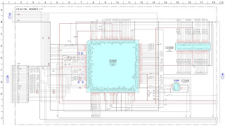
Digital board schematic

D-Amp board schematic
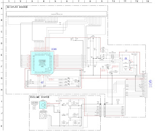
Display board schematic
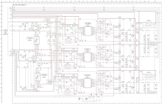
Power supply [SMPS] and speaker out section schematic

Sony HCD DX155, Sony HCD DX255 How to disassemble and reassemble the DVD mechanism, how to take out the disc when there is no power

$
0
0
Note on MAIN board replacement
New part of EEP ROM (IC1103) on the MAIN board cannot be used.
Therefore, if the mounted MAIN board (A-1151-985-A, etc.) is replaced, exchange new EEP ROM (IC1103) with that used before the replacement.
When displaying the version number on the screen
When you turn on the system, the version number [VER.X.XX] (X is a number) may appear on the screen. Although this is not a malfunction and for Sony service use only, normal system operation will not be possible.
Turn off the system, and then turn on the system again to operate.
When the self-diagnosis function is activated to prevent the system from malfunctioning, a 5- character service number (e.g., C 13 50) with a combination of a letter and 4 digits appears on the screen and the front panel display.
C 13: The disc is dirty.
Clean the disc with a soft cloth.
C 31: The disc is not inserted correctly.
Restart the system, then re-insert the disc correctly.
E XX (xx is a number): To prevent a malfunction, the system has performed the selfdiagnosis function.
Contact your nearest Sony dealer or local authorized Sony service facility and give the 5- character service number.
Example: E 61 10
The laser beam on this model is concentrated so as to be focused on the disc reflective surface by the objective lens in the optical pickup block. Therefore, when checking the laser diode emission,
observe from more than 30 cm away from the objective lens.
LASER DIODE AND FOCUS SEARCH
1. Open the cover and turn POWER on with no disc inserted.
2. Confirm that the following operation is performed while observing the objecting lens.
1)Confirm that laser beam is spread.
2)Up and down motion of the objective lens. (3 times)
DISC TRAY LOCK
The disc tray lock function for the antitheft of an demonstration disc in the store is equipped.
Setting Procedure :
1. Press the Power button to turn the set on.
2. Press the [FUNCTION] button to set DVD function.
3. Insert a disc.
4. Press the Stop button and the Eject  button simultaneously for five seconds.
5. The message “LOCKED” is displayed and the tray is locked.
Releasing Procedure :
1. Press the Stop button and the Eject  button simultaneously for five seconds again.
2. The message “UNLOCKED” is displayed and the tray is unlocked.
 When “LOCKED” is displayed, the tray lock is not released by turning power on/off with the Power button.
HOW TO OPEN THE DISC TABLE WHEN POWER SWITCH TURNS OFF
Fix the capacitors with adhesive agent as follows
Fixing the capacitors with adhesive agent is required by the safety regulation.
Be sure to fix the capacitors with adhesive agent when part or circuit board is replaced.
When installing a new op unit / precaution before unsoldering the static electricity prevention solder bridge
Be sure to connect the flexible printed circuit board first of all before removing the static electricity prevention solder bridge by unsoldering. Remove the static electricity prevention solder bridge by unsoldering after the flexible printed
circuit board has already been connected.
(Do not remove nor unsolder the solder bridge as long as the OP unit is kept standalone.)
Disassembly and reassembly of the DVD mechanism

Philips LX8200SA 22S AV System How to reprogram DVD version matrix. How to check the version matrix and firmware version number, power amplifier schematic

$
0
0
For repair information on the SD4.00SA DVD Module, refer to Service Manual "DVD Module SD-4.00SA_CH - 3122 785 12480".
For repair information on the Subwoofer SW8000SA/00S, refer to Service Manual "SW8000SA/00S/01S/17S - 3139 785 30099"
Output power (6 ohm, 1kHz, 10% THD) L & R, Center, Surround : 40W RMS / channel
Amplifier Frequency Response (-3dB) : 250Hz-32kHz
SOUND: JAZZ, ROCK, DIGITAL, CLASSIC [DRAMA, ACTION, SCI-FI, CONCERT]
[.....] Sound effect available when playing a DVD/VCD disc.
Input sensitivity
Aux in (at 1kHz) : 880mV ± 3dB
TV in (at 1kHz) : 350mV ± 3dB
Output sensitivity
Line out (Left/Right) : 0.6V ± 2dB at 100 kohm
Center out (Vol. Max.) : 500mV ± 2dB at 47 kohm
Subwoofer out (Vol. Max.) : 0.76V ± 2dB at 47 kohm
Headphone output at 32 ohm : 660mV ± 2dB (Vol. Max.)
Digital in : IEC 60958
Digital out : SPDIF Coaxial
Reprogramming of DVD version matrix [Only a qualified service person should do the reprogramming.]
After replacement/repair, the customer settings and also the region code may be lost.
Reprogramming will put the set back in the state in which it has left the factory, i.e. with the default settings and the allowed region code.
Reprogramming is done by the Remote Control.
Complete version matrix to be enter is
'PLAY 159 XXX XXX XX PLAY'
1) Ensure no disc is loaded in the tray.
2) Set the Remote Control to
DISC source.
3) Press <PLAY> followed by numerical keys <1> <5> <9>
Remark: Top left hand corner of the TV screen will display "X"for all these 4 keys that you have pressed.
4) Press now the following numerical keys (8 digits version matrix):
Remark: Nothing will be displayed on the TV screen for all these 8 digits that you have pressed.
for LX8200SA/22S : <2> <2> <2> <0> <3> <7> <0> <8>
5) Press <PLAY> again.
Caution: Wait for about 3 seconds for the set to reset to the required setting.
The TV screen will turn blue follow by a loud sound at the speaker output.
6) Disconnect mains to ensure proper reset.
How to check the version matrix and the software version number of the set:
1) Power up the set and select
DISC source.
2) Press <SYSTEM MENU> on the Remote Control to enter the User Preference Manual (UPM),
follow by pressing the following key:
-
<Cursor Down> key 4 times
-
<Cursor Right> key 1 time
-
<Cursor Down> key 4 times
3) Message "(C)PHILIPS 01- 02 5580 W.WW.WW ...... PXXXXXXXX Y.YY.Y"will be displayed
on the TV screen:
W.WW.WW
- indicate the BEA software version number
PXXXXXXXX - indicate the version matrix programmed
Y.YY.Y
- indicate the FEA (servo) software version number
4) Press <SYSTEM MENU> on the Remote control to exit.
Setting the TV system default
Press <SYSTEM MENU> on the Remote Control to enter the User Preference Manual (UPM).
2) From the User Preference Manual on the TV screen, select TV SYSTEM to change the TV system default
accordingly as shown in the table below:
Version
/21R
/21S
/22S
/30S
/33S
/37S
Region
Region 3
Region 4
Region 2
Region 4
Region 3
Region 1
TV system default
AUTO
NTSC
PAL
AUTO
AUTO
NTSC

3) Press <SYSTEM MENU> on the Remote control to exit.
Power amplifier board circuit diagram 

21HM 10F Sharp CRT TV How to enter the service mode, adjustments, schematic, troubleshooting, LED blinking codes

$
0
0
Sharp SEJB21HM10F00 SECAM B/G, L/L’ - PAL B/G SYSTEM COLOR TELEVISION, service mode, service mode adjustments, troubleshooting, full circuit diagram and more
The chassis in this receiver is partially hot. Use an isolation transformer between the line cord plug and power receptacle, when servicing this chassis.
To prevent electric shock, do not remove cover. No user-serviceable parts inside.
It is important that the static charge is removed from the high voltage system when carrying out work on the receiver. This can be achieved by connecting a 10K resistor (with a suitably insulated lead) from the CRT cavity connector to the CRT ground tag. This must be carried out with the AC supply disconnected from the receiver.
This receiver is designed to keep any x-ray emission to an absolute minimum. Some fault conditions and servicing procedures may produce potentially hazardous x-ray radiation levels. This is a problem when in close proximity to the receiver for long periods of time. To reduce any risks associated with this,  observe the following precautions:
1. When undertaking any servicing on this chassis, DO NOT increase the EHT to more than 30.5 KV, (at a instantaneous beam current of 1300)
2. Ensure that during normal operation the EHT does not exceed 25.0 KV +/- 1.5KV (at a beam current of 1100.) This level has been preset in the factory. Always check that this level has not been exceeded after carrying out any repair on the receiver.
3. DO NOT replace the CRT with any other type than that specified in the parts listing as this may cause excessive x-ray radiation.
White Level
Set the brightness control, with no signal connected, so that the CRT cathode current is 600mA. The maximum correction applied to each cathode current to achieve a screen temperature of 8900 degrees K-20 MPCD should not exceed 15% of its original value.
21-Pin Euro-scart pin details.
1. Audio right output
2. Audio right input
3. Audio left output
4. Common earth for audio
5. Earth for blue
6. Audio left input
7. Blue input
8. Audio-video control
9. Earth for green
10. Not used
11. Green input
12. Not used
13. Earth for red
14. Not used
15. Red input
16. Red/Green/Blue control
17. Earth for video
18. Earth for video
19. VIDEO output
20. VIDEO input
21. Common earth


Service mode function
All required adjustments for servicing this TV set, may be done in “Service Mode”, except G2 and FOCUS.
To access the service mode
1. Turn the receiver on and ensure that it is tuned into a test pattern.
2. Turn the receiver off using the mains switch.
3. Press the volume down and channel up buttons together.
4. Continue pressing the volume down and channel up buttons while turning the mains on using the mains switch. 
5. Keep pressing the volume down and channel up buttons until the picture appears.
6. When <<SHARPX X VXX.XX>> appears on the screen, release the two buttons.
7. The receiver is now in the service mode.
To move between the various service mode functions, use the channel up and down buttons. 
Use the volume buttons to change the data to the desired value. 
The data will be stored automatically when exiting the service mode. 
To exit the service mode press the standby button on the remote control or turn the receiver off with the mains switch.

Adjustments and data list
Heading:
OSD
Function
Description:
This is what will appear on the screen when at this position
This is the description of the mode’s function.
Range
Initial
Default
FIX/ADJ
This is the range of values that can be entered while in this mode.
This is the initial value, i.e. just after changing the NVM.
This is the recommended default value for this mode
If this is ADJ, then it may be necessary to adjust this value away from the default.

SCREEN ADJUSTMENTS
G2 Adjustment
1. Enter the service mode.
2. Use the channel up or channel down buttons to enter the << BLUE-BACK >> function.
3. Set this to << BLUE-BACK: 0 >>, i.e. blue background is turned off.
4. Turn the set off at the mains.
5. Turn the set back on.
6. Set the picture control settings to normal.
7. Select the SCART input by pressing the TV/SCART button on the remote control. Do not connect an input to the SCART socket. A blank raster will appear.
8. Connect an oscilloscope to TP851 on the CRT PWB. The waveform should be displayed.
9. Adjust the G2 control (screen voltage) so that the peak of this waveform is 3.0V +/-0.1V above the zero volt line.
10. Enter the service mode.
11. Turn the blue background function back on again - set << BLUE-BACK: 1 >>.
12. Turn off the receiver using the mains button.
13. The G2 adjustment is now complete.
Focus Adjustment.
1. Receive a monoscope pattern signal at a level of 60 to 80 dBV.
2. Set the picture settings to normal.
3. Adjust the focus potentiometer to obtain maximum definition.
AGC adjustment.
1. Tune the receiver into a colour bar signal on channel E-12.
2. Set the RF generator to an output signal strength of 57dBV (+/-1dBV) –50 Ohms unbalanced.
3. Connect an oscilloscope to TP201. TP201 is one end of R201.
4. Enter the service mode.
5. Use the channel up and channel down buttons to enter the AGC mode.
6. By using the volume up and the volume down buttons, adjust the AGC until the voltage on TP201 drops by 0.1V
to 0.3V below its maximum value.
7. Change the input signal strength to 66-70dBV and make sure that there is no noise apparent in the picture.
8. Turn the receiver off at the mains, this will exit the service mode and store the adjustment.
Geometry adjustment
1.Tune the set into a Philips test pattern.
2.Enter the service mode.
3.Use the channel up or channel down buttons to enter the desired mode.
4.Use the volume buttons to achieve correct setting.
5.When adjustments are complete, use the standby button to turn off the set. The adjustment values will be stored at this point.
V-LIN
Adjust the vertical linearity control so that the picture at the center of the screen.
V-AMP
Adjust the vertical amplitude control so that the picture over scans.
V-CENT
Adjust the vertical centering control so that the picture is centered.
H-CENT
Adjust the horizontal centring control so that the picture is centred.
colour adjustment.
This adjustment must be done after warming up the unit for 30 minutes or longer with a beam current over 700 µA.
The red value «DRI-RS» should be fixed to 42. (Refer to “How to access service mode”).
«DRI-GS» adjustment alters “Y” co-ordinate.
«DRI-BS» adjustment alters “X” and “Y” co-ordinates.
METHOD 1(using the signal generator, varying the picture signal)
Adjust G2.
2. Input a white pattern with burst signal from SCART.
3. Position the colorimeter in the centre of screen.
4. Adjusting input signal level, select a luminance of 70 nits.
5. Operate again in “service mode“ and select «DRI-GS» and/or «DRI-BS» locations to obtain colour co-ordinates:
6. Re-set the TV with the mains switch button to store the adjustment and exit service mode.
7.
Check color co-ordinates “X” and “Y” at 20 a 120 Nits. It may be necessary to repeat the same procedure to obtain the above values.
METHOD 2(using the signal generator, with a fixed picture signal)
1. Adjust G2.
2. Tune a white pattern with burst signal.
3. Operate in “service mode”:
4. Using «SUB-CON», select a luminance of 70 nits.
5. Operate again in “service mode“ and select «DRI-GS» and/or «DRI-BS» locations to obtain colour co-ordinates.
6. Select «SUB-CON». Return data to “63”.
7. Re-set the TV with the mains switch button to store the adjustment and exit service mode.
8.
Check colour co-ordinates “X” and “Y” at 20 a 120 Nits. It may be necessary to repeat the same procedure to obtain the above values.
LED flashing code
The led indicates the power mode, occurred I2C error and On timer
- Current power mode
- I2C Errors
- On timer
If in STANDBY mode and ON timer in-active then switch LED off.
- If in STANDBY and ON timer active set LED to blinking, (switch on and off at 1 Hz with a 50 % duty cycle).
- If in POWER-ON mode, switch LED on.
- If an I2C error occurred, let the LED blink at 1 Hz, 50 % duty cycle.
For the blinking times see the Table below.
Only when an I2C error occurs for a number of times, or for a number of seconds, the I2C error is handled by the system (that is ,only then the set will go to standby, the led starts blinking).
PIN configuration of TDA935X- [SDIP64]
Information:TDA9381 (IC801)
The function of pin 20, 28, 29, 31, 32, 35 and 44 is dependent on the IC version (mono intercarrier FM demodulator / QSS IF amplifier and East-West output or not) and on some software control bits.
The vertical guard function can be controlled via pin 49 or pin 50. The selection is made by means of the IVG bit in sub-address 2BH.
When additional (external) selectivity is required for FM-PLL system pin 32 can be used as sound IF input. This function is selected by means of SIF bit in sub-address 28H.
The reference output signal is only available for the CMB1/CMB0 setting of 0/1. For the other settings this pin is a switch output.
TEA1507-SMPS control IC details
SCHEMATIC AND TROUBLESHOOTING TABLES
Troubleshooting tables

SONY MULTI CHANNEL AV RECEIVER - STR-DA4300ES – Test modes – XM factory test mode – Special menu mode – Amplifier bias adjustment

$
0
0

SONY STR-DA4300ES TEST MODE

MEMORY CLEARING MODE
All preset contents are cleared when this mode is activated. Use this mode before returning the product to clients upon completion of repair.
Procedure:
1. While pressing the [TONE MODE] and [DMPORT] buttons, press the [POWER] button to turn on the main power.
2. The message “MEMORY CLEARING***” appears and the memories are reset to the default values.
3. When done, the message “MEMORY CLEARED*” appears.
FLUORESCENT INDICATOR TUBE PATTERN CHECK MODE
All fluorescent segments are tested. When this test is activated, all segments turn on at the same time, then each segment turns on one after another.
Procedure:
1. While pressing the [MOVIE] and [DMPORT] buttons, press the [POWER] button to turn on the main power.
2. All segments and all LEDs turn on.
SOUND FIELD CLEAR MODE
The preset sound field is cleared when this mode is activated. Use this mode before returning the product to clients upon completion of repair.
Procedure:
1. While pressing the [MUSIC] button, press the [POWER] button to turn on the main power.
2. The message “S. F. Initialize” appears and initialization is performed.
TUNER AM STEP CHANGE (9 kHz/10 kHz) MODE
Either the 9 kHz step or 10 kHz step can be selected for the AM channel step.
Procedure:
1. Press the [POWER] button to turn on the main power.
2. Turn the [INPUT SELECTOR] dial to select the “AM”.
3. Press the [POWER] button to turn off the main power.
4. While pressing the [TUNING MODE] button, press the [POWER] button to turn on the main power.
5. Either the message “AM 9kHz Step” or “AM 10kHz Step” appears, select the desired step.
COMMAND MODE CHANGE MODE
The command mode of the remote-commander which this set receives can be changed.
Procedure:
1. While pressing the [2CH/A. DIRECT] button, press the [POWER] button to turn on the main power.
2. Either the message “COMMAND MODE [AV1]” or “COMMAND MODE [AV2]” appears. Select the desired mode.
SF LOCK ON/OFF CHANGE MODE
Procedure:
1. While pressing the [MUSIC] and [DMPORT] buttons, press the [POWER] button to turn on the main power.
2. Either the message “SF LOCK [OFF]” or “SF LOCK [ON]” appears.

XM FACTORY TEST MODE
Mode to confirm operation of XM. Doing display of ID of XM antenna and output of audio signal that XM antenna generates, it is confirmed that there are no probrems in the communication of the XM antenna and the tranmission of the audio signal.
Procedure:
1. The XM antenna was connected, while pressing the [TUNING MODE] and [MOVIE] buttons, press the [POWER] button to turn on the main power.
2. Whenever the [DISPLAY] button is pressed, the output of the audio signal of 1 kHz L/R, 20 Hz L/R, 5 kHz L/R, muting, 1 kHz L and 1kHz R are switched.
SIRIUS FACTORY TEST MODE
Mode to confirm operation of SIRIUS. Doing display of ID of SIRIUS antenna and output of audio signal that SIRIUS antenna generates, it is confirmed that there are no probrems in the communication of the SIRIUS antenna and the tranmission of the audio signal.
Procedure:
1. The SIRIUS antenna was connected, while pressing the [TUNING MODE] and [A.F.D.] buttons, press the [POWER] button to turn on the main power.
2. Whenever the [DISPLAY] button is pressed, the output of the audio signal of 1 kHz L/R, 20 Hz L/R, 5 kHz L/R, muting, 1 kHz L and 1 kHz R are switched.

DIGITAL MEIDA PORT TEST
Procedure:
1. Connect the DMPORT check jig (P/N: J-2501-309-A) with the DMPORT jack (CN8003) on the TUNER board.
2. While pressing the [A.F.D.] and [DMPORT] buttons, press the [POWER] button to turn on the main power.
3. The message “DMPORT OK.” appears on the fluorescent indicator tube and enter the digital media port test mode. (Confirmation of communication line)
When “NO DETECT”, “UART NG” and “UART TO” are displayed on the fluorescent indicator tube, confirm the connection of the DMPORT check jig, and enter the mode again.
Each time the NEXT  button on the remote commander is pressed, the connect check and adaptor version check are switched.
Press the PREVIOUS button on the remote commander, connected confirmation of the DMPORT check jig is done again.
4. To a pinjack of the DMPORT check jig input information relevant to audio signal (sine-wave 1.0V rms) and composite video signal (white 100% 1.0Vp-p, color bar, etc.).
5. Confirm the output of speakers and monitor TV. (Confirmation of analog signal)
6. To exit from this mode, press the STOP  button on the remote.

HISTORY MODE
The state that the set is used is memorized.
Procedure:
1. While pressing the [MUSIC] and [MEMORY/ENTER] buttons, press the [POWER] button to turn on the power and “HISTORY MODE” is displayed.
2. Each time the UP/DOWN key of remote commander is pressed, the item is switched in order.

SPECIAL MENU MODE
Procedure:
1. Press the [POWER] button to turn on the main power, then while pressing the [TONE MODE] button, press the [A.F.D.], [2CH/A. DIRECT], [MUSIC], [MOVIE] button in order, the message “MENU SPECIALIZED!” appears.
2. Press the UP/DOWN  button of the remote commander, the message “<<< SPECIAL >>>” appears.

3. Press the RIGHT  button of the remote commander, the item is appears.
4. Each time the UP/DOWN  button of the remote commander is pressed, the item is switched in order as follows. Some items can change the content. Display the cursor by pressing the RIGHT  button of the remote commander, and changing the content by pressing the UP/DOWN  button of the remote commander, and fix the content by pressing the LEFT  button of the remote commander when you want to change the content of the item.
5. To release from this mode, while pressing the [TONE MODE] button, press the [A.F.D.], [2CH/A. DIRECT], [MUSIC], [MOVIE] button in order again, the message “MENU SPECIALIZED OFF” appears.

BIAS ALIGNMENT ADJUSTMENT
Note: Afer 10 minutes or more have passed since the power supply was turned on, this adjustment is done.
Connection:

CN1561 (CN1611, CN1761, CN1861) pin 1, CN1561 (CN1761, CN1861) pin 3
CN1561 (CN1611, CN1761, CN1861) pin 2, CN1561 (CN1761, CN1861) pin 4

Procedure:
1. Connect a digital voltmeter to the CN1561 (CN1611, CN1761,
CN1861).
2. Press the [POWER] button to turn on the main power.
3. Adjust the RV1501 (RV1551, RV1601, RV1701, RV1751, RV1801, RV1851) so that the digital voltmeter reading is 5 Mv to 20 mV.


BOSE SoundTouch Wireless Adapter – air play and non air play – WiFi module test - factory reset - USB port test - disassembling – teat procedure

$
0
0

BOSE SoundTouch Wireless Adapter DISASSEMBLY PROCEDURES

1. Top Cover Removal
1.1 With the unit upside down, remove the three screws that secure to two halves of the enclosure together.
1.2 Lift off the bottom enclosure. It will come off with the Wi-Fi PCB assembly mounted in the bottom of it, attached to the I/O board with two ribbon cables. The I/O PCB assembly is mounted to the upper enclosure plastic.

2. I/O PCB Assembly Removal
2.1 Perform procedure 1.
2.2 Remove the two screws that secure the I/O PCB assembly to the upper housing. Lift out the board.
Note: Retain the connector scrim and the reset button scrim for re-use.
2.3 Disconnect the Bose link cable at J201. Disconnect the ribbon cables and J200 and J300.
Note: The Bose link cable is not easily replaceable. It comes as a service part, included with the top housing, pressed in place.

3. Wi-Fi Module PCB Removal
3.1 Perform procedure 1.
3.2 Remove the one screw that secures the Wi-Fi board to the bottom housing. Lift out the PCB assembly.
3.3 Disconnect the two ribbon cables at J1201 and J1203.
Note: Due to complexity, the Wi-Fi module PCB assembly is not repairable at the component level. If you suspect it has failed, you will need to replace the board.

TAP COMMAND SETUP

Note: The SoundTouch wireless adapter is powered by +12 over its Bose link cable. You will need to connect the wireless adapter to a compatible SoundTouch product such as an SA-4 amplifier, Stereo JC music system bass module or a Lifestyle SoundTouch media center in order to provide power to it for the following tests.
TAP command setup
Equipment Required:
Hardware
# Computer w/serial port
# RS232 to TTL converter
# Lifestyle ETAP Cable, P/N 264565
# SoundTouch product, SA-4 amplifier or other compatible
Software
# TeraTerm terminal emulator 
TAP commands are sent to the SoundTouch wireless adapter by connecting to the SERVICE connector on the back of the adapter. An ETAP cable and RS232 to TTL Converter are required for this communication. The ETAP cable is available from Bose  (see part number above). The RS232 to TTL Converter is made by B+B electronics, model number 232LPTTL. TAP commands are needed for the following procedures:

A. Wi-Fi Test
B. Serial Number Programing
C. Setting Wi-Fi Country Code
1. Tera Term Terminal USB Setup
Tera Term is a terminal emulator and can be downloaded at sourceforge  projects/ttssh2/. It is the interface used to send TAP commands to the SoundTouch wireless adapter.
1.1 Connect the SoundTouch wireless adapter to the computer.
# Connect the RS-232 to TTL converter to the COM port on the PC. 
# Connect the TAP cable to the RS-232 to TTL converter.
# Plug the other end of the TAP cable into the SERVICE jack on the back of the SoundTouch wireless adapter.
# Connect the SoundTouch wireless adapter Bose link cable to the SoundTouch product.
# Connect the SoundTouch product to AC power.
2. Teraterm Setup
2.1 Launch a Tera Term terminal window and select serial communication and port

2.2 Select setup, then serial port to set the
baud rate to 115,200 data to 8 bit, parity to
none, stop to 1 bit and flow control to none.

3. Test TAP Communication
3.1 Enter TAP command “sys ver”. The system will respond with the software version similar to: BoseApp version: 1.0.17.11330.242810 epdbuild.rel_1.x.hepdswbld05.2013-06- 18T15:50:19.
Functional Tests
Note: The SoundTouch wireless adapter is powered by +12 over its Bose link cable. You will need to connect the wireless adapter to a compatible SoundTouch product such as an SA-4 amplifier, Stereo JC music system bass module or a Lifestyle SoundTouch media center in order to provide power to it for the following tests.

1. Wi-Fi Functional Test Set Up
This test uses TAP commands to connect the product to a Wi-Fi network and stream audio from a Bose . The Bose SoundTouchTM application can be used in place of this test.
Note: Do not download the audio file from the test URL. Determine the security type for your router and select the appropriate TAP command for connecting to a Wi-Fi Router (WEP, WPA, or no security).

2. Connecting to a Wi-Fi Router
2.1 Enter the following TAP command for your router security type setting. Do not enter parentheses.
2.1.1 WEP Security Type  airplay wep profile (SSID) (Password)
2.1.2 WPA Security Type airplay wpa profile (SSID) (tkip or aes) (Password)
2.1.3 No Security airplay Wi-Fi profile (SSID)
2.2 Wait for the Wi-Fi indicator LED on the back of the unit to turn white. This may take up to a minute. While the unit is connecting, it will flash amber. If the indicator does not turn white, enter the TAP command again.
3. Testing the Wi-Fi Module.
3.1 Enter the following TAP commands. Press the <enter> key on your keyboard after each command. You should see an OK response in the Tera Term dialog box. sys configuration DemoAudioURL worldwide.bose.com/downloads/assets/ audio/take5.mp3 <enter> sys configuration DemoNetworkEnabled true <enter> demo enter <enter>
3.2 The song “Take 5” should play. Listen for clean undistorted audio.
3.3 Enter the following TAP command to exit the Wi-Fi test. demo exit <enter>
Note: A Tera-Term macro that includes these TAP commands is available for download on the product’s repair information page. Place the macro file in the same folder as your Tera-Term program. Open Tera-Term, select Control, Macro, wifi_test.ttl. Once the macro runs, follow the prompts.
4. Factory Default Unit
4.1 Enter the TAP command sys factorydefault <enter>
4.2 Provide the customer instructions for reconnecting their system to their Wi-Fi network. Download the instructional sheet on the product’s repair information page.
5. USB Port Test
5.1 Connect the SoundTouch wireless adapter to a computer as shown in the TAP command set up documented.
5.2 Type the command “local_services on” and <enter>. Then press CTRL-C on the keyboard. Then type “e” and <enter>. The command line lisa login: should be displayed on the computer.
5.3 Type the command “root” and <enter>. The command line should be root@lisa:root#.
5.4 Connect a USB thumb drive to the USB port located on the back of the product.

5.5 Type the command “lsusb”.
5.6 Verify the unit responds with the name of the USB thumbdrive. Sample response - Bus 002 Device 002: ID 0781:5151 SanDisk Corp. Cruzer Micro Flash Drive.
5.7 Send the command “rm /mnt/nv/ local_services” and <enter>.
5.8 Send the command “exit” and <enter>. This will return to the TAP interface (CLI) and a TAP command line “->” should be shown.
6. Micro USB Port Test
6.1 Using a micro USB to standard USB cable, insert the micro USB end of the cable into the SoundTouch connector labeled SETUP A (micro USB). Plug the other end of the cable into a USB port on a computer. Ensure that cable is properly seated.
6.2 Open your device manger and look under Network Adapters. You should see the SoundTouch Wi-Fi adapter as an adapter.
Directions: On your computer, click on Start and navigate to Run. In the window that opens, enter “mmc devmgmt.msc”. The device manager will open. In the device manager, expand the network adapters, you should see the SoundTouch wireless adapter as an adapter.
7. Ethernet Connector Test
7.1 Insert an Ethernet cable into the Ethernet connector on the SoundTouch system. Connect the other end of the cable to the router.
7.2 The LED lights on the product’s Ethernet connector should light up yellow and green after a few seconds indicating that the connector is functioning.


Sony Trinitron KV-SP29M53K - Service mode, Service adjustments, full Schematic, Disassemble procedure, self diagnosis function details

$
0
0

Sony Trinitron KV-SP29M53K- RM-GA002, KV-SP29M83K- RM-GA002, KV-SP29N63K- RM-GA002 – Service mode, Service adjustments, full Schematic, Disassemble procedure

Self-diagnostic function.
If an error occurs, the STANDBY Indicator will automatically begin to flash.
The number of times the STANDBY Indicator flashes translates to a probable source of the problem.If an error symptom cannot be reproduced, the remote commander can be used to review the failure occurrence data stored in memory to reveal past problems and how often these problems occur.
Result for all of the following diagnostic items are displayed on screen. No error has occured if the screen displays a “0”.

HANDLING SELF DIAGNOSTIC SCREEN DISPLAY
OCP - +B overcurrent - Occurs when an overcurrent on the +B(135V) line is detected by pin 32 of IC001 (A board). 
 If the voltage of pin 32 of IC001 (A board) is more than 4V, the unit will automatically go to standby.
V-Protect - Occurs when an absence of the vertical deflection pulse is detected by pin 13 of IC001 (A board).
IK (AKB) - If the RGB levels do not balance for 15 sec after the power is turned on, this error will be detected by IC001 (A board). 
TV will stay on, but there will be 5 times LED blinking.
Power supply NG (+5V) for video processor - Occurs when IC001 internal HV protect detects an abnormal H-Pulse (frequency) due to improper power supply to IC001. TV cuts off high voltage power of anode CRT. 
No picture will be detected. eg: IC602, IC604 go faulty.
Disassembly procedure
Entering service mode and adjustments.
ADJUSTMENT WITH COMMANDER.
Service adjustments to this model can be performed using the supplied remote commander RM-GA002.
ENTERING SERVICE MODE
METHOD OF CANCELLATION FROM SERVICE MODE
Set the standby condition (Press [POWER] button on the commander), then press [POWER] button again, hereupon it becomes TV mode.
METHOD OF WRITE INTO MEMORY.
Set to Service Mode.
2. Press 1 (UP) and 4 (DOWN), to select the adjustment item.
3. Change item by pressing 3 & 6.
4. Press [MUTING] button to indicate WRITE on the screen.
5. Press (-) button to write into memory.
MEMORY WRITE CONFIRMATION METHOD.
1. After adjustment, pull out the plug from AC outlet, and then plug into AC outlet again.
2. Turn the power switch ON and set to Service Mode.
3. Call the adjusted items again to confirm adjustments were made.
Other functions via remote control.
ADJUSTMENT METHOD.
Item Number 000 HPOS (Horizontal Position).
This explanation uses H POSITION as an example.
1. Select "000 HPOS" with the 1 and 4 buttons, or 2 and 5.
2. Raise/lower the data with the 3 and 6 buttons.
3. Select the optimum state. (The standard is IF for PAL reception.)
4. Write with the [MUTING] button. (The display changes to WRITE.)
5. Execute the writing with the - button. (The WRITE display will be changed to red color while executing, and back to SERVICE.)
Use the same method for all Items. 
Use 1 and 4 to select the adjustment item, use 3 and 6 to adjust, write with [MUTING], then execute the write with (-)
In [WRITE], the data for all items are written into memory together.
2. For adjustment items that have different standard data between 50Hz or 60Hz, be sure to use the respective input signal after adjustment.
PICTURE QUALITY ADJUSTMENT. 
1. Set TV to Video mode.
2. Set Picture mode to “CUSTOM”.
3. Input PAL 100% Color Bar to TV set (OTHER model) and NTSC 75% Color Bar (NTSC model).
4. Set the following condition:
Picture 100%, Color 0%, Brightness 50%.
5. Connect an oscilloscope to pin 4 (R output) of CN004.
6. Go to service mode and set PICT 003 “PWL” to 00h and WHBL 017 “BLBG” to 01h and PICT 002 “SOC” to 03.
7. Select SADJ 000 “PMAX” with 1 and 4 button of the commander then adjust VR with spec with 3 and 6 button until reach the spec below:
8. Then copy the adjusted PMAX data to TV mode.
9. Select Wide mode to “ON” in TV and Video mode and write “PMAX” data -6 steps (for models with V-Compression features only).
10. Press [MUTING] t - to write the data.
11. Set “PWL” and “BLBG” back to initial data.
(“PWL” : 01h “SOC” : 00 and “BLBG” : 00h).
12. Finally press [MUTING] ( - ) to write the data.
SUB COLOR ADJUSTMENT
1. Set TV to Video mode.
2. Set Picture mode to “CUSTOM”.
3. Input PAL 100% Color Bar to TV.
4. Set the following condition:
Picture 100%, Color 50%, Brightness 50%, Hue 50% and Sharpness 50%.
5. Set PICT 006 “WTS” to 00h.
6. Connect an oscilloscope to pin 2 (B output) of CN004 A Board.
7. Select SADJ 004 “SCOL” with 1 and 4 button of the commander then adjust with 3 and 6 so that VB2=VB3=VB4 (for PAL) then write in the data as below:
(Add 11 steps to “SCOL” (PAL) – 25"
Add 11 steps to “SCOL” (PAL) – 29"
Add 6 steps to “SCOL” (PAL) – 34")
8. Copy “SCOL” 50(PAL) video data to “SCOL” 50 (SECAM) video.
9. Then copy “SCOL” 50(PAL) video data and “SCOL” 50(SECAM) video data to “SCOL” 50(PAL) and “SCOL” 50(SECAM) TV table.
10. For NTSC model input NTSC 75% Color Bar to TV and repeat step no. 4 to 6.
11. Select SADJ 004 “SCOL” with 1 and 4 button of the commander then adjust using 3 and 6 so that VB1=VB4 then write in the data.
12. Copy “SCOL” 60(NTSC) video data to “SCOL” 60(NTSC) TV .
13. Finally copy “SCOL” 50(PAL) and “SCOL” 60(NTSC) data to “SCOL” 50(PAL) and 60(NTSC) in DVD mode.
14. Then press [MUTING] t - to write the data.
15. Set PICT 006 “WTS” back to original data.
SUB HUE ADJUSTMENT.
Set TV to Video mode.
2. Input NTSC 3.58 Color Bar to TV set.
3. Set the following condition:
Picture 100%, Color 50%, Brightness 50%, Hue 50%, Sharpness 50%.
4. Connect oscilloscope to pin 2 (B output) of CN004.
5. Set to service mode and select YC 013 "TINT" with 1 and 4 button then adjust to VB1=VB2=VB3=VB4 using 3 and 6 button.
6. Press [MUTING] ( - ) to write the data.
7. Select TV channel with NTSC 3.58 and perform step 3 to 6.
8. For single system model with NTSC 4.43, select TV channel with NTSC 4.43 and perform step 3 to 6.
9. Once adjustment is completed in Video mode, carry out adjustment in DVD mode. Input NTSC 3.58 Color Bar.
10. Connect oscilloscope to pin 2 (B output) of CN004.
11. Set to service mode and adjust service item YC 013 “TINT” with 1 and 4 button until VB1=VB2=VB3=VB4.
12. Press [MUTING] (-) to write the data.
(The highest level of VB1, VB2, VB3 and VB4 should be aligned at the same line.  The ideal difference between VB2 and VB3 is within + 80mV.)
SUB BRIGHT ADJUSTMENT.
1. Set TV to RF mode.
2. Input PAL monoscope to RF mode (OTHER model) and NTSC monoscope (NTSC model).
3. Set Brightness to 50% and Picture to “MINIMUM” in "CUSTOM" mode.
4. Select WHBL 010 “SBRT” with 1 and 4 button and adjust its data using 3 and 6 button so that the Cut Off level and slightly glimmer is as the specification below:
5. Write into the memory by pressing [MUTING]  (-)
6. Copy the adjusted data WHBL 010 “SBRT” to Video mode.
7. Once adjustment is completed in RF and Video mode, carry out adjustment in DVD mode. Repeat step 2 to 3.Select WHBL 010 “SBRT” and adjust its data.
GEOMETRY ADJUSTMENT
H-TRAPEZOID ADJUSTMENT.
1. Receive cross hatch/dot signal.
2. Adjust RV1800 on C Board to make H-Trapezoid distortion best/to obtain the center illustration shown in Table.
NORMAL MODE 50Hz / 60Hz
1. Input PAL Special Color Bar (SPCB) or PAL Monoscope (OTHER model) and Video mode or NTSC Monoscope (NTSC model) signal using a pattern generator.
2. Set Wide Mode to “OFF”.
3. Select Category items listed in Table 1.
4. Raise and Lower the data value using 3 and 6 button to obtain the center illustration.
5. Press [MUTING] (-)to save the data into the memory.
6. For Korea models, copy adjusted 60Hz to 50Hz. Add 6 steps to 50Hz “HPOS” and 3 steps to 50Hz “HSIZ” and save the data.
WIDE MODE 50Hz / 60Hz (V Compression Adjustment)
1. Input PAL Special Color Bar (SPCB) (OTHER model) or Monoscope NTSC (NTSC model) signal using a pattern generator.
2. Set Wide Mode to “ON”.
3. Copy NORMAL MODE 50Hz/60Hz adjusted data for the following items:-
GEOM: 011 VSIZ, 010 VSLP, 012 SCOR and 003 VLIN
4. Select Category items listed in Table 1 except GEOM:
003 VLIN, 010 VSLP, 011 VSIZ, and 012 SCOR and
adjust the data to obtain the center illustration.
5. Press [MUTING]  (-)to save the data into the memory.
6. For Korea models, copy adjusted 60Hz to 50Hz. Add 6 steps to 50Hz “HPOS” and save the data.
                    Schematic full

BOSE SoundTouch Wireless Adapter – air play and non air play – WiFi module test - factory reset - USB port test - disassembling – teat procedure

$
0
0

BOSE SoundTouch Wireless Adapter DISASSEMBLY PROCEDURES

1. Top Cover Removal
1.1 With the unit upside down, remove the three screws that secure to two halves of the enclosure together.
1.2 Lift off the bottom enclosure. It will come off with the Wi-Fi PCB assembly mounted in the bottom of it, attached to the I/O board with two ribbon cables. The I/O PCB assembly is mounted to the upper enclosure plastic.

2. I/O PCB Assembly Removal

2.1 Perform procedure 1.
2.2 Remove the two screws that secure the I/O PCB assembly to the upper housing. Lift out the board.
Note: Retain the connector scrim and the reset button scrim for re-use.
2.3 Disconnect the Bose link cable at J201. Disconnect the ribbon cables and J200 and J300.
Note: The Bose link cable is not easily replaceable. It comes as a service part, included with the top housing, pressed in place.

3. Wi-Fi Module PCB Removal
3.1 Perform procedure 1.
3.2 Remove the one screw that secures the Wi-Fi board to the bottom housing. Lift out the PCB assembly.
3.3 Disconnect the two ribbon cables at J1201 and J1203.
Note: Due to complexity, the Wi-Fi module PCB assembly is not repairable at the component level. If you suspect it has failed, you will need to replace the board.

TAP COMMAND SETUP

Note: The SoundTouch wireless adapter is powered by +12 over its Bose link cable. You will need to connect the wireless adapter to a compatible SoundTouch product such as an SA-4 amplifier, Stereo JC music system bass module or a Lifestyle SoundTouch media center in order to provide power to it for the following tests.
TAP command setup
Equipment Required:
Hardware
# Computer w/serial port
# RS232 to TTL converter
# Lifestyle ETAP Cable, P/N 264565
# SoundTouch product, SA-4 amplifier or other compatible
Software
# TeraTerm terminal emulator 
TAP commands are sent to the SoundTouch wireless adapter by connecting to the SERVICE connector on the back of the adapter. An ETAP cable and RS232 to TTL Converter are required for this communication. The ETAP cable is available from Bose  (see part number above). The RS232 to TTL Converter is made by B+B electronics, model number 232LPTTL. TAP commands are needed for the following procedures:

A. Wi-Fi Test
B. Serial Number Programing
C. Setting Wi-Fi Country Code
1. Tera Term Terminal USB Setup
Tera Term is a terminal emulator and can be downloaded at sourceforge  projects/ttssh2/. It is the interface used to send TAP commands to the SoundTouch wireless adapter.
1.1 Connect the SoundTouch wireless adapter to the computer.
# Connect the RS-232 to TTL converter to the COM port on the PC. 
# Connect the TAP cable to the RS-232 to TTL converter.
# Plug the other end of the TAP cable into the SERVICE jack on the back of the SoundTouch wireless adapter.
# Connect the SoundTouch wireless adapter Bose link cable to the SoundTouch product.
# Connect the SoundTouch product to AC power.
2. Teraterm Setup
2.1 Launch a Tera Term terminal window and select serial communication and port

2.2 Select setup, then serial port to set the
baud rate to 115,200 data to 8 bit, parity to
none, stop to 1 bit and flow control to none.

3. Test TAP Communication
3.1 Enter TAP command “sys ver”. The system will respond with the software version similar to: BoseApp version: 1.0.17.11330.242810 epdbuild.rel_1.x.hepdswbld05.2013-06- 18T15:50:19.
Functional Tests
Note: The SoundTouch wireless adapter is powered by +12 over its Bose link cable. You will need to connect the wireless adapter to a compatible SoundTouch product such as an SA-4 amplifier, Stereo JC music system bass module or a Lifestyle SoundTouch media center in order to provide power to it for the following tests.

1. Wi-Fi Functional Test Set Up
This test uses TAP commands to connect the product to a Wi-Fi network and stream audio from a Bose . The Bose SoundTouchTM application can be used in place of this test.
Note: Do not download the audio file from the test URL. Determine the security type for your router and select the appropriate TAP command for connecting to a Wi-Fi Router (WEP, WPA, or no security).

2. Connecting to a Wi-Fi Router
2.1 Enter the following TAP command for your router security type setting. Do not enter parentheses.
2.1.1 WEP Security Type  airplay wep profile (SSID) (Password)
2.1.2 WPA Security Type airplay wpa profile (SSID) (tkip or aes) (Password)
2.1.3 No Security airplay Wi-Fi profile (SSID)
2.2 Wait for the Wi-Fi indicator LED on the back of the unit to turn white. This may take up to a minute. While the unit is connecting, it will flash amber. If the indicator does not turn white, enter the TAP command again.
3. Testing the Wi-Fi Module.
3.1 Enter the following TAP commands. Press the <enter> key on your keyboard after each command. You should see an OK response in the Tera Term dialog box. sys configuration DemoAudioURL worldwide.bose.com/downloads/assets/ audio/take5.mp3 <enter> sys configuration DemoNetworkEnabled true <enter> demo enter <enter>
3.2 The song “Take 5” should play. Listen for clean undistorted audio.
3.3 Enter the following TAP command to exit the Wi-Fi test. demo exit <enter>
Note: A Tera-Term macro that includes these TAP commands is available for download on the product’s repair information page. Place the macro file in the same folder as your Tera-Term program. Open Tera-Term, select Control, Macro, wifi_test.ttl. Once the macro runs, follow the prompts.
4. Factory Default Unit
4.1 Enter the TAP command sys factorydefault <enter>
4.2 Provide the customer instructions for reconnecting their system to their Wi-Fi network. Download the instructional sheet on the product’s repair information page.
5. USB Port Test
5.1 Connect the SoundTouch wireless adapter to a computer as shown in the TAP command set up documented.
5.2 Type the command “local_services on” and <enter>. Then press CTRL-C on the keyboard. Then type “e” and <enter>. The command line lisa login: should be displayed on the computer.
5.3 Type the command “root” and <enter>. The command line should be root@lisa:root#.
5.4 Connect a USB thumb drive to the USB port located on the back of the product.

5.5 Type the command “lsusb”.
5.6 Verify the unit responds with the name of the USB thumbdrive. Sample response - Bus 002 Device 002: ID 0781:5151 SanDisk Corp. Cruzer Micro Flash Drive.
5.7 Send the command “rm /mnt/nv/ local_services” and <enter>.
5.8 Send the command “exit” and <enter>. This will return to the TAP interface (CLI) and a TAP command line “->” should be shown.
6. Micro USB Port Test
6.1 Using a micro USB to standard USB cable, insert the micro USB end of the cable into the SoundTouch connector labeled SETUP A (micro USB). Plug the other end of the cable into a USB port on a computer. Ensure that cable is properly seated.
6.2 Open your device manger and look under Network Adapters. You should see the SoundTouch Wi-Fi adapter as an adapter.
Directions: On your computer, click on Start and navigate to Run. In the window that opens, enter “mmc devmgmt.msc”. The device manager will open. In the device manager, expand the network adapters, you should see the SoundTouch wireless adapter as an adapter.
7. Ethernet Connector Test
7.1 Insert an Ethernet cable into the Ethernet connector on the SoundTouch system. Connect the other end of the cable to the router.
7.2 The LED lights on the product’s Ethernet connector should light up yellow and green after a few seconds indicating that the connector is functioning.


BOSE SoundTouch 30 Series I & II Test procedure, Tap command setup, Hi pot test – wifi test procedure

$
0
0

BOSE SoundTouch 30 Series I & II  AUDIO TEST PROCEDURES

Functional Tests
Equipment Required
Audio Signal Generator
Notes:
1. Begin the test with no power applied.
2. Confirm the Audio Signal Generator output is set to zero volts before connecting.
1. Twiddler Air Leak Test
1.1 Connect the audio signal generator to the mini jack AUX input on the back of SoundDock 10.
1.2 Set the signal generator output to:
A. Voltage = 0V
B. Frequency = 250Hz +/- 10%
1.3 Apply power to the SoundTouch 30 and select AUX. Set volume to 60% by using the volume control.
1.4 Set the Signal generator output to:
A. Input Voltage = 1.0Vrms +/- 10%
B. Frequency = 250Hz +/- 5Hz
1.5 Listen for air leaks around all the cabinet seams, joints, and wire harness throughholes.
PASS if no audible air leaks can be heard at a distance of less than 1ft (0.3M) from any exterior surface of the enclosure.
FAIL if any air leaks can be heard at a distance less than 1ft (0.3M) from any exterior surface of the enclosure.

2. Woofer Air Leak Test
2.1 Set the signal generator output to:
A. Input Voltage = 0.570 Vrms +/- 10%
B. Frequency = 44Hz +/- 5Hz
2.2 Listen for air leaks around all the cabinet seams, joints, and wire harness throughholes.
PASS if no audible air leaks can be heard at a distance of less than 1ft (0.3M) from any exterior surface of the enclosure.
FAIL if any air leaks can be heard at a distance less than 1ft (0.3M) from any exterior surface of the enclosure.
3. Left / Right Driver Test
3.1 Apply an input signal to the SoundTouch left channel only. Set generator as in step 1.3 and 1.4, except set the frequency to 800Hz and confirm that only the left driver plays.
3.2 Reduce generator output to zero volts
3.3 Repeat step 3.1 for the right channel.
3.4 Reduce input signal to zero volts and reconnect the right channel.
4. Frequency Sweep Test
4.1 Set audio signal generator to:
A. Voltage = 0.06 Vrms +10%
B. Sweep range = 35Hz - 3KHz +10%
4.2 Execute the sweep for a minimum of 3 seconds up and 3 seconds down.
4.3 Listen for any extraneous noises such as buzzes, rattles, ticks, and distortion.
PASS if no noise can be heard at a distance of less than 1ft (0.3M).
FAIL if any noise can be heard at a distance less than 1ft (0.3M).
4.4 Reduce the input signal to zero volts.

AP COMMAND SET UP

TAP command set up
Equipment Required
Hardware
Computer w/serial port
RS232 to TTL converter
Lifestyle ETAP Cable, P/N 264565
Soundlink ETAP adapter P/N 347062-0005
Software
TeraTerm terminal emulator
(Download at sourceforge.jp/projects/ ttssh2/)
Notes: TAP commands can be sent to the SoundTouch 30 system by connecting a PC to the AUX IN connector. An ETAP cable, ETAP Cable adapter and RS232 to TTL Converter are required for this communication. Both ETAP cables are available from Bose (see part numbers above). The RS232 to TTL Converter is made by B+B electronics, model number 232LPTTL.

TAP commands are needed for the following
procedures:
A. WiFi Link Test
B. Serial Number Programing
C. Setting WiFi Country Code

1. Tera Term Terminal USB set up
Tera Term is a terminal emulator and can be downloaded at sourceforge.jp/projects/ ttssh2/. It is the interface used to send commands to the SoundTouch 30 product.
1.1 Connect the SoundTouch as shown in the diagram below.

2. Teraterm set up
2.1 Launch a Tera Term terminal window and select serial communicaton.

2.2 Select setup, then serial port to set the baud rate to 115,200 data to 8 bit, parity to none, stop to 1 bit and flow control to none.

2.3 Connect power to the SoundTouch 30. The product will boot, and the Tera Term window will display the boot information

WI-FI TEST PROCEDURE

1. Wi-Fi Functional Test Set Up
This test uses TAP commands to connect the product to a Wi-Fi network and stream audio from a Bose URL. The Bose SoundTouchTM application can be used in place of this test.
Note: Do not download the audio file from the test URL. Determine the security type for your router and select the appropriate TAP command for Connecting to a Wi-Fi Router. (WEP, WPA, or no security)
2. Connecting to a Wi-Fi Router
2.1 Enter the following TAP command for your router security type setting. Do not enter parentheses.
2.1.1 WEP Security Type airplay wep profile (SSID) (Password)
2.1.2 WPA Security Type airplay wpa profile (SSID) (tkip or aes)
(Password)
2.1.3 No Security
airplay Wi-Fi profile (SSID)
2.2 Wait for the Wi-Fi indicator on the product’s display to turn solid white. This may take up to a minute. If the indicator does not turn white, enter the TAP command again.
3. Testing the Wi-Fi Module.
3.1 Enter the following TAP commands. sys configuration DemoAudioURL worldwide.bose /downloads/assets/audio/take5.mp3 sys configuration DemoNetworkEnabled true demo enter
3.4 The song “Take 5” should play. Listen for clean undistorted audio.
3.5 Enter the following TAP command to exit the Wi-Fi test. demo exit
Note: A Tera-Term macro that includes these TAP commands is available for download on the product’s repair information page. Place the macro file in the same folder as your Tera-Term program. Open Tera-Term, select Control, Macro, wifi_test.ttl. Once the macro runs, follow the prompts.
4. Factory Reset.
4.1 Factory default the system by sending the “sys factorydefault” command or press “volume -” and “preset 1”.

FUNCTIONAL TEST PROCEDURES

Miscellaneous Tests
1. IR Remote Test
1.1 Confirm power is applied.
1.2 Press each button on the remote control confirming the display reacts to each button press.
2. Keypad Button Test
2.1 Confirm power is applied to the SoundTouch 30.
2.2 Press each button the SoundTouch 30 keypad confirming the display reacts to each button press.
3. USB Port Functional Test
3.1 Connect the SoundTouch 30 to a computer as shown in the TAP command set up documented on pages 23 and 24.
3.2 Type the command “local_services on” and <enter>. Then press CTRL-C on the keyboard. Then send the command “e” and <enter>. A command line mojo login: should be displayed on the computer.
3.3 Type the command root and <enter>. This will cause the command line to change to root@mojo:root#.
3.4 Connect a USB thumb drive into the USB port located on the back of the product.
3.5 Type the command “lsusb”.
3.6 Verify the USB memory stick lights up and the name of the USB memory stick is visible.
3.7 Send the command “rm /mnt/nv/ local_services” and <enter>.
3.8 Send the command “exit” and <enter>. This will return to the TAP interface (CLI) and a TAP command line “->” should be shown.

4. Micro USB Port Functional Test
4.1 Using a micro USB to standard USB cable, insert a micro USB end of the cable into the SoundTouch connector labeled SETUP A (micro USB). Plug the other end of the cable into a USB port on the computer. Ensure that cable is properly seated.


4.2 Open your device manger and look under Network Adapters. You should see the SoundTouch 20 as an adapter. Directions: On your computer, click on Start and navigate to Run. In the window that opens, enter “mmc devmgmt.msc”. The device manager will open. In the device manager, expand the network adapters, you should see the SountTouch 30 as an adapter.
5. Ethernet Connector Functional Test
5.1 Insert an Ethernet cable into the Ethernet connector on the SoundTouch system. Connect the other end of the cable to the router.

5.2 The LED lights on the Ethernet connector from the SoundTouch should light up yellow and green after a few seconds indicating that this connector is functioning.

SERIAL NUMBER AND COUNTRY CODE PROGRAMING

Perform both of these procedures any time the Wi-Fi Module is replaced. Download two macros from the SoundTouch product’s repair information page located on serviceops.bose.Place these macros in the Tera Term program folder.
set_serial_number.ttl
set_country_code.ttl
1. Setting the Serial Number
1.1 Connect the SoundTouch to a computer
1.2 Within Tera Term, select Control then
Macro and Select the file -
“set_serial_number.ttl”
1.3 Follow the prompts.
Note: The serial number can be read by pressing the Volume - button and the number
5 at the same time for 5 seconds for system information. Use the Volume - and + button to toggle through system information.
2. Setting the Country Code
2.1 Connect the SoundTouch Portable to a computer as shown in the TAP command set up procedure on pages 30 and 31.
2.2 Within Tera Term, select Control then Macro and Select the file - “set_country_code.ttl”
2.4 Follow the prompts.
Note: Selecting us sets the Wi-Fi module to the US standard channels 1-11. Selecting eu sets the Wi-Fi module to EU standard channels 1-13

3. Reading the Country Code.
3.1 Type the command “local_services on” and <enter>. Then press CTRL-C on the keyboard. Then type “e” and <enter>. The command line mojo login: should be displayed on the computer.
3.2 Type the command “root” and <enter>. The command line should be root@mojo:root#.
3.3 Enter “cat /var/tmp/mfgdata.xml”. The country code is displayed in the first line of the response.
3.4 Return to CLI prompt by entering the command “rm /mnt/nv/local_services” and <enter>.
3.5 Enter the command “exit” and <enter>. This will return to the TAP interface (CLI) and a TAP command line “->” should be shown.

TAP COMMANDS

1. Connect to Router
1.1 No security “airplay wifi profile [network_name]” connects to a network w/ no security
1.2 WPA security “airplay wpa profile [network_name] [security] [passphrase]” for WPA where security is TKIP or AES
1.3 WEP security “airplay wep profile [network_name] [key]” for WEP security
2. Play Song from Demo URL
2.1 View Current system configuration “getpdo CurrentSystemConfiguration” will print out the current values
2.2 Enter location of demo URL 
2.3 Enable Demo “sys configuration DemoNetworkEnabled true”
2.4 Enter Demo mode “demo enter”
2.5 Exit Demo Mode “demo exit” or “sys reboot”
3. Enter Manufacturing mode
3.1 While unit is booting, hold shift and press “U” repeatedly until “U-Boot#” prompt is displayed.
3.2 At the U-Boot# prompt, enter TAP command “setenv variant_mode mfg”
3.3 Enter TAP command “boot” to reboot unit into manufacturing mode.

4. Set Country Code
The Wi-FI module can be set to EU or US standard, which determines which Wi-Fi channels are used. All countries outside the US are set to the EU Code. EU ch 1-13, US ch 1-11.
4.1 Enter Manufacturing Mode (Procedure 3)
4.2 At the “->” prompt, enter TAP command “d dm870 cc (EU or US).
4.3 Enter TAP command “d reset” to reboot into normal mode.
5. Check Country Code
5.1 Type the command “local_services on” and <enter>. Then press CTRL-C on the keyboard. Then type “e” and <enter>. The command line mojo login: should be displayed on the computer.
5.2 Enter TAP command “root” and <enter>. The command line should be root@mojo:root#.
5.3 Enter “cat /var/tmp/mfgdata.xml” without the qoutes. The country code is displayed in the first line of the response.
5.4 Return to CLI prompt by entering the command “rm /mnt/nv/local_services” and <enter>.
5.5 Enter the command “exit” and <enter>. This will return to the TAP interface (CLI) and a TAP command line “->” should be shown.
6. Set Serial Number
6.1 Enter Manufacturing Mode (Procedure 3)
6.2 At the “->” prompt, enter TAP command “d serial 1 XXXXXXXXXXXXXXXXX”. Where X equals a serial number digit.
6.3 Enter TAP command “d reset” to reboot into normal mode.

7. Software Version
7.1 “sys ver”
The unit will reply with something similar to the following, significant digits are bold: BoseApp version: 2.1.12.12569.366803 epdbuild.rel_2.x.hepdswbld05.2013-09- 12T18:23:09
8. Display Test (OLED)
8.1 Enter TAP command ‘local_services on’
8.2 Press Control C and then type ‘e’ and then enter.
8.3 At the mojo login, enter TAP command ‘root’.
8.4 Enter TAP command ‘cd /opt/Bose’
8.5 At the root@Taigan:Bose prompt, enter the following TAP commands to display different sections of the display.
cat oled_pattern_left_bar.raw > /dev/fb
cat oled_pattern_center_bar.raw > /dev/fb
cat oled_pattern_right_bar.raw > /dev/fb
cat oled_pattern_cols.raw > /dev/fb
cat oled_pattern_rows.raw > /dev/fb
cat oled_pattern_outline.raw > /dev/fb
8.6 To return unit to normal mode, Enter TAP command ‘rm /mnt/nv/local_services’ Enter TAP command ‘sys reboot’
9. Factory Default
9.1 Enter TAP command ‘sys factorydefault

BACK DOOR KEY PRESSES

1. System Information
1.1 Press and hold the Volume (-) minus and Preset 5 to bring up System Information. Use the Volume (-) minus and plus to toggle through the items.
1. MAC address
1.1 Ethernet MAC address
1.2 Wi-Fi MAC address
2. Network Information
2.1 Connection Type
2.2 IP Address
2.3 SSID
2.4 RSSI (Received Signal Strength), rates Wi-Fi signal received strength
3. SoundTouch Information
3.1 Component ID
3.2 System Serial number
3.3 Component ID (Wi-Fi)
3.4 Wi-Fi module Serial Number
3.5 DSP Firmware
4. SoundTouch Information
4.1 Wi-Fi module Serial Number
4.2 Wi-Fi module Firmware
5. SoundTouch Controller Information
5.1 Connected
2. Factory Default
2. Press and hold the Volume (-) minus and Preset 1. The system will return to factory default settings and reboot.
3. Software Update
3.1 Press and hold the Volume (-) minus and Preset 4 to initiate a software update.
3.1.1 The unit will download software from the update over Wi-Fi.
3.1.2 While applying power and holding the Volume minus and Preset 4 button, the unit will load software from a thumbdrive inserted in its USB port.

4. Alternate Setup (connect unit to Wi-Fi network)
4.1 Press and hold the Volume (-) minus and
Preset 2 to initiate alternate setup mode.
4.2 Connect a smartphone to the unit’s Bose Soundtouch Wi-Fi network.
4.3 The units Wi-Fi setup page IP address will be shown on the unit’s display. Enter the IP address into smart phone browser and follow the directions on the page.
5. Disable/Enable Networking
5.1 Press and hold the Volume (-) minus and Preset 3 to enable or disable networking.

HI-POT TEST

1. Hi-Pot Test
CAUTION - All units that are disassembled as part of a repair MUST be Hi-Pot tested before being returned to the customer. This test applies a high voltage to the AC line cord and measures the current leakage to the chassis and/or other metal parts on the outside of the unit to check for potential shock hazards.
If the unit fails Hi-Pot test, it must be rerturned to the technician for troubleshooting and repair of the problem, after which it must be Hi-Pot tested again to ensure that it now passes the test.
Hi-Pot Tester Settings:
Type of product: 120 VAC 2-wire Class II
Test Voltage: 1500 VAC
Trip Current Limits: 2mA min, 6mA max
Ramp: 1 sec
Dwell: 2 sec
Type of product: 220 VAC 2-wire Class II
Test Voltage: 2500 VAC
Trip Current Limits: 2mA min, 6mA max
Ramp: 1 sec
Dwell: 2 sec

2. Hi-Pot Test Procedure
2.1 Connect the positive side (hot) of the HiPot tester to both terminals of the AC mains input.
2.2 Connect the return of the Hi-Pot tester to all connections on the 3.5mm audio jack, ground shell on either USB connector and all points on the Ethernet connector.
2.3 Connect the continuity check terminal of the Hi-Pot tester to the shell of the USB. (all grounds are connected to the same point internal to the product, so only a single connection point is required). This test must be performed only after the system has been completely assembled.
Failure of this test indicates a faulty transformer, defective or incorrectly dressed primary wiring, improperly attached leads, surface contamination of either the power supply board or the I/O connector board, or incorrectly adjusted trip point on tester.


KDL-40BX455, KDL-46BX455 Sony LCD TV [Brazil], service mode, LED blinking codes and its details, Disassembly procedure, firmware update and more - AZ3TK Chassis

$
0
0

The LCD Panel Assembly includes the LCD Panel, TCON Board, and LED Back-light system.
The LCD Panel contains the actual liquid crystals, color filters, and polarizers. The liquid crystals are manipulated by the applied voltage to pass a specific amount of light - from the back-light - depending on the level of voltage applied.

The TCON performs all the control, timing, charge, and discharge functions driving the operation of the LCD Panel.

TCON Board (Internal - not available as a replacement part.)

The inverter receives the unregulated 24V from the Power Supply Board and generates the required high voltage AC to power the backlight lamps. A control line to turn on the inverter (backlights on) is used in conjunction with a dimmer control to vary the light level of the CCFL lamps.

SELF DIAGNOSIS FUNCTION

Critical voltages and circuit operations are monitored by the CPU on the Main Board. If an error is detected the Self Diagnosis function in the TV will force the TV to shut down by the CPU. The monitored circuit in which the fault occurred will automatically cause the CPU to blink the Standby LED in groups of repeating sequences. The number of times the Standby LED blinks indicates the possible cause of the problem.
Not all of the available protect codes are used in every model. For example, models that don’t have the local dimming feature do not use the 4X blink error as this circuit is found in models that are back-lit with fluorescent lamps. The information in this section provides guidance in locating the possible component causing the shutdown.

STANDBY LED BLINK COUNT

UPDATING THE SOFTWARE

The Self Diagnosis function is designed to provide information regarding the problem with the TV, however, there are several issues that may be resolved by updating the TV software to the latest version. Always check for any issues that are software related. Most symptoms that are correctable by software updates involve communications issues with other devices or minor glitches in the operation of a specific function. Below is a list of some of the symptoms that may be corrected with a software update:

Fluctuations in picture brightness

 Intermittent picture freezing or noise
Problems with certain inputs (especially HDMI)
Intermittent or distorted audio
Erratic remote control operation
TV turns on and off by itself
Loss of color
Internet connectivity
Certain features not working correctly (photo or video file viewing)

VIEWING THE SELF CHECK DIAGNOSIS HISTORY

When an error is detected, the Self Check screen records the error that occurred. This is helpful in confirming past occurrences of an error, and for determining if an error is intermittent when the customer is not sure what is causing the television to shut down. If the screen displays a “0”, no error has occurred.
You must got into Service Mode to access the Self Check menu.
1. TV must be in Standby mode. (Power On).
2. Press the following buttons on the Remote Commander within a second of each other:

To access the Self diagnosis history page, press the DN button until Self diagnosis history is highlighted, and then press (+)

To exit the Self Check, press MENU

Review the information to determine the most likely source of the error.

Standby LED blinking codes details

2X Blink - Main Power Error
A loss of REG12V from the power supply triggers this protect event. The usual cause is a failure of the main switching supply. In some instances, excessive loading on the secondary supply lines can cause the switching regulator to stop, or fail again, if a replacement board is installed.
3X Blink- DC Regulator/Audio Error
The REG 5V and D3.3V source originating on the Main Board is monitored for low-voltage conditions by the CPU. A failure causing a 3X shutdown requires replacing the Main Board.
4X Blink – Balancer Error  NOT USED IN THIS MODEL SERIES
The 4X error code is only used on models incorporating local dimming LED backlighting. If a failure occurs on the LD board or one of the LED’s fails in the panel the TV will shut down and display this diagnostic code. Models using conventional non-local dimming LED backlighting do not utilize this error code.
5X Blink - TCON Error/Panel Error
The 5X blink protection mode indicates a communications error with the timing control circuits (TCON Board) has occurred. If the TCON Board is available for replacement, replace it, if not, replace the LCD Panel Assembly.  In rare cases a loose or defective LVDS cable could also be the cause.
6X Blink - Backlight Converter System Failure
If the inverter circuits fails to generate high voltage or one or more of the backlight lamps fails to light, the television will shut down and display this diagnostics error. Observing for the presence of backlighting is crucial in determining which component is likely at fault.
If the backlights turn on before the 6X shutdown occurs, it is safe to assume that the inverter circuits are functioning and one of the lamps failed to ignite. Replacing the LCD Panel assembly is necessary. If the backlights never turn on before the 6X shutdown, the Inverter MT Board has failed. If this board is available for replacement, replace it, if not, replace the LCD Panel Assembly.

7X Blink - Temperature Failure
A digital thermometer IC located on the Main Board provides a temperature reading of the chassis and LCD panel. If the temperature exceeds a predetermined point the TV will shut down. If this problem occurs immediately at turn-on, the temperature sensing IC has failed and replacing the main board is required. If this occurs after the TV has been running for a while, check for ventilation issues that could cause the TV to run hotter than normal.

Disassembly

Gently place LCD TV face down onto a soft cloth and remove 3 screws from Table-Top Stand.

Remove screws from Rear Cover.

15 from KDL-32BX355 Only
17 from KDL-40BX455 Only
19 from KDL-46BX455 Only.

Do not damage the Power Board Connector and AC Power Cord when removing the Rear Cover.

Carefully lift Rear Cover from bottom side and push forward to release top hooks.

Hold Power Supply Cord while lifting up Rear Cover, then pass Power Supply Cord through Rear Cover opening.

Updates and adjustments

The models discussed here  utilize a “generic” type of Main Board, therefore a software update must be performed and certain service adjustment settings must be changed or confirmed whenever the Main Board, LCD Panel, or TCON Board is replaced.
There are 2 reasons for updating the software on the TVs.
 Software updates for customers
These updates are for enhancements or improvements that have been made to the software after the TV was released.
 Software update for servicers
These updates are specifically for servicers to use during a service call.

The subject of software updates is very important. The televisions of today have advanced to the point where they are not simply a television anymore.
They are evolving into devices that are designed to integrate with numerous other devices found in the home. Some examples are: portable audio and video devices, still cameras, home computer networks and accessing the internet to name a few. Communications with these varying devices requires that the television be
compatible with varying communications protocols. Although standards are detailed for each of these protocols, the real world dictates that occasional errors may occur that could prevent devices from operating or communicating properly.
Keeping the software in the television up-to-date is a procedure that is normally handled by the owner of the television. Most customers who own computers and other digital devices are familiar with and are accustomed to updating the software in their products. If a customer contacts the Sony Customer Support Center and it is deemed to be correctable with a software update, the issue is handled at the customer level.

Software updates can be performed by:

Customer Manual Downloads: Software updates can be performed by the customer by placing it on a USB device to be loaded onto the TV. The instructions for downloading the software file vary from chassis to chassis and sometimes from model to model.
The customer is provided with the instructions to properly format the USB device, unzip the file, and the procedures for loading the software into the television.
Network Downloads: Internet software updates are becoming more prevalent as more and more models incorporate home network capabilities. This method is the most practical since the television will check for the latest version of software. The models with this type of chassis provide the customer with a choice of
turning the automatic software update feature on or off. If set to on, the television will lookup software information while the unit is in standby. If a newer version is available, it will be downloaded and installed without any input from the customer.
Built-in Tuner: OTA or cable sources having the proper station that is transmitting software update data packets. Although the ability to transmit software update is possible in this way, it is the least common and is reserved for particular situations where a critical update is “forced”, thereby updating the TV without any input from the customer.

SOFTWARE UPDATES FOR SERVICERS

Replacement Main Boards are now stocked with basic software. Once the replacement board is installed in the TV, the most current software needs to be installed using a USB device containing the necessary software.
This new method of supplying Main Boards significantly reduces the complexity of replacing the Main Boards. Information about the LCD panel is stored on the TCON circuits. This information is automatically loaded onto the Main Board when the TV is powered up. With the correct software version the Main Board and/or the TCON can be replaced more efficiently.

SOFTWARE UPDATE RESPONSIBILITY

Software updates are designed to be performed by the customer. Warranty repairs in which the issue can be resolved by a software update are not reimbursable. Most issues involving software updates are handled by the customer service center and should not be directed to an authorized service center. It is the responsibility of the servicer to prevent service calls for issues that involve software updates. Exceptions to this are certain cases whereby the customer is unable or unwilling to perform the task. In this situation, the servicer will be notified and receive the proper authorization for reimbursement.
It is the servicer’s responsibility, however, to make certain that any TV requiring a legitimate service is running the latest software version and to install it if necessary.

CHECKING THE SOFTWARE VERSION
The easiest way to check the version of software that is currently on the TV is to access the Contact Sony screen by using the customer menu.

EXAMPLES OF SOFTWARE CORRECTABLE SYMPTOMS
Always check for any known and/or listed issues that are software related. Most symptoms that are correctable by software updates involve communications issues with other devices or minor glitches in the operation of a specific function. Below is a list of some of the symptoms that may be corrected with a software update:
● Fluctuations in picture brightness
● Intermittent picture freezing or noise
● Problems with certain inputs (especially HDMI)
● Intermittent or distorted audio
● Erratic remote control operation
● Unit turns on and off by itself
● Loss of color
● Internet connectivity
● Certain features not working correctly (photo or video file viewing)

ACCESSING SERVICE ADJUSTMENT MODE

TV must be in Standby mode. (Power On).

Press the following buttons on the Remote Commander within a second of each other:

COMPLETING SERVICE REQUIREMENTS WHEN REPLACING THE MAIN BOARD

The following must be performed after replacing the Main Board to ensure that all of the features for the TV will be available.

Viewing the status information.

Adding the serial number.

Selecting the model name.

VIEWING THE STATUS INFORMATION

After replacing the Main Board, LCD Panel, or TCON Board, you MUST UPDATE the SOFTWARE to the latest version. Verify the latest software is installed before proceeding to the service adjustments.

Press the [DN] until Status Information is selected, then press [+]

Verify the latest software version is installed.

 Do one of the following:

If the latest software is not installed, update the software and then proceed to Adding the Serial Number.

ADDING THE SERIAL NUMBER

Verify before proceeding to the next step:

Verified Status Information

TV must be in Standby mode. (Power On).

Press the following buttons on the Remote Commander within a second of each other:

Locate the serial number for the TV on the side of the Rear Cover of the TV

Using the Remote Commander, enter the correct serial number.

Proceed to selecting the model name.

SELECTING THE MODEL NAME
Verify before proceeding to the next step:
Verified Status Information
Added the Serial Number.

From the Service Mode menu, press [DN] until Model Name Edit is selected, and then press [+]

Using the Remote Commander, enter the correct Model Name.

To save the change, press [+]

To exit the Self Check, press MENU

COMPLETING SERVICE REQUIREMENTS WHEN REPLACING THE LCD PANEL

The following must be performed after replacing the LCD Panel.
NOTE: The TCON Board is internal and cannot be replaced.
Viewing the Status Information
Changing the LVDS Spectrum
Selecting the LCD Panel
1. TV must be in Standby mode. (Power On).
2. Press the following buttons on the Remote Commander within a second of each other.

VIEWING THE STATUS INFORMATION

After replacing the Main Board, LCD Panel, or TCON Board, you MUST UPDATE the SOFTWARE to the latest version. Verify the latest software is installed before proceeding to the service adjustments.

Press [DN] until Status Information is selected, then press [+]

Verify the latest software version is installed.

Do one of the following:

If the latest software is installed, proceed to Changing the LVDS Spectrum.

If the latest software is not installed, update the software and then proceed to changing LVDS spectrum.

CHANGING THE LVDS SPECTRUM
Verify before proceeding to the next step:
; Verified Status Information.

Press the [DN] until LVDS Spectrum (%) is selected.

Press [ç or è] to change the data value.

Proceed selecting the LCD panel.

SELECTING THE LCD PANEL

Verify before proceeding to the next step:
Verified Status Information
Changed the LVDS Spectrum
Press [DN] until Panel Selection is selected.

Press [ç or è] to select the correct panel for the model being repaired.

To save the changes, press [UP] until the Back is selected, then press [+]

Proceed to wide band tuning adjustments

TUNING ADJUSTMENTS


Sony MHC V6D – how to reset, service mode, service adjustments, main amplifier schematic, error codes

$
0
0

MHC V6D Sony hoe audio system, user reset, system reset, tuner step change, version display, power amplifier circuit diagram and more

DVD Mechanism Type:  CDM90-DVBU202 or CDM90-DVBU204

Optical Pick-up Block Name:  CMS-S76RFS7G or CMS-S76RFS7G1 or CMS-S76RFS7GP

COLD RESET
It can clears all data including preset data stored in the memory to initial conditions. Execute this mode when returning the this unit to the customer.

1. Press the [Power] button to turn the power on.
2. Press two buttons of the [
Stop] and [PAN] simultaneously for three seconds.
3. The message “COLD RESET” is displayed on the fluorescent indicator tube, then becomes the standby state.

USER RESET
It can clears all data including preset data stored in the memory to initial conditions (Only the connection history information of Bluetooth is not initialized).

1. Press the [Power] button to turn the power on.
2. Press two buttons of the [
Stop] and [BASS BAZUCA] simultaneously for three seconds.
3. The message “RESET” is displayed on the fluorescent indicator tube, then becomes the standby state.

AM TUNER STEP CHANGE
It can change AM step interval into 9 kHz or 10 kHz.

1. Press the [Power] button to turn the power on.
2. Press the [FUNCTION] button to turn the AM function.
3. Press the [
Power] button to turn the power off.
4. While pressing the [
|>> TUNING+] button, press the [Power] button.
5. The message “9K STEP” or “10K STEP” is displayed on the fluorescent indicator tube, and AM step interval changed.

DISC TRAY LOCK MODE
It can be unable to take sample disc out of disc tray in the shop

1. Press the [Power] button to turn the power on.
2. Press the [FUNCTION] button to turn the DVD/CD function.
3. Press the [
UP] button to open the disc tray and set the disc.
4. Press the [
UP] button to close the disc tray.
5. Press two buttons of the [
Stop] and [ENTER] simultaneously for three seconds.
6. The message “LOCKED” is displayed on the fluorescent indicator tube and the disc tray is locked.
(Even if pressing the [
UP] button, the message “LOCKED” is displayed on the fluorescent indicator tube and the disc tray is locked).

Releasing method:
1. Press two buttons of the [Stop] and [ENTER] simultaneously for three seconds.
2. The message “UNLOCKED” is displayed on the fluorescent indicator tube and the disc tray is unlocked.

Bluetooth PAIRING HISTORY CLEAR
It can clear the Bluetooth pairing history.

1. Press the [Power] button to turn the power on.
2. Press the [FUNCTION] button to turn the Bluetooth function.
3. Press two buttons of the [
Stop] and [FLANGER] simultaneously for three seconds.
4. The message “BT HISTORY” → “CLEAR” is displayed on the fluorescent indicator tube, and the pairing history of Bluetooth is cleared.

VERSION DISPLAY
It can confirm the SC and MTK version.

1. Press the [Power] button to turn the power on.
2. Press two buttons of the [ENTER] and [MOVIE/GAME] simultaneously for three seconds.
3. The SC and MTK version is displayed on the fluorescent indicator tube, and it returns to the display of the normal mode.

PANEL TEST
It can confirm the fluorescent indicator tube, LEDs, model name, destination, software version and button.

1. Press the [Power] button to turn the power on.
2. Press two buttons of the [ENTER] and [FOOTBALL] simultaneously for three seconds.
3. It enters the panel test mode, and all segments on the fluorescent indicator tube and all LEDs light up.

4. Each time the [ENTER] button is pressed; the screen display is changed in order as follows.


5. When pressing the [+PRESET+] button, the model name is displayed on the fluorescent indicator tube.

6. Each time [ +PRESET+] button is pressed, the display changes destination → SC version → MTK version → OPU version → UI version → PF version → SYS version → CD version → CMA version → CMB version → ST version → TA version → TM version this order, and returns to the model name display.


7. When pressing the [Stop] button while the each version is displayed, month and day of the software creation is displayed.  When pressing the [Stop] button again, the display returns to the each version display.

8. When pressing the [ –PRESET–] button, “K 0 V0” is displayed on the fluorescent indicator tube.

9. Each time a button is pressed, “K 0” value increases. However, once a button is pressed, it is no longer taken into account.
When pressing the all buttons, “K22” and “OK” are displayed alternately.

10. “V0” value increases “V1”, “V2”, “V3” · · · “V8”, “V9”, “V0” if turn the [VOLUME/DJ CONTROL] knob clockwise, or it decreases “V9”, “V8”, “V7” · · · “V2”, “V1”, “V0” if turn the knob counterclockwise.

Releasing method:
Press two buttons of the [ENTER] and [FOOTBALL] simultaneously for three seconds.

DVD COLOR SYSTEM CHANGE
It can change DVD color system into NTSC or PAL.

1. Press the [Power] button to turn the power on.
2. Press the [FUNCTION] button to turn the DVD/CD function.
3. Press two buttons of the [PAN] and [LED COLOR] simultaneously for three seconds.
4. The message “COLOR NTSC” or “COLOR PAL”is displayed on the fluorescent indicator tube, and DVD color system changed.

5. When the “NTSC” mark is lights up, DVD color system is NTSC.
When the “NTSC” mark is turns off, DVD color system is PAL.

5. When the “NTSC” mark is lights up, DVD color system is NTSC.  When the “NTSC” mark is turns off, DVD color system is PAL.

TEST DISC LIST
Be sure to use the DVD disc that matches the signal standards of your region.
For CD - Part No. Description

3-702-101-01
4-225-203-01
J-2501-307-A

DISC (YEDS-18), TEST
DISC (PATD-012), TEST
DISC (HLX-A1), TEST

For DVD SL (Single Layer)

Part No. Description

J-6090-069-A
J-6090-088-A
J-6090-077-A

DISC (HLX-503), TEST (NTSC)
DISC (HLX-504), TEST (NTSC)
DISC (HLX-506), TEST (PAL)

For DVD DL (Double Layer)
Part No. Description

J-6090-071-A
J-6090-089-A
J-6090-078-A

DISC (HLX-501), TEST (NTSC)
DISC (HLX-505), TEST (NTSC)
DISC (HLX-507), TEST (PAL)

Procedure to enter to DVD Service Mode:
1. Press the [Power] button to turn the power on.
2. Press the [FUNCTION] button to turn the DVD/CD function.
3. Press two buttons of the [WAH] and [LED COLOR] simultaneously for three seconds.
4. The message “SERVICE IN” appears on the fluorescent indicator tube and the Top Menu of Remocon Diagnosis Menu appears on the on-screen display on the TV. The model name, main unit’s micom version information (IF-con) and DVD firmware version information (Syscon) are displayed at the bottom of the on-screen display.

Remocon Diagnosis Menu
0. External Chip Check
1. Servo Parameter Check
2. Drive Manual Operation
3. Emergency History
4. Version Information
Model Name : V6D_GA
IF
–con : Ver. 01.02 (0000)
Syscon : Ver. 1.020

5. To execute each function, press its number by using numeric button on the remote commander.

Releasing method:
Press the [Power] button to turn the power off.

Execute IOP Measurement
In order to execute IOP measurement; the following standard procedures must be followed.
1. From the Top Menu of Remocon Diagnosis Menu, select “2.
Drive Manual Operation” by pressing the [2] button on the remote commander. The following screen appears on the onscreen display.

2. Select “3. Manual Adjustment” by pressing the [3] button on the remote commander. The following screen appears on the on-screen display.

3. Select “6. Iop:” by pressing the [6] button on the remote commander.
4. Wait until a hexadecimal number appears in the on-screen display as below:

Manual Adjust
1. Track Balance Adjust:
2. Track Gain Adjust:
3. Focus Balance Adjust:
4. Focus Gain Adjust:
5. Eq Boost Adjust:
6. Iop: ED
7. TRV. Level:
8. S curve(FE) Level:
9. RFL(PI) Level:
0. MIRR Time:
O Change Value
[RETURN] Return to previous menu.

5. Convert data from hexadecimal to decimal by using conversion table.
6. Please find the label on the rear of the BU (Base Unit).
The default IOP value is written in the label.
7. Subtract between these two values.
8. If the remainder is smaller than 93 (decimal), then it is OK.
However if the value is higher than 93, then the BU is defective and need to be change.
9. Press the [RETURN] button on the remote commander to return to previous menu.
10. Press the [0] button on the remote commander to return to the
Top Menu of Remocon Diagnosis Menu.
11. Press the [
Power] button to turn the power off.

Check Emergency History
To check the emergency history, please follow the following procedure.

From the Top Menu of Remocon Diagnosis Menu, select “3. Emergency History” by pressing the [3] button on the remote commander. The following screen appears on the on-screen display.

2. You can check the total time when the laser is turned on during playback of DVD and CD from the above menu. The maximum time, which can be displayed are 999h 59min.
3. You can check the error code of latest 10 emergency history from the above menu. To view the previous or next page of emergency history, press the [|<<
.] button or [>>|] button on the remote commander. The error code consists of “Error Code”, “Parameter of error code” and “Time of error code”.


Error code


Parameter of error code
This is the detail of error code.

Time of error code
This is the laser time when an error occurred.

To clear the Laser Hours
While pressing the [SHIFT] button on the remote commander, press the [ DISPLAY] button on the remote commander and then press the [CLEAR] button on the remote commander. The data for both CD and DVD data are reset.

To clear the Emergency History
Press the [DVD TOP MENU] button on the remote commander.
And then while pressing the [SHIFT] button on the remote commander, press the [CLEAR] button on the remote commander.
The error code for all emergency history would be reset.


To clear the Initialize Setup Data
Press the [DVD/TUNER MENU] button on the remote commander. And then while pressing the [SHIFT] button on the remote commander, press the [CLEAR] button on the remote commander

To return to the Top Menu of Remocon Diagnosis Menu Press the [0] button on the remote commander.

Check Version Information
To check the version information, please follow the following procedure.

1. From the Top Menu of Remocon Diagnosis Menu, select “4.
Version information” by pressing the [4] button on the remote commander.

To return to the Top Menu of Remocon Diagnosis Menu, press the [0] button on the remote commander.

Power amplifier schematic


Harman kardon SUB TS11 Sub woofer Troubleshooting, schematic and alignments, wiring details

$
0
0

The Sub-TS11 subwoofer is part of the HKTS 11 system, included in the harman kardon HS300 system – Circuit diagram, test methods and wiring details, Exploded view

Satellite loudspeakers SAT-TS11 order hk part  HKTS 14-A SAT-E-P
Center channel CEN-TS11 order hk part  HKTS 7-A CEN-E –P

Amplifier Power (RMS):  200 Watts.

Driver:  10" (254mm) woofer, Bass Reflex Enclosure.

Inputs:  Stereo Line Level, dedicated .Subwoofer (LFE) and Speaker Level with gold-plated binding posts.

Outputs:  Speaker Level with gold-plated binding posts.

External Trigger Input Voltage:  3-30 Volts AC/DC.

Dimensions (H x W x D):  20-1/2" x 14-1/2" x 14-1/2" (521mm x 368mm x 368mm)

Weight:  48 lb (21.8kg)

Dolby® Digital or DTS® (or Other Digital Surround Mode) Connection Use this installation method for dolby digital, dts or other digital surround processors:

Use the line-level input jack marked SUB (6) for the low-frequency effects channel.
Connect this jack to the subwoofer output or LFE output on your receiver or amplifier.
Connect each speaker to the corresponding speaker terminals on your receiver or amplifier.

Make sure you’ve configured your surround sound processor for “Subwoofer On.” The front left, front right, center and surround speakers should all be set to “Small.”
When all connections have been made, plug the AC power cord on the subwoofer into an AC outlet.

Dolby Pro Logic® (Non-Digital) – Line Level

Use this installation method for dolby pro logic applications (not dolby digital, dts or other digital processing), where the receiver/processor is equipped with a subwoofer output, or a volume controlled preamp (line-) level output:
Use the supplied RCA-type interconnect cable to connect the line-level subwoofer output on your receiver or amplifier to either the left or right Line-Level Full-Range Input (7) on the SUB-TS11 subwoofer.
Use both the left and right inputs on the subwoofer if your receiver or processor has both left and right line-level outputs. In that case, you will need to supply a second interconnect cable.
If your receiver is equipped with line-level outputs but does not have a separate subwoofer output, use a Y-adapter (not supplied) to bridge the receiver’s preamp output to the main amp input for that channel, and connect the long end of the adapter to the corresponding line-level input on the SUB-TS11.
IMPORTANT: Do not use the SUB Input (6) on the subwoofer with Dolby Pro Logic processors.
If your receiver/processor has a built-in lowpass-crossover filter for the subwoofer output, you may use the SUB Input (6) to bypass the subwoofer’s internal crossover.
Connect each speaker to the corresponding speaker terminals on your receiver or amplifier.
Make sure that you have configured your surround sound processor for “Subwoofer On.” The front left, front right, center and surround speakers should all be set to “Small.”
When all connections have been made, plug the AC power cord on the subwoofer into an AC outlet.

Dolby Pro Logic (Non-Digital) – Speaker Level
Use this installation method for dolby pro logic applications (not dolby digital, dts or other digital processing), where the receiver/processor does not have a  subwoofer output, or a volumecontrolled preamp (line-) level output:
Connect your receiver or amplifier’s front left and right speaker terminals to the left and right Speaker-Level Input (9) terminals on the SUB-TS11 subwoofer that are marked “High Level In.” Connect the left and right Speaker-Level Output (8) terminals on the SUB-TS11 subwoofer that are marked “High Level Out” to the corresponding terminals on the back of your front left and right speakers.
Connect your receiver or amplifier’s center, and surround left and right speaker terminals to the corresponding terminals on the back of your center, and surround left and right speakers.
When all connections have been made, plug the AC power cord on the subwoofer into an AC outlet.

General Unit Function (UUT = Unit Under Test)

1) From the signal generator, connect one line level (RCA) cable to the Subwoofer Line Level Input jacks L/R on the UUT. Use a Y-cable from a mono source if necessary to connect to both inputs. Do not connect to the single, purple SUB input.
2) Turn on generator; adjust to 60mV, 50 Hz.
3) Plug in UUT; turn the power switch ON. Turn LEVEL control full clockwise (MAX)
4) LED should turn from Amber to Blue (on top of UUT); immediate and vigorous bass response should be heard and felt from port tube opening.
5) Turn off generator, turn LEVEL control full counterclockwise (MIN), and disconnect RCA cable.
6) Connect one pair of speaker cables to Speaker Level input terminal (IN) on UUT. Cables should be connected to an integrated amplifier fed by the signal generator.
7) Turn on generator and adjust so that speaker level input at the amplifier is 1.2V, 50 Hz. Turn LEVEL control full clockwise.
8) LED should turn from Amber to Blue; immediate and vigorous bass response should be heard and felt from the port tube opening.

Sweep Function.

1)Follow steps 6-8 above, using a sweep generator as a signal source.
2) Sweep generator from 20Hz to 300Hz. Listen to the cabinet and drivers for any rattles, clicks, buzzes or any other noises. If any unusual noises are heard, remove woofers and test.

Driver Function.

1) Remove woofer from cabinet; detach + and - wire clips.
2) Check DC resistance of woofer; it should be 2.8 ohms ±10%.
3) Connect a pair of speaker cables to driver terminals. Cables should be connected to an integrated amplifier fed by a signal generator. Turn on generator and adjust so that speaker level output is 5.0V.
4) Sweep generator from 20Hz to 1kHz. Listen to driver for any rubbing, buzzing, or other unusual noises.

Troubleshooting.

Printed circuit board and component layout.

Components description.

Schematic.

Exploded view.


Panasonic TX-L42B6E, TX L42B6ES - KM21E Chassis LCD TV Service mode, adjustments, Option bytes, Error codes, Voltages

$
0
0
How to enter the service mode Panasonic TXL42BX6E, adjustments, error codes, LED blinking codes, data copy, service tool kit, option bytes, Power board circuit diagram
Service Mode Function
MPU controls the functions switching for each IICs through IIC bus in this chassis. The following setting and adjustment can be adjusted by remote control in Service Menu
How to enter into Service Mode
While pressing [VOLUME ( - )] button on the main unit, press the [RED] button on the remote control for 3 times within 2 seconds.
How to exit
Switch off the power with the [POWER] button on the main unit or the [POWER] button on the remote control.
Service key commands
Press the 3/4 button to change the adjustment values or function.
Press the 1/2 button to step up/down through the functions and adjustments
Press the numerical button VOLUME (+/-) to change of each option item.
Press the OK button after each adjustment has been made to store the required values.

Chassis Board Layout
Setting Inspection: Voltage Confirmation
Service Tool Mode
1. Select [SRV-TOOL] in Service Mode.
2. Press [OK] button on the remote control.
Service mode flow chart
Display of SOS History
SOS History (Number of LED blinking) indication.
From left side; Last SOS, before Last, three occurrence before, 2nd occurrence after shipment, 1st occurrence after shipment.
This indication will be cleared by [Self/check indication and forced to factory shipment setting].
Power ON Time, On/Off
Note: To display TIME/COUNT menu, highlight position, then press MUTE for 3sec.
Time: Cumulative power on time, indicated hour: minute by decimal.
On/Off: Number of On/Off switching by decimal.
Note: This indication will not be cleared by either of the self-checks or any other command.
Exit
Disconnect the AC cord from wall outlet or switch off the power with [Power] button on the main unit.

Hotel Mode
1. Purpose
Restrict a function for hotels.
2. Access command to the Hotel mode setup menu.
In order to display the Hotel mode setup menu,
please enter the following command (within 2 second).
[TV] : Vol.[Down] + [REMOTE] : AV (3 times)
Then, the Hotel mode setup menu is displayed.
3. To exit the “Hotel mode”:  Switch off the power with the [POWER] button
on the main unit or the [POWER] button
on the remote control.
4. Explain the Hotel mode setup menu.

Data Copy by USB Memory
Purpose
a) Board replacement (Copy the data when exchanging A-board):
When exchanging A-board, the data in original A-board can be copied to USB Memory and then copy to new A-board.
Following data can be copied.
User setting data
(inc. Hotel mode setting data)
Channel scan data
Adjustment and factory preset data.
b) Hotel (Copy the data when installing a number of units in hotel or any facility):
When installing a number of units in hotel or any facility, the data in master TV can be copied to USB Memory and the copy to other TVs.
Following data can be copied.
User setting data
(inc. Hotel mode setting data)
Channel scan data.
Preparation
Make pwd file as startup file for (a) or (b) in an empty USB Memory.
1. Insert an empty USB Memory to your PC.
2. Right-click a blank area in a USB Memory window, point to New, and then click text document. A new file is created by default (New Text Document.txt).
3. Right-click the new text document that you just created and select rename, and then change the name and extension of the file to the following file name (a) or (b) and press ENTER.
File name:
(a) For Board replacement: boardreplace.pwd
(b) For Hotel: hotel.pwd
Note:
Please make only one file to prevent the operation error.
No any other file should be in USB Memory.
Data Copy from TV set to USB Memory
1. Turn on the TV set.
2. Insert USB Memory with a startup file (pwd file) to USB Terminal.  On-screen Display will be appeared according to the startup file automatically.
3. Input a following password for (a) or (b) by using remote control.
(a) For Board replacement: 2770
(b) For Hotel: 4850
Data will be copied from TV set to USB Memory.
It takes around 2 to 6 minutes maximum for copying.
4. After the completion of copying to USB Memory, remove USB Memory from TV set.
5. Turn off the TV set.
Note:
Following new folder will be created in USB Memory for data from TV set.
(a) For Board replacement: user setup
(b) For Hotel: hotel.
Data Copy from USB Memory to TV set
1. Turn on the TV set.
2. Insert USB Memory with Data to USB Terminal.  On-screen Display will be appeared according to the Data folder automatically.
3. Input a following password for (a) or (b) by using remote control.
(a) For Board replacement: 2771
(b) For Hotel: 4851
Data will be copied from USB Memory to TV set.
4. After the completion of copying to USB Memory, remove USB Memory from TV set.
(a) For Board replacement: Data will be deleted after copying (Limited one copy).
(b) For Hotel: Data will not be deleted and can be used for other TVs.
5. Turn off the TV set.

Note:
1. Depending on the failure of boards, function of Data for board replacement does not work.
2. This function can be effective among the same model numbers.
Option Bytes Description
Self Check:  Self-check indication only:
While pressing [VOLUME ( - )] button on the main unit, press [OK] button on the remote control.

Self-check indication and forced to factory shipment setting:
While pressing [VOLUME ( - )] button on the main unit, press [MENU] button on the remote control for more than 3 seconds.
How to exit
Switch off the power with the [POWER] button on the main unit.
If the CCU ports have been checked and found to be incorrect or not located then " - - " will appear in place of "O.K."
Power LED blinking timing chart
When abnormality has occurred the unit, the protection circuit operates and reset to the standby mode. At this time, the
defective block can be identified by number of blinking of the Power LED on the front panel of the unit.
LCD Panel Test Mode
To find the possible failure point where in LCD Panel or Printed Circuit Board when the abnormal picture is displayed.
How to Enter:
While pressing [VOLUME ( - )] button of the main unit, press [YELLOW] button of the remote control three times.
How to Exit:
Switch off the power with the [POWER] button on the main unit or the [POWER] button on the remote control.
How to confirm:
If the abnormal picture is displayed, go into LCD Panel test mode to display the several test patterns.
And then, judge by the following method.
Still abnormal picture is displayed: The cause must be in LCD Panel.
Normal picture is displayed: The cause must be in A board.
Remarks:
The test pattern is created by the circuit in LCD Panel.
In LCD Panel test mode, this test pattern is displayed unaffected by signal processing for RF or input signal.
If the normal picture is displayed, LCD Panel must be okay and the cause of failure must be in A board.
Adjustment Method: White Balance Adjustment
Power board schematic

How to enter the service mode of JVC AV20F703 color TV, service mode adjustments, full schematic

$
0
0

JVC AV20F703 color television service mode, adjustments, schematic

[Use one among the following instructions to enter the service mode to JVC TVs]

Press the muting key and the recall key of the remote control unit at the same time to display the service menu. To exit the service menu, turn off the power.

OR

In the condition of NO indication on the screen.
Press the VOL. DOWN button on the set and the Channel button (9) on the remote control for more than 1 second to appear the adjustment mode on the screen.

Use the Channel UP/DOWN button or Channel button (0-9) on the remote control to select the options.

Press the MENU button on the remote control to end the adjustments.

Basic adjustments

Constant voltage
Set condition is AV MODE without signal.
Connect the digital voltmeter to the TP002.
Adjust the VR502 until the DC voltage is 116 +/-1V.
RF AGC

Place the set with Aging Test for more than 15 minutes.
Receive the VHF HIGH (63dB).
Connect the digital voltmeter between the pin 5 of CP101 and the pin 1 (GND) of CP101.
Activate the adjustment mode display  and press the channel button (02) on the remote control to select “RF AGC”.
Press the VOL. UP/DOWN button on the remote control until the digital voltmeter is 2.1 +/- 05V

Cut off

Adjust the unit to the following settings.
G. DRIVE=64, B. DRIVE=64, R. BIAS=64, G. BIAS=64, B. BIAS=64
Place the set with Aging Test for more than 15 minutes.
Activate the adjustment mode display  and press the channel button (01) on the remote control to select “CUT OFF”.
Adjust the Screen Volume until a dim raster is obtained.

White balance.  [Adjust after performing cut off adjustment.]

Place the set with Aging Test for more than 10 minutes.
Receive the gray scale pattern from the Pattern Generator. Using the remote control, set the brightness and contrast to normal position.
Activate the adjustment mode display  and press the channel button (13) on the remote control to select “R. BIAS”.
Press the CH. UP/DOWN button on the remote control to select the “R. BIAS”, “G. BIAS”, “B. BIAS”, “B. DRIVE” or “G. DRIVE”.
Adjust the VOL. UP/DOWN button on the remote control to whiten the R. BIAS, G. BIAS, B. BIAS, B. DRIVE, and G. DRIVE at each step tone sections equally.
Perform the above adjustments 5 and 6 until the white color is looked like a white.

Focus

Receive the monoscope pattern.
Turn the Focus Volume fully counterclockwise once.
Adjust the Focus Volume until picture is distinct.

Horizontal position

Receive the monoscope pattern.
Using the remote control, set the brightness and contrast to normal position.
Activate the adjustment mode display and press the channel button (04) on the remote control to select “H. POSI”.
Press the VOL. UP/DOWN button on the remote control until the SHIFT quantity of the OVER SCAN on right and left becomes minimum.

Vertical position

Receive the monoscope pattern.
Using the remote control, set the brightness and contrast to normal position.
Activate the adjustment mode display and press the channel button (05) on the remote control to select “V. POSI”.
Press the VOL. UP/DOWN button on the remote control until the horizontal line becomes fit to the notch of the shadow mask.

Vertical size

Receive the monoscope pattern.
Using the remote control, set the brightness and contrast to normal position.
Activate the adjustment mode display and press the channel button (07) on the remote control to select “V. SIZE”.
Press the VOL. UP/DOWN button on the remote control until the SHIFT quantity of the OVER SCAN on upside and downside becomes 9 +/- 2%.

Vertical linearity [Adjust after performing adjustments in section 2-8. After the adjustment of Vertical Linearity, reconfirm the Vertical Position and Vertical Size adjustments.]

Receive the monoscope pattern.
Using the remote control, set the brightness and contrast to normal position.
Activate the adjustment mode display  and press the channel button (09) on the remote control to select “V. LIN”.
Press the VOL. UP/DOWN button on the remote control until the SHIFT quantity of the OVER SCAN on upside and downside becomes minimum.

Level

Receive the monoscope pattern (70dB).
Connect the AC voltmeter to pin 6 of CP101 and the pin 1 (GND) of CP101.
Activate the adjustment mode display  and press the channel button (36) on the remote control to select “LEVEL”.
Press the VOL. UP/DOWN button on the remote control until the AC voltmeter is 75 +/-2mV.

Sub brightness

Activate the adjustment mode display  and press the channel button (16) on the remote control to select “BRI. CENT”.
Press the VOL. UP/DOWN button on the remote control until the brightness step No. becomes “50”.
Receive a broadcast and check if the picture is normal.
Press the INPUT button on the remote control to set to the AV mode. Then perform the above adjustments 1~3.
Press the INPUT button on the remote control to set to the CS mode. Then perform the above adjustments 1~3

TINT/color cent

Receive the color bar pattern. (RF Input)
Connect the oscilloscope to TP806.
Using the remote control, set the brightness, contrast, color and tint to normal position.
Activate the adjustment mode display and press the channel button (26) on the remote control to select “TINT”.
Press the VOL. UP/DOWN button on the remote control until the section “A” becomes a straight line
Connect the oscilloscope to TP804.
Press the channel button (24) on the remote control to select “COL. CENT”.
Adjust the VOLTS RANGE VARIABLE knob of the oscilloscope until the range between white 100% and 0% is set to 4.4 scales on the screen of the oscilloscope.
Press the VOL. UP/DOWN button on the remote control until the red color level is adjusted to 115 +/-10% of the
white level. 
Receive the color bar pattern. (Audio Video Input)
Press the INPUT button on the remote control to set to the AV mode. Then perform the above adjustments 2~9.
Press the INPUT button on the remote control to set to the CS mode.
Activate the adjustment mode display and press the channel button (26) on the remote control to select “TINT”.
Press the VOL. UP/DOWN button on the remote control until the tint step No. becomes “50”.
Press the channel button (24) on the remote control to select “COL. CENT”.
Press the VOL. UP/DOWN button on the remote control until the color step No. becomes “62”.
Receive a broadcast and check if the picture is normal.

Contrast max manual

Activate the adjustment mode display of and press the channel button (18) on the remote control to select “CONT. MAX”.
Press the VOL. UP/DOWN button on the remote control until the contrast step No. becomes “85”.
Receive a broadcast and check if the picture is normal.
Press the INPUT button on the remote control to set to the AV mode. Then perform the above adjustments 1~3.
Press the INPUT button on the remote control to set to the CS mode. Then perform the above adjustments 1~3.

OSD horizontal

Activate the adjustment mode display.
Press the VOL. UP/DOWN button on the remote control until the difference of A and B becomes minimum.

Confirmation of Fixed Value (step No.)

Check if the fixed values of the each adjustment items are set correctly referring below.

JVC AV20F703 SCHEMATIC MAIN

SCHEMATIC CHROMA

SCHEMATIC SMPS 

SCHEMATIC-DEFLECTION

Schematic-audio

Schematic-AV


HYLUX PARKING CONTROL SENSOR MODULE REPAIR – Error codes E3, E4 RoHS Module Board PR-B62-04

$
0
0


How to repair the parking sensor module whose plate has the following RoHS code PR-B62-04 192507

Installed this parking sensor on my Hilux (with metal bumper) on dealer and within a short time ago, the LCD display had the following errors when driving in reverse: "E3" and "E4". These two sensors 3 and 4 stopped working.

Original Module

Problematic signal transformer

Opened the module and did some tests and found that the signal transformers (variable inductors with two windings) of sensors 3 and 4 were in problem, as they did not present continuity between (pins 4-6). I searched the internet for this signal transformer marked "UP 04" and found nothing.

There is no information or any other details about this device  fount by internet.  

Inductor Pinout


 Decided to look for a similar module. The module has a label “P / N: PR-2332".  Searched the internet and found some original modules from other GM vehicles with the same "P / N: 2332" and with the same pin out.  Purchased one of these used GM modules and removed two signal transformers and replaced the ones that had a problem with my original module.  The purchased module cannot be used here because of the firmware recorded on the microcontrollers are different.

GM module


On the GM module, the LCD display shows nothing and is only beeping according to the distance from the obstacle. 

So, leave the tip here for anyone who has problems with the vehicle's parking module.


harman kardon CA260 HIGH FIDELITY CAR AMPLIFIER Idling current adjustment, schematic, wiring diagram and the exploded view

$
0
0


Power Output, RMS

: 60 watts per channel into 4 Ohms, 20 ~ 20,000Hz

: 90 watts per channel into 2 Ohms, 20 ~ 20,000Hz

: 180 watts bridged mono into 4 Ohms, 20 ~ 20,000Hz

Alignment procedure: Idling current adjustment

Conditions:

-Connect the DC voltmeter between TPl and TP2 and between TP3 and TP4.

-Connect a 13. 8V power supply to the 12V Battery

Power In terminal.

-After the power on, wait for 5 minutes before measuring to be sure of the most stable operation.

Inspection:

-Confirm that the idling current is 50mA :t 20mA (voltage: 33mV:t 13mV).

If the current measured does not fall within the range specified , adjust it with the procedure below.

Adjustment

Note: When replacing or disconnecting a resistor, disconnect the power supply first.

After the adjustment is complete, let the unit settle down for 10 minutes, than double-check that the idling current is set properly.

Exploded view

Schematic diagram

Wiring diagram

Protection circuit

If the temperature inside the CA260 rises above 80 the protection circuit comes into operation , decreasing output. At this time the protect indicator blinks. If the temperature comes back below 80 C by natural cooling, output returns as it was.

If the temperature rises above 100 , the power supply circuit is shut off . Not only does the output stop, but also the protect indicator goes out. If this happens, it is possible that the CA260 is broken. However, even in this state, it cannot be always said that it is broken because the unit may operate when the temperature comes back below 80 C by natural cooling.


Philips BD Home Theater System HTS5561-12, HTS 5561-51, HTS 5561-78, HTS5561-98 schematic, how to update the software

$
0
0


How to upgrade the Software, how to restore the product settings, password change, full schematic

1) Restore factory setting

a) Press <Home> button on R/C.

b) Select <SETUP>, then press “OK” button on R/C.

c) Select <Advanced setup> ,then press < OK > button on R/C.

d) Select <Restore default settings>,then press <OK> to confirm.

2) Password change

a) Press <Home> button on R/C.

b) Select <SETUP>, then press “OK” button on R/C.

c) Select <preference setup>, then press <OK> button on R/C.

d) Select <Change Password> <Confirm>, then press <OK> button on R/C.

“0000” is default password supplied,

3) Trade mode

a) In open model, press <Home> button on R/C.

b) Press “2” “5” “9” on R/C,VFD will display “TRA ON” or “TRA OFF”.

4) Check software version

a) Press  <Home> button on R/C

b) Select <Setup>, then press <OK> button on R/C.

c) Select <Advanced Setup> <Version Info.>,then press <OK> button on R/C.

d) TV will show message.

e) Select <Close> on the version display screen and press <OK> button to exit .

5) Upgrading new software

Method 1: Update software from a USB storage device

a) Create a folder named “UPG_ALL” in your USB storage device, and Copy the latest upgrading software into the folder.

b) Connect the USB storage device to the home theater.

c) Press  <Home> button on R/C, and select <Setup>.

d) Select <Advance Setup> <Software Update> <USB>.

e) TV will show message.

The set will shut down automatically when the software upgrade is completed.

Update software from the internet

Note: To check for new updates, compare the current software version of your home theater with the latest software version (if available) on the Philips web site, and for BD-Live application and software update, make sure that the network router has access to the Internet and the firewall is disabled.

a) The “LAN” jack at the back panel of the set must be connect to the network router via network cable and the set connect to TV.

The set will shut down automatically when the software upgrade is completed.

6) How to replace the defective Blu-ray Loader

a) Remove the defective Blu-ray Loader.

b) Remove the shield cover at the top of Blu-ray Loader as shown.

c) Assembly Blu-ray Loader to “J800”,”J900”,”J905” on the top of BD Board.

Note: The 2 ESD protection points on any one side must be soldered if

* the Blu-ray Loader is OK and needs to be disconnected from connector J800, J900 and J905 of the BD Board.

* the defective Blu-ray Loader is needed to be send back to supplier for failure analysis and to support back charging evidence.

8) Produce to change Tuner grid

In some countries, you can toggle the FM tuning grid between 50 kHz and 100 kHz. Switching the tuning grid erases all preset radio stations.

a) Press SOURCE repeatedly until RADIO appears on the display panel.

b) Press and hold (Play) to toggle between 50 kHz or 100 kHz.

.Note: repealing the same action will toggle back to it previous tuning grid setting.

9) Menu Language setup (only for 51 version)

a) Press <Home> button on R/C.

b) Select <SETUP>, then press “OK” button on R/C.

c) Select <preference setup>, then press <OK> button on R/C.

d) Select <Menu language>, then press <OK> button on R/C.

e) Select <English>, then press <OK> button on R/C.

[Only a qualified service person should reprogram the Region Code.]

Media formats

AVCHD, BD, BD-R/ BD-RE, BD-Video, DVD-Video, DVD+R/+RW, DVD-R/- RW, DVD+R/-R DL, CD-R/CD-RW, Audio CD, Video CD/SVCD, Picture files, MP3 media, WMA media, DivX (Ultra)/DivX PlusHD media, USB storage device.

Amplifier

Total output power:

Europe and Asia: 1000W RMS (30%THD)

Latin America: 780W (10% THD)

Frequency response: 20 Hz-20 kHz / ±3dB

Signal-to-noise ratio: > 65 dB (CCIR) /(A-weighted)

Power supply:

Europe/China: 220-240 V~, 50 Hz

Latin America/Asia Pacific: 110-127V/220-240 V~, 50-60 Hz

Russia/India: 220-240 V~, 50 Hz

Power consumption: 105 W

Standby power consumption: ≤ 0.5 W

Dimensions (WxHxD): 435 x 57 x 356.5mm

Weight: 3.69 kg

Subwoofer Total output power:

Europe and Asia: 230W RMS (30%THD)

Latin America: 180W RMS (10%THD)

Impedance: 3 ohm

Speaker drivers:

Europe and Asia:165 mm (6.5”)woofer

India and Latin America: 203 mm (8”) woofer

Frequency response: 20 Hz-150 Hz

Dimensions (WxHxD): 196 x 395 x 342(mm)

Weight: 4.8 kg

Cable length: 3 m

Total output power:

Europe and Asia: 4 x 135W RMS(30% THD)

Latin America: 4 x 10⁵W RMS (10%THD)

Speaker impedance: 5ohm

Speaker drivers: 2 x 76.2 mm (3”) full range

Frequency response: 150Hz-20kHz

Dimensions (WxHxD):

small speakers:100 x 280 x 104mm

Weight:

Small speakers: 0.98-1.07 Kg each

Cable length (front speakers):4m

Cable length (rear speakers):10m.

Service position

 In some service positions the components or copper patterns of one board may risk touching its neighboring pc boards or metallic parts. To prevent such short-circuit use a piece of hard paper or other insulating material between them.

Main amplifier board schematic

Power board (SMPS) schematic and PWB

Voltage chart

Touch board schematic

VFD, USB, MP3, AUX board schematic

Exploded view


Samsung computer monitor DP15H, Samsung DP17L, service adjustments and full schematic along with voltage chart

$
0
0

 15 inch and 17 inch Samsung CRT type computer monitors circuit diagram and service adjustment procedure

15-Inch (38 cm): 13.8-inch (35 cm) viewable, 17-Inch (43 cm): 16-inch (40.6 cm) viewable, Full-square flat-face tube, 90˚ Deflection, Semi- tint, Non-glare, Invar shadow mask, Anti-static silica coating, 0.28 mm Dot pitch.

15” ; Horizontal : 267 mm ± 4 mm, Vertical : 200.5 mm ± 4 mm

17” ; Horizontal : 306 mm ± 4 mm (4:3 ratio), Vertical : 230.5 mm ± 4 mm.

Alignment and Adjustments.

Caution: Changes made without the Softjig are saved only to the user mode settings. As such, the settings are not permanently stored and may be inadvertently deleted by the user.

The following equipment may be necessary for adjustment procedures:

Display control adjustment

1. Non-metallic (Ð) screwdriver: 1.5, 2.5, 3 mm

2. Non-metallic (+) screwdriver: 1.5, 2.5, 3 mm

3. Digital Multimeter (DMM), or Digital Voltmeter

4. Signal generator, or DM200 software

5. Software: Softjig or DM200

6. Interface Board Ver. 2.0 Code No. BH81-90001K

7. Parallel communications cable (25-pin to 25-pin); Code No. BH81-90001H

8. Signal cable (15-pin to 15-pin cable with additional 3-pin connector); Code No. BH81-90001J

9. 5 V DC adapter, not supplied

10. Personal computer

Note: Softjig AssÕy (includes items 6, 7 and 9)

Code No. BH81-90001L.

colour adjustments

1. All equipment listed in  (a), above

2. Color analyzer, or any luminance measurement equipment.

Connecting the SoftJig

Connect the monitor to the signal generator and or PC as illustrated in Figures 4-1 and 4-2.

Note: The signal cable connector which includes the 3-wire cable must connect to the monitor. If you use Setup 2 (PC only, no signal generator) you can only make adjustments to the signal timing available on that computer system. To make corrections to all factory timings requires the use of an additional signal generator.

High voltage adjustment

Signal: 1024 x 768 (68 kHz/85 Hz) (17”)

800 x 600 (54 kHz/85 Hz) (15”)

Display image: Don” care

Contrast: Minimum

Brightness: Minimum

Limit: 26.5 kV ± 0.2 kV (17”)

25 kV ± 0.2 kV (15”)

exception) 26.0 kV ± 0.2 kV for 17” SDD CRT that the DY type is DMX-1791AT

Measure the hight voltage level at the anode cap.

High voltage should be within the limit as above.

If the high voltage needs adjustment use the following procedure.

Turn the power off and disconnect the AC line cord from the power source.

2. Turn the power on after connecting high voltage Probe.

3. Using the jig, adjust the high voltage to the specification.

* High Voltage Adjustment PROCEDURE using Softjig

1 Select matching model name in “Model” field.

2Select “ @7: Zero Beam” in menu after selecting “Extra 1”

3Adjust high voltage using control bar after selecting “HV MIN”

4Turn the power off/on after adjustment finished.

5Check the high voltage has been fixed with adjusted value after reselecting “@7: Zero Beam”

Screen voltage adjustment

Signal: 1024 x 768 (68 kHz/85 Hz) (17”)

800 x 600 (54 kHz/85 Hz) (15”)

Display image: Don’t care

Contrast: Minimum

Brightness: Minimum

Limit: 26.5 kV ± 0.2 kV (17”) 25 kV ± 0.2 kV (15”)

Screen Voltage adjustment procedure using softjig is all the same as 4-2-1 but selecting “G2 CONT” on the contrary to “HV MIN”

Centre raster

Adjust SW401 so that the back raster comes to the centre when you apply each basic mode for 15” and 17”

Cantering

Cantering means to position the centre point of the display in the middle of the display area.

Horizontal size and position and vertical size and position control the cantering of the display.

Adjust the horizontal size and vertical size to their optimal settings: 306 mm (H) x 230 mm (V) for 17”, 267 mm (H) x 200 mm (V) for 15”.

Adjust the horizontal position and vertical position to ² 4.0 mm of the centre point of the screen.

* In Softjig window, “Geometry” has to be selected for GD adjustment.

Horizontal size adjustment

Scanning frequency: 68 kHz/85 Hz (17”) 54 kHz/85 Hz (15”)

Display image: Crosshatch pattern

Brightness: Maximum

Contrast: Maximum.

Use control bar after selecting “H-SIZE” in left menu to adjust the horizontal size of the display pattern to 306 mm (17”) and 267 mm (15”). (Tolerance: ± 3 mm.)

If “H-SIZE” is not enough to adjust it, select “SIZE B+” by turns.

Vertical size adjustment

Conditions

Scanning frequency: 68 kHz/85 Hz (17”) 54 kHz/85 Hz (15”)

Display image: Crosshatch pattern

Brightness: Maximum

Contrast: Maximum.

Use control bar after selecting “V-SIZE” in left menu to adjust the vertical size of the display pattern to 230 mm (17”) and 200 mm (15”). (Tolerance: ± 3 mm.)

Horizontal position adjustment

Scanning frequency: 68 kHz/85 Hz (17”) 54 kHz/85 Hz (15”)

Display image: Crosshatch pattern

Use control bar after selecting “H-POSITION” in left menu to centre the horizontal image on the raster.

Vertical position adjustment

Scanning frequency: 68 kHz/85 Hz (17”) 54 kHz/85 Hz (15”)

Display image: Crosshatch pattern

Use control bar after selecting “V-POSITION” in left menu to center the vertical image on the raster.

Linearity

Linearity affects the symmetry of images as they appear on the screen. Unless each row or column of blocks in a crosshatch pattern is of equal size, or within the tolerances shown in Tables  an image appears distorted, elongated or squashed.

Horizontal linearity adjustment

Scanning frequency: 68 kHz/85 Hz (17 “) 54 kHz/85 Hz (15”)

Display image: Crosshatch pattern

Brightness: Maximum

Contrast: Maximum

To adjust the Horizontal Linearity, refer to Tables for the tolerance range.

Increase or decrease H-LIN to optimize the image.

Vertical linearity adjustment

Scanning frequency: 68 kHz/85 Hz (17”) 54 kHz/85 Hz (15”)

Display image: Crosshatch pattern

Brightness: Maximum

Contrast: Maximum

To adjust the Vertical Linearity, refer to Tables for the tolerance range.

Use control bar after selecting “V-LINEARITY BAL” in left menu to optimize the image.

Trapezoid Adjustment

Scanning frequency: 68 kHz/85 Hz (17”) 54 kHz/85 Hz (15”)

Display image: Crosshatch pattern

Brightness: Maximum

Contrast: Maximum

Use control bar after selecting “TRAPEZOID” in left menu to make the image area rectangular.

Pin balance Adjustment

Scanning frequency: 68 kHz/85 Hz (17”) 54 kHz/85 Hz (15”)

Display image: Crosshatch pattern

Brightness: Maximum

Contrast: Maximum.

Use control bar after selecting ‘PINBALANCE “ in left menu to optimize the image.

Parallelogram Adjustment

Scanning Frequency: 68 kHz/85 Hz (17 “) 54 kHz/85 Hz (15”)

Display image: Crosshatch pattern

Brightness: Maximum

Contrast: Maximum

Use control bar after selecting “PARALLEL” in left menu to make the image area rectangular.

Side Pincushion Adjustment

Scanning frequency: 68 kHz/85 Hz (17”) 54 kHz/85 Hz (15”)

Display image: Crosshatch pattern

Use control bar after selecting “PINCUSHION” in left menu to straighten the sides of the image area.

Tilt Adjustment

Scanning Frequency: 68 kHz/85 Hz (17”) 54 kHz/85 Hz (15”)

Display image: Crosshatch pattern

Brightness: Maximum

Contrast: Maximum

Use control bar after selecting “ROTATION” in left menu to correct the tilt of the display.

Degauss

No adjustments are available for the degaussing circuit. The degaussing circuit can effectively function only once per 30 minutes.

To Delete the User Mode Data

To delete the adjustment data from the user modes, click “@4: USER DELETE” in right meant.

Save the Data

To save the adjustment data for a mode, press “@3: ALL MODE SAVE” in right meant.

Colour Adjustments

CAUTION: Check below condition before colour adjustment

Video signal :  Analog 0.7 Vp-p (at 75 Ω)

Sync : TTL level (H, V seperate signal)

* Select “Colour” in Softjig menu for colour adjustment.

Colour Coordinates (Temperature)

Colour temperature is a measurement of the radiant energy transmitted by a colour. For computer monitors, the colour temperature refers to the radiant energy transmitted by white. Colour coordinates are the X and Y coordinates on the chromaticity diagram of wavelengths for the visible spectrum.

Measurement instrument: Colour analyser

Scanning frequency: 68 kHz/85 Hz (17”) 54 kHz/85 Hz (15”)

Display image: White flat field at centre of display area

Luminance: Maximum

Procedure

Use the directions in sections 4-3-2 through 4-3-3 to adjust the color coordinates for:

9300K to x = 0.283 ± 0.02, y = 0.298 ± 0.02

6500K to x = 0.313 ± 0.02, y = 0.329 ± 0.02

Colour Adjustments for 9300K

4-3-2 (a) back raster colour adjustment

Scanning frequency: 68 kHz/85 Hz (17”) 54 kHz/85 Hz (15”)

Display image: Back raster pattern

Brightness: Maximum

Contrast: Maximum

Select “@1: CHANNEL 1” in right menu to control the colour for 9300K.

2. Adjust the luminance of the back raster to between 0.5 to 0.7 ft-L using control bar after selecting “GREEN CUTOFF” in the menu.

3. Use control bar after selecting “BLUE CUTOFF” in left menu to set the “y” coordinate to 0.298 ± 0.02.

4. Use control bar after selecting “RED CUTOFF” in left menu to 0.283 ± 0.02.

* If colour values would not be matched desirable values, repeat sequence 3 and 4 after readjusting “GREEN CUTOFF” control a little different.

White balance adjustment

Scanning frequency: 68 kHz/85 Hz (17”) 54 kHz/85 Hz (15”)

Display image: White box pattern

Brightness: 0.06ft-L at Back Raster

Pattern Display

Contrast: Maximum

Use control bar after selecting “RED GAIN”, “GREEN GAIN” and “BLUE GAIN” to adjust the luminance to 45 ft-L (15”) and 46 ft-L (17”) with the color coordinates ranged for

9300K to x = 0.283 ± 0.02, y = 0.298 ± 0.02.

exception) 17” SDD CRT type-named (*/S-2) : 42ft-L.

ABL adjustment

Scanning frequency: 68 kHz/85 Hz (17”) 54 kHz/85 Hz (15”)

Display image: Full white pattern

Brightness: Maximum

Contrast: Maximum

Check the ABL. If it is not within the Specifications, use the ABL controls to adjust it. (15”: 33 ± 1 ft-L, 17”: 36 ± 1 ft-L )

2. Select “@4: COLOR SAVE” to save the data.

3. Select “@6: ALL COLOR SAVE” to save the CH2.

White balance adjustment verification

Scanning frequency: 68 kHz/85 Hz (17”) 54 kHz/85 Hz (15”)

Display image: Back raster pattern Full White Pattern

X-Y Coordinates: x = 0.283 ± 0.02,

y = 0.298 ± 0.02

ABL Luminance Refer to 4-3-2(c)

Brightness: Maximum

Contrast: 5 ft-L, 24 ft-L

Check whether the colour coordinates of the back raster satisfy the above spec.

If they do not, return to 4-3-2 (a) and readjust all settings.

2. Display a full white pattern.

3. Select “Geometry” in softjig menu.

4. Select “@7: 5-ft “ in right menu.

5. Check whether the white coordinates of the video meet the above coordinates spec.

6. Select “@8: 24-ft “ in right menu.

7. Check whether the white coordinates of the video satisfies the above spec.

If they do not, return to 4-3-2 (a) and readjust all settings.

Select “Colour” and click “@2: CHANNEL 2” for colour adjustment for 6500K

Repeat the sequence of 9300K adjustment.

The luminance values the same as 9300K, but the colour coordinated of back raster and white box are : x = 0.313 ± 0.02 y = 0.329 ± 0.02.

Luminance Uniformity Check

Luminance is considered uniform only if the ratio of lowest to highest brightness areas on the screen is not less than 7.5:10.

Scanning frequency: 68 kHz/85 Hz (17”) 54 kHz/85 Hz (15”)

(1024 x 768)

Display image: White flat field

Brightness: Cut off point at 24 ft-L

Contrast: Maximum.

Measure luminance at nine points on the display screen (see figure below).

Focus Adjustment

Scanning frequency: 68 kHz/85 Hz (17”)

54 kHz/85 Hz (15”)

(1024 x 768)

Display image: “H” character pattern

Brightness: Cut off point

Contrast: Maximum

1. Adjust the Focus VR on the FBT to display the sharpest image possible.

2. Use Locktite to seal the Focus VR in position.

Colour Purity Adjustment

Colour purity is the absence of undesired colour.

Conspicuous misleading (unexpected colour in a uniform field) within the display area shall not be visible at a distance of 50 cm from the CRT surface.

Orientation: Monitor facing east

Scanning frequency: 68 kHz/85 Hz (17”) 54 kHz/85 Hz (15”)

Display image: White flat field

Luminance: Cut off point at the centre of the display area.

Note: Color purity adjustments should only be attempted by qualified personnel.

Use the following procedure to correct minor colon purity problems:

1. Make sure the display is not affected by external magnetic fields.

2. Very carefully break the glue seal between the 2-pole purity convergence magnets (PCM), the band and the spacer (see Figure).

3. Make sure the spacing between the PCM assembly and the CRT stem is 29 mm ± 1 mm.

4. Display a green pattern over the entire display area.

5. Adjust the purity magnet rings on the PCM assembly to display a pure green pattern.

(Optimum setting: x = 0.295 ± 0.015, y = 0.594 ± 0.015)

6. Repeat steps 4 and 5 using a red pattern and then again, using a blue pattern.

7. When you have the PCMs properly adjusted, carefully glue them together to prevent their movement during shipping.

Notes: 1. If a picture does not appear, fully rotate the brightness and contrast controls clockwise and re inspect.

2. Check the following circuits.

• No raster appears: Power circuit, Horizontal output circuit.

• High voltage develops but no raster appears: Video output circuits.

• High voltage does not develop: Horizontal output circuits.

Wiring diagram

SMPS (Power regulator) schematic

Micom schematic

Vertical scan part schematic

Deflection part schematic

Video part schematic


AOC D26W931 LCD TV How to enter the service mode, how to adjust, repair flow chart, disassembley

$
0
0

 How to enter the service mode of AOC D26W931, AOC D32W931, AOC LC32W053, service mode adjustments, dis-assemble procedure, repair flow chart and more

How to setting the Ca210 channel, you can reference to Ca210 user guide or simple use the “Memory CH” up or down to set the channel to 05 channel, and use the “Mode” key to set the mode to xyLv.

Following is the procedure to do white-balance adjust

Press menu key and then press number key 1 9 9 9 Enter, it will achieve the factory mode.  

In the White Balance you can adjust 3 items.

SCALER GAIN  R, G, B Gain adjust.

Adjust AV Source

1. Set the pattern generator to timing 307 or PAL-M timing. And Select the item of Current Source and select composite Source

2. Switch the Ca210 to xyLv-mode (with press “MODE” button)

3. Switch the Ca210 channel to Channel 05 (with up or down “MEMORY CH” button)

4. The LCD-indicator on Ca210 will show x =285, y =293, Lv can adjust to More than 350cd/cm2(at full white).

5. Enter the item “Color Temp” to select Normal to adjust.

6. Use the item R Gain,G Gain or B Gain to adjust white balance: use 80 IRE (Pattern 141) signal, and adjust the white balance, until the Ca210 show x =285, y =293.

Adjust HDMI Source

1. Set the pattern generator to timing 347 or HDMI-720P@60Hz timing. And Select the item of Current Source and select HDMI Source

2. Switch the Ca210 to xyLv-mode (with press “MODE” button)

3. Switch the Ca210 channel to Channel 05 (with up or down “MEMORY CH” button)

4. The LCD-indicator on Ca210 will show x =285, y =293, Lv can adjust to More than 350cd/cm2(at full white).

5. Enter the item “Color Temp” to select Normal to adjust.

6. Use the item R Gain,G Gain or B Gain to adjust white balance: use 80 IRE (Pattern 141) signal, and adjust the white balance, until the Ca210 show x =285, y =293.

Adjust VGA Source

1. Set the pattern generator to timing 137 or 1024*768@60Hz timing. And Select the item of Current Source and select VGA Source

2. Switch the Ca210 to xyLv-mode (with press “MODE” button)

3. Switch the Ca210 channel to Channel 05 (with up or down “MEMORY CH” button)

4. The LCD-indicator on Ca210 will show x =285, y =293, Lv can adjust to More than 350cd/cm2(at full white).

5. Enter the item “Color Temp” to select Normal to adjust.

6. Use the item R Gain,G Gain or B Gain to adjust white balance: use 80 IRE (Pattern 141) signal, and adjust the white balance, until the Ca210 show x =285, y =293.

Adjust Component Source

1. Set the pattern generator to timing 314 or HDTV-720p@60Hz timing. And Select the item of Current Source and select Component Source

2. Switch the Ca210 to xyLv-mode (with press “MODE” button)

3. Switch the Ca210 channel to Channel 05 (with up or down “MEMORY CH” button)

4. The LCD-indicator on Ca210 will show x =285, y =293, Lv can adjust to More than 350cd/cm2(at full white).

5. Enter the item “Color Temp” to select Normal to adjust.

6. Use the item R Gain,G Gain or B Gain to adjust white balance: use 80 IRE (Pattern 141) signal, and adjust the white balance, until the Ca210 show x =285, y =293.

7. Enter the item “Color Temp” to select Cool to adjust.

8. Use the item R Gain,G Gain or B Gain to adjust white balance: use 80 IRE (Pattern 141) signal, and adjust the white balance, until the Ca210 show x =272, y =278.

9. Enter the item “Color Temp” to select Warm to adjust.

10. Use the item R Gain,G Gain or B Gain to adjust white balance: use 80 IRE (Pattern 141) signal, and adjust the white balance, until the Ca210 show x =313, y =329.

Analogue signal timing


HDMI signal timing

Disassembly

D26W931

Remove the screws to remove the rear cover ass’y and stand ass’y

2. Remove the screws to remove main board, power board, bracket and speakers and separate panel and bezel.

3. Remove the screws to remove IR board and key board.

D32W931

Remove the screws to remove the rear cover ass’y and base ass’y

2. Remove the screws to remove main board, power board and bracket.

3. Remove the screws to remove inverter board, speakers and bracket and separate panel and bezel.

4. Remove the screws to remove key board and IR board'.


LC32W053

Remove the screws to remove the rear cover.

2. Remove the screws to remove the stand base, main board, power board, inverter board and LVDS to FFC board.

3. Remove the screws to remove the bracket and separate panel and bezel.

4. Remove the screws to remove IR board, key board and speakers.

LC42H053

Remove the screws to remove the rear cover.

Remove the screws to remove the stand base

3. Remove the screws to remove main board and power board.

4. Remove the screws to remove the bracket and speakers and separate the panel and bezel.

5. Remove the screws to remove key board and IR board.


Repair Flow Chart


How to check the power supply of LG plasma TV 50PJ350

$
0
0

 It is critical that the DC Voltage adjustments be checked when:

1) SMPS, Y-SUS or Z-SUS board is replaced.

2) Panel is replaced, Check Va/Vs since the SMPS does not come with new panel.

3) A Picture issue is encountered.

4) As a general rule of thumb whenever the back is removed.

DC VOLTAGE ADJUSTMENTS

1) POWER SUPPLY: VS, VA (Always do first)

2) Y-SUS: Adjust –Vy, VSC.

3) Z-SUS: Adjust Z-Bias (VZB).

WAVEFORM ADJUSTMENTS

Y-SUS: Set-Up, Set-Down.

The Waveform adjustment is only necessary.

1) When the Y-SUS board is replaced

2) When a “Mal-Discharge” problem is encountered.

3) When an abnormal picture issues is Encountered.

DC Voltages developed on the SMPS:  Adjustments VA and VS.

Always refer to the Voltage Sticker located on the back of the panel, in the upper Left Hand side for the correct voltage levels for the VA, VS, - VY, VSC, and Z Bias as these voltages will vary from Panel to Panel even in the same size category.

Set-Up and Ve are just for Label location identification and are not adjusted in this panel.

SMPS p/n: EAY60968701

Check the silk screen label on the top canter of the Power Supply board to identify the correct part number. (It may vary in your specific model number).

The Switch Mode Power Supply Board Outputs to the:


AC Voltage is supplied to the SMPS Board at Connector SC101 from the AC Input assembly, routed to the Standby 5V supply. The STBY5V (standby) is B+ for the Controller chip on the back of the board (IC701) on the SMPS and output at P813 pins 13 and 14 then sent to the Main board for Microprocessor (IC1) operation (STBY 3.46V RUN 5.14V).

When the Microprocessor (IC1) on the Main Board receives a “POWER ON“ Command from either the Power button or the Remote IR Signal, it outputs a high (2.43V) called RL_ON at Pin 15 of P813. This command causes the Relay Circuit to close both Relays RL101 and RL103 routing AC to the Bridge Rectifier D101 which then routes the primary voltage to the PFC circuit (Power Factor Controller) 388V which can be read measuring voltage at Fuses F302 and F801 from “Hot” Ground. AC Detection (AC Det) is generated on the SMPS, by rectifying a small sample of the A/C Line and routed to the Controller (IC701) where it outputs at P813 pin 16 (4.44V) and sent to P301 to the Main Board where it is sensed and monitored by the Main Microprocessor (IC1). If AC Det is missing the set will come on, but shut off in 10 seconds.

When RL_ON arrives, the run voltage +5V source becomes active and is sent to the Main Board via P813 (5.17V at pin 5, 6 and 7). The (Error Det) from the SMPS Board to the Main Board can be measured at pin 8 of P813 (2.85V STBY and 4.90V RUN), but it is not used. The RL-ON command also turns on the 17V (Audio B+) which is also sent to the Main Board. The 17V Audio supply outputs to the Main board at P813 pins 1 and 2 and used for Audio processing and amplification.

The next step is for the Microprocessor IC1 on the Main Board to output a high (3.29V) on M_ON Line to the SMPS at P813 Pin 17 which is sensed by the Controller IC701, turning on the M5V line and outputs at P812 pins 9 and 10 to the Y-SUS board.

The Controller (IC701) also uses the M_ON line to turn on the VA and the VS supplies. (Note there is no VS On Command in this set). VS is output at P812 to the Y-SUS board P210. (VA pins 6 and 7 and VS pins 1 and 2). 

Note: The Va is fused on the Y-SUS then routed out P203 to the X-Board Left. VS is also routed out of the Y-SUS P211 pins 4 and 5 to the Z-SUS.

P2.

AUTO GND Pin 18 of P813: 

This pin is grounded on the Main board. When it is grounded, the Controller (IC701) works in the normal mode, meaning it turns on the power supply via commands sent from the Main board. When AUTO GND is floated (opened), it pulls up and places the Controller (IC701) into the Auto mode. In this state, the Controller turns on the power supply in stages automatically. A load is necessary to perform a good test of the SMPS if the Main board is suspect.

SMPS STATIC TEST UNDER LOAD

Using two 100 Watt light bulbs, attach one end to Vs and the other end to ground. Apply AC to SC101. If the light bulbs turn on and VS is the correct voltage, allow the SMPS to run for several minutes to be sure it will operate under load. If this test is successful and all other voltages are generated, you can be fairly assured the power supply is OK.

Note: To be 100% sure, you would need to read the current handling capabilities of each power supply listed on the silk screen on the SMPS and place each supply voltage under the appropriate load.

Note: To turn on the Power Supply.

1) With Main Board connected, press power.

2) Without Main Board connected SMPS will turn on automatically.

Any time AC is applied to the SMPS, STBY 5V will be 3.46V and will be 5.14V when the set turns on.

AC DET WILL NOT be present until set comes on.

If AC Det is missing, the TV will come on and shut off in 10 Seconds.

With P813 disconnected from the Main board (P301) attach two 100 Watt light bulbs, attach one end to Vs and the other end to ground.

Apply AC to SC101. If the light bulbs turn on and VS is the correct voltage, allow the SMPS to run for several minutes to be sure it will operate under load. If this test is successful and all other voltages are generated, you can be fairly assured the power supply is OK.

Note: To be 100% sure, you would need to read the current handling capabilities of each power supply listed on the silk screen on the SMPS and place each supply voltage under the appropriate load. Then follow the instructions below to completely test turn on sequence.

Note: Placing the two 100 Watt light bulbs from Vs to Ground will assure the power supply will regulate with a load and no other Abnormal conditions may result.

When the supply is operational in its normal state the Auto Ground line at Pin 18 of P813 is held at ground by the Main Board.

This Power Supply can be powered on sequentially to test the Controller Chip IC701 operational capabilities and for troubleshooting purposes.

Disconnect P301 from the Main board and use the holes in that end of the connector to insert the jumper and resistors.

Warning: Remove AC before adding or removing any plug or resistor.

Note: Leave previous installed 100Ω resistor in place when adding the next resistor.

(A) Ground the Auto Gnd Line (Pin 18) will allow the supply to be powered up one section at a time.

(B) Add a 100Ω ¼ watt resistor from 5V Standby to RL_ON and the AC Det, 17V and 5V Lines on P813 will become active.

(C) Add a 100Ω ¼ watt resistor from any 5V line to M_ON (Monitor On) to make the M5V, VS and VA lines operational.

P812 (VS pins 1 and 2) (VA pins 6 and 7) and (M5V pins 9 and 10)

Connector “SMPS" to “Main" P301.

Note: The 17V, 5V, AC_Det and Error Det turn on when the RL_On command arrives.

Note: The M5V, Va and Vs turn on when the M_On (Monitor On) command arrives.

Note: The Error Det line is not used in this model.

Note: If the AC Det line is missing, the TV will shut off after 10 seconds of operation.

Note: Pin 18 is grounded on the Main board. If this line is floated, the SMPS turns on Automatically when AC is applied.

Connector SC101 and P812 Identification, Voltages and Diode Check.

* Note: This voltage will vary in accordance with Panel Label.

Y-SUS routes Va to bottom X-Left. Vs routed to Z-SUS from P211.

M5V routed through Y-SUS to Control board and then to Z-SUS.

Diode Mode Readings taken with all connectors Disconnected. DVM in Diode Mode'.


Viewing all 2033 articles
Browse latest View live


<script src="https://jsc.adskeeper.com/r/s/rssing.com.1596347.js" async> </script>